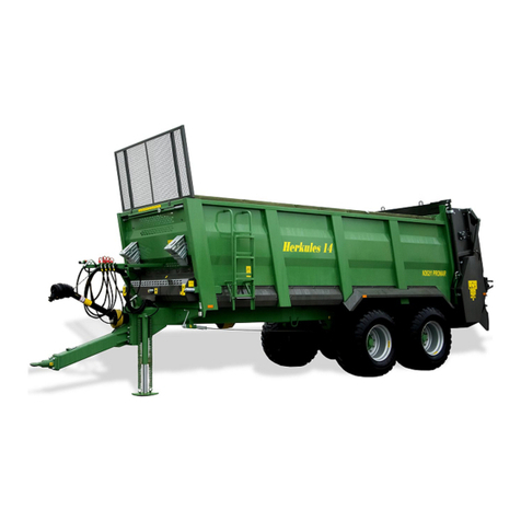
PRONAR N262/2 User manual

PRONAR SP. Z O.O.
17-210 NAREW, UL. MICKIEWICZA 101A, WOJ. PODLASKIE
TEL.: +48 085 681 63 29 +48 085 681 64 29
+48 085 681 63 81 +48 085 681 63 82
FAX: +48 085 681 63 83 +48 085 682 71 10
www.pronar.pl
ISSUE 2B
08-2020
EDITION NO. 624.01.UM.2B.EN
EN
OPERATOR`S MANUAL
MANURE SPREADER
PRONAR N262/2
TRANSLATION OF THE ORIGINAL COPY OF THE MANUAL


INTRODUCTION

Introduction
2PRONAR N262/2
INTRODUCTION
The information contained in the publi-
cation is current as at the date of publi-
cation. As a result of improvement, some
sizes and illustrations contained in this
publication may not correspond to the
actual state of the machine delivered to
the user. The manufacturer reserves the
right to introduce constructional changes
in the manufactured machines to facilitate
operation and improve the quality of their
work, without making any current changes
to this publication.
The operating instruction is the basic
equipment of the machine. Before using
the machine, the user must read the
contents of this manual and observe all
recommendations contained therein. This
will guarantee safe and trouble-free oper-
ation of the machine. The machine was
constructed in accordance with applicable
standards, documents and current legal
regulations.
If the information contained in the oper-
ating instructions does not turn out to be
comprehensible, please contact the sales
ofce where the machine was purchased
or directly to the Manufacturer.
After purchasing the machine, we rec-
ommend to enter the machine serial
number in the elds below.
U.10.1.EN
Machine serial number
This manual contains important safety and operating instructions for the machine. The manual
should be kept near the machine so that it is available for authorized persons.
Keep this manual for future reference. If the manual is lost or damaged, contact the seller or
the manufacturer for a duplicate.
The manual instruction is intended for the end user. For this reason, some required
maintenance is listed in the inspection tables but the procedure is not described in this
publication. To perform them, call the manufacturer's authorized service center.

3PRONAR N262/2
Introduction
SYMBOLS USED IN THE MANUAL
DANGER
Information, descriptions of hazards and
precautions as well as instructions and
orders related to the safety of use in the
content of the manual are marked with
a frame with the word DANGER. Failure to
comply with these recommendations may
endanger the health or life of persons op-
erating the machine or bystanders.
CAUTION
Particularly important information and rec-
ommendations, the observance of which
is absolutely necessary, are highlighted in
the text with a frame saand word CAUTION.
Failure to comply with these recommen-
dations creates the risk of damage to the
machine due to improper handling, ad-
justment or use.
ADVICE
Additional instructions contained in the
manual describe useful information on op-
erating the machine and are marked with
a frame with the word ADVICE.
U.02.1.EN
DANGER
CAUTION
ADVICE

Introduction
4PRONAR N262/2
DESIGNATION OF DIRECTIONS IN THE MANUAL
Left side – the left hand side of the ob-
server facing the machine in the forward
direction.
Right side – the right hand side of the ob-
server facing the machine in the forward
direction.
Turn right – turn the mechanism clockwise
(operator facing the mechanism).
Turn left – turn the mechanism counter-
clockwise(operatorfacingthemechanism).
U.03.1.EN
BA
C
D
Figure 1.1 Determining directions on the machine
(A) - front (B) rear (C) right side (D) left side

5PRONAR N262/2
Introduction
CHECKING THE MACHINE AFTER DELIVERY
The manufacturer ensures that the ma-
chine is fully functional, has been checked
in accordance with control procedures and
is approved for use. However, this does
not release the user from the obligation to
check the vehicle after delivery and before
rst use. The machine is delivered to the
user completely assembled.
THE SCOPE OF CONTROL ACTIVITIES
• Check that the completion of the de-
livered machine matches your order.
• Check if the PTO shaft for connecting
to the tractor complies with the oper-
ating parameters of your tractor.
• Check the condition of the paint
coating.
• Visually inspect machine compo-
nents for mechanical damage re-
sulting, e.g., from incorrect machine
transportation.
• Check the technical condition of tel-
escopic articulated shafts and their
covers.
• Check gears for leaks.
• Check the condition of the tires on
the road wheels and the air pressure
in the tires.
• Check the technical condition of the
exible hydraulic and pneumatic
hoses.
• Make sure there are no hydraulic oil
leaks.
• Check the manure lighting lamps.
U.31.1.EN
ADVICE
The delivery of the machine includes a detailed in-
spection and check of the operation of the machine,
as well as instructing the buyer on the basic prin-
ciples of use. The first start -up takes place in the
presence of the Seller.

Introduction
6PRONAR N262/2
START-UP
• Familiarize yourself with the content
of this manual and the operation
manual of the PTO shaft attached to
the machine and follow the recom-
mendations contained therein.
• Before connecting the manure
spreader, check the suitability of the
tractor for this purpose. The manure
spreader may only be aggregated
with agricultural tractors that meet all
the requirements specied in the table
Agricultural tractor requirements.
• Before connecting, make sure that
the hydraulic oils used in both ma-
chines can be mixed.
• Adjust the height of the drawbar to
the hitch on your tractor.
• Perform a daily review according to
the guidelines in the schedule.
• Check the correct tightening of
screw connections (in particular the
suspension, drawbar eye and road
wheels).
• Make sure that the articulated tel-
escopic shaft (WPT) can be con-
nected to the tractor (the shaft should
be adapted to the specic tractor in
terms of length, type, strength, etc.).
• Check the length of the telescopic
articulated shaft in the lightest and
toughest operating conditions.
• Check if there is sufcient coverage
of the pipes for the widest angle.
• Check if it can still be pushed down at
the smallest angle (turn).
• Check the compatibility of PTO shaft
turns
• Check the compliance of the tractor
PTO speed setting with the required
rotational drive speed of the manure
spreader.
• Connect the machine to the tractor.
• By activating individual lights, check
the correct operation of the electrical
system.
• Perform a test drive. While driving,
check the braking effect of the manure
spreader.
• Perform a test run - chapter (4.5).
Start and check the operation of:
feeding mechanism, gate valve
control, rear cover control, hydraulic
support control (if present), adapter
drive.
• Stop the tractor and turn off the
engine, immobilize the tractor and
CAUTION
The first start-up involves checking the machine in
the presence of the Seller. The Seller is obliged to
carry out training in the safe and proper operation of
the machine.

7PRONAR N262/2
Introduction
the manure spreader with the parking
brake.
U.33.1.EN

Introduction
8PRONAR N262/2


Table of contents
INTRODUCTION
Introduction _________________________________________________________ 2
Symbols used in the manual ____________________________________________ 3
Designation of directions in the manual____________________________________ 4
Checking the machine after delivery ______________________________________ 5
Start-up ___________________________________________________________ 6
GENERAL
1.1 Identication ________________________________________________ 1.2
1.2 Intended use ________________________________________________ 1.4
1.3 Equipment __________________________________________________ 1.7
1.4 Terms of warranty ____________________________________________ 1.8
1.5 Transport ___________________________________________________ 1.9
1.6 Threat to the environment ______________________________________ 1.11
1.7 Withdrawal from use __________________________________________ 1.12
SAFETY OF USE
2.1 Basic safety rules_____________________________________________ 2.2
2.2 Safety when the machine aggregating ____________________________ 2.4
2.3 Safety rules for operating hydraulic and pneumatic systems____________ 2.5
2.4 Safe operation of the PTO shaft _________________________________ 2.6
2.5 Rules of safe technical service __________________________________ 2.8
2.6 Safe driving rules _____________________________________________ 2.11
2.7 Tires _______________________________________________________ 2.13
2.8 Description of residual risk______________________________________ 2.14
2.9 Information and warning stickers _________________________________ 2.15
CONSTRUCTION AND PRINCIPLE OF OPERATION
3.1 Technical characteristics _______________________________________ 3.2
3.2 General construction __________________________________________ 3.3
3.3 Feeding mechanism___________________________________________ 3.5
3.4 Powertrain __________________________________________________ 3.6
3.5 2-roller spreading adapter ______________________________________ 3.8
3.6 Rear aps of the adapter _______________________________________ 3.10
3.7 Hydraulic system of the feeding mechanism ________________________ 3.12
3.8 Hydraulic valve system ________________________________________ 3.14
3.9 Hydraulic system of the broken support____________________________ 3.16
3.10 Hydraulic steering lock system __________________________________ 3.18
3.11 Hydraulic system (control from the spreader) _______________________ 3.20
3.12 Service brake ________________________________________________ 3.21
3.13 Parking brake________________________________________________ 3.26
3.14 Hydraulic lock system _________________________________________ 3.27
3.15 Electrical lighting installation ____________________________________ 3.28
RULES OF USE
4.1 Adjusting the position of the drawbar______________________________ 4.2
4.2 Connecting and coupling of the manure
spreader ___________________________________________________________ 4.4
4.3 Telescopic support service______________________________________ 4.7

4.4 Operation of the broken hydraulic support__________________________ 4.9
4.5 Test run ____________________________________________________ 4.11
4.6 Loading the loading box________________________________________ 4.13
4.7 Disconnecting from the tractor ___________________________________ 4.15
4.8 Load transportation ___________________________________________ 4.16
4.9 Spreading and fertilizing dose adjusting ___________________________ 4.18
4.10 Clogging of the spreading mechanism_____________________________ 4.21
4.11 Use of tires__________________________________________________ 4.22
4.12 Cleaning____________________________________________________ 4.23
4.13 Preparation for the end of the season _____________________________ 4.25
4.14 Preparation for the season______________________________________ 4.26
4.15 Storage ____________________________________________________ 4.27
TECHNICAL INSPECTION SCHEDULE
5.1 General ____________________________________________________ 5.2
5.2 Periodic inspections of the manure spreader________________________ 5.3
5.3 Preparation of the manure spreader for inspection ___________________ 5.6
5.4 Checking the air pressure in the wheels ___________________________ 5.7
5.5 Air tank drainage _____________________________________________ 5.8
5.6 Checking plugs and connection sockets ___________________________ 5.9
5.7 Covers inspection ____________________________________________ 5.10
5.8 Transmission oil lling and top-up ________________________________ 5.11
5.9 Control and regulation of oor conveyor chains tension _______________ 5.13
5.10 Checking and replacing the adapter knives _________________________ 5.14
5.11 Checking the manure spreader before driving off ____________________ 5.16
5.12 Measurement of air pressure, check tires and wheels_________________ 5.17
5.13 Cleaning the air lters _________________________________________ 5.18
5.14 Checking brake lining wear _____________________________________ 5.19
5.15 Checking the clearance of the axle bearings ________________________ 5.20
5.16 Checking of mechanical brakes _________________________________ 5.22
5.17 Cleaning the drainage valve ____________________________________ 5.23
5.18 Checking of parking brake cable tension ___________________________ 5.24
5.19 Hydraulic system Checking _____________________________________ 5.26
5.20 Control of pneumatic braking system______________________________ 5.27
5.21 Suspension control ___________________________________________ 5.28
5.22 Lubrication __________________________________________________ 5.30
5.23 Screw connections inspection ___________________________________ 5.36
5.24 Transmission oil change _______________________________________ 5.38
5.25 Replacement of hydraulic hoses _________________________________ 5.40
TECHNICAL SUPPORT
6.1 Wheel assembly and disassembly________________________________ 6.2
6.2 Parking brake cable replacement ________________________________ 6.3
6.3 Adjusting the clearance of the axle bearings ________________________ 6.5
6.4 Brake adjustment _____________________________________________ 6.6
6.5 Electrical system service and warning elements _____________________ 6.11
6.6 Adapter disassembly and assembly ______________________________ 6.12
6.7 Assembly and disassembly of silo extensions _______________________ 6.14
6.8 Consumables ________________________________________________ 6.15
6.9 Faults and how to remove them__________________________________ 6.17
TIRE ASSEMBLY

GENERAL
CHAPTER 1

Chapter 1 General
1.2 PRONAR N262/2
1.1 IDENTIFICATION
The manure spreader has been marked
with a name plate (1) and a serial number
- gure (1.1). The meaning of individual
elds placed on the plates is presented in
the table (1.1).
When purchasing the machine, check that
the serial numbers on the machine match
the number entered in the WARRANTY
CARD, in the sales documents and in the
USER MANUAL.
The serial number of the driving bearings
and its type are stamped on the nameplate
(2) - gure (1.2) attached to the driving
axle beam. After purchasing the machine,
we recommend that you enter the indi-
vidual serial numbers of the axes in the
elds below.
Figure 1.1 Spreader identication
(1) nameplate
(2) serial number
624-E.01-1
SZB2622XXL1X00001
PRONAR
1
A
B
C
D
E
F
G
H
I
J
K
2
624-E.02-1
1 2
17-210 Narew POLSKA
PRONAR
Sp. z o.o.
ID1-
ECE
ID3-
ID4-
ID2-
TUV25 TUV40
UTAC25 UTAC40
A1D
25 40 60
3013P
BLH07213B BLH07313B
2019
PA90X3013P09A667xxxxx
11800 11000 10000
12900 12000 11000
10600 10000 9000
7848
120252-19-TAC
3
Figure 1.2 Driving axle identication
(1) driving axle
(2) nameplate
(3) axle serial number

Chapter 1
1.3PRONAR N262/2
General
E.3.10.624.01.1.EN
ADVICE
Contact with the service department requires provid-
ing the factory number of the manure spreader and
often the number of axle, so we recommend that you
write these numbers in the manual and have access
to them.
Table 1.1. Nameplate markings
Item Meaning
A General information and function
B Symbol / type
C Year of machine production
D Seventeen-digit serial number (VIN)
ECerticate approval number
F The machine's karb weight
G Permissible gross weight
H Capacity
I Permissible load on the coupling device
J Permissible front axle load
K Permissible rear axle load

Chapter 1 General
1.4 PRONAR N262/2
1.2 INTENDED USE
Pronar manure spreader is designed for
even spreading of all types of manure, peat
and compost. Using the manure spreader
in a manner other than described above
is not allowed. Intended use also includes
all activities related to the correct and safe
operation and maintenance. The manure
spreader is not intended for the transport
of people and animals.
The manure spreader may only be aggre-
gated with agricultural tractors that meet
all the requirements specied in the table
Agricultural tractor requirements.
The braking system as well as the lighting
and signaling system meet the require-
ments arising from trafc regulations. The
set speed must not be exceeded (the
speed limit is based on trafc laws and de-
pends on the country in which the manure
spreader is operated). The manure
spreader speed must not, however, be
greater than the maximum design speed
40 km/h.
Intended use also includes all activities re-
lated to the correct and safe operation and
maintenance of the machine. Therefore,
the user is obliged to:
• Read the content of theUSER
MANUAL and with WARRANTY
CARD and to the guidelines contained
in these documents,
• understand the principle of machine
operation and the safe and proper
operation,
• work in compliance with established
maintenance and adjustment plans,
• work in compliance with general
safety regulations,
• accident prevention,
• comply with road trafc regulations
and transport regulations in force in
the country in which the machine is
used,
• get acquainted with the contents
of the farm tractor and PTO shaft
manual (WPT) and comply with their
recommendations,
• couple the machine only with such
an agricultural tractor that meets all
the requirements set by the spreader
Manufacturer.
The machine may only be used by persons
who:
• Become familiar with the contents of
publications and documents attached
to the machine and the contents of
DANGER
The machine may not be used for purposes other
than those for which it is intended.

Chapter 1
1.5PRONAR N262/2
General
Table 1.2. Agricultural tractor requirements
Content Unit Requirements
Pneumatic braking system
Pneumatic control socket - Yellow according to PN-ISO 1728
Pneumatic supply socket - Red accordance with PN ISO 1728
Nominal pressure of the pneumatic system bar/ kPa 6.5 / 650
Hydraulic brake connection - in accordance with ISO - 7241-1
Nominal pressure of the pneumatic system bar / MPa 160 / 16
Electrical system
Supply voltage V 12
Supply socket - 7 poles in accordance with ISO1724
The hydraulic system
Number of connections for controlling the
oor conveyor (control from the tractor)
Number of connections for controlling the
lock (control from the tractor)
Number of connections for controlling the
rear aps (control from the tractor)
Number of connections for controlling the
hydraulic support (option)
Number of connections to control the dis-
tributor from the manure spreader (option)
-
-
-
-
1 pair
1 pair
1 pair
1 pair
1 pair
Hydraulic oil - L HL 32 Lotos (1)
Nominal pressure of the system bar / MPa 160 / 16
Coupling device
Pin or ball coupling mm 45 or 50 or K80
Minimum capacity (vertical load) on the
coupling device kg 4 000
Other requirements
Min. tractor power KM/ kW 150 / 110.3
PTO rotational speed rpm 1 000
PTO rotation direction Clockwise (looking at the shaft
head)
(1)
– a different oil may be used, provided it can be mixed with oil in the manure spreader.
Detailed information can be found in the product information card.

Chapter 1 General
1.6 PRONAR N262/2
manual agricultural tractor,
• have been trained in trailer operation
and work safety,
• have the required authorization to
drive and are familiar with the trafc
rules and transport regulations.
The manure spreader may not be used for
purposes other than those for which it is
intended, in particular:
• for transporting people, animals, haz-
ardous materials, aggressive loads
as a result of chemical reactions to
manure spreader elements,
• for transporting and spreading toxic
and ammable materials,
• for spreading liquids, sand or brous
substances,
• for transporting machines and de-
vices whose location of the centre of
gravity negatively affects the stability
of the manure spreader,
• for the transport of building materials,
individual objects or any materials
and substances that do not fall within
the scope of intended use,
• overloading the manure spreader
over the maximum load capacity.
E.3.10.624.02.1.EN
Table of contents
Other PRONAR Spreader manuals
Popular Spreader manuals by other brands

Jofemar
Jofemar BT-11 user manual

Kverneland
Kverneland Exacta-CL-GEOSPREAD user manual

New Leader
New Leader AGCO NL4258G4 Operator's manual

LEHNER
LEHNER SuperVario Operating instructions with spare parts list

SnowEx
SnowEx SP-9500X Owner's and operator's manual

EINHELL
EINHELL 3415411 Original operating instructions

Westward
Westward 10F633 Operating instructions and parts manual

Land Pride
Land Pride PS25120 Operator's manual

SPYKER
SPYKER S80-12010 Operator's manual

Echo
Echo RB-80 Operator's manual

Fisher
Fisher QUICK-CASTER 300W Owner's manual and installation instructions

SnowEx
SnowEx Super Maxx SP-9300XH Owner's manual and installation instructions