Venus DR-4020 Operation instructions

DR-4020 DUAL BAND QRP DIGITAL RADIO
Assemble Instructions
The kit consists of two PCBs, one for the control board and the other for the mainboard. All
components on the control board have been installed and tested. There are two integrated
circuits and four crystals on the main board are patch components, and the rest are common
leaded components. It is easy to install. There are only four inductors to be adjusted in the
kit. It can be worked as long as there is no error in the component soldering,and no components
issues.

Components List
QTY
ITEM
Part number
Marks
PCB
1
IC
SA602
Polar
2
IC1、IC2
Resistor
33
2
R5、R6
Resistor
220
1
R8
Resistor
470
1
R7
Resistor
1.2K
1
R9
Resistor
2.2K
2
R1、R2
Resistor
10K
3
R4、R10、R11
Resistor
2.2M
1
R3
diode
1N4148
Polar
4
D2、D3、D4、D5
diode
1N5817
Polar
1
D1
IC
NE5532
Polar
1
IC3
Crystal
4.9152M
4
X1、X2、X3、X4
Resistor row
B06-222
1
PR1
Resistor row
B08-223
1
PR2
Relay
EA2-12NU
Polar
4
K1、K2、K3、K4
3.5 jack
PJ-3001S
2
IN、OUT
Ceramic
capacitor
4.7P
3
C7、C32、C35
Monolithic
capacitor
10P
2
C14、C15
Monolithic
capacitor
15P
1
C13
Monolithic
capacitor
27P
3
C2、C19、C37
Monolithic
capacitor
30P
1
C1
Monolithic
capacitor
47P
3
C34、C36、C48
Monolithic
capacitor
68P
3
C6、C31、C33
Monolithic
capacitor
100P(101)
3
C5、C12、C21

Monolithic
capacitor
150P(151)
2
C3、C46
Monolithic
capacitor
220P(221)
1
C49
Monolithic
capacitor
330P(331)
1
C51
Monolithic
capacitor
470P(471)
1
C47
Monolithic
capacitor
1000P(102)
3
C26、C50、C52
Ceramic
capacitor
0.01(103)
5
C22、C24、C39、C40、C45
Monolithic
capacitor
0.1(104)
10
C8、C9、C10、C17、C18、C20
C25、C27、C41、C42

ITEM
Part number
QTY
Marks
Electrolytic
capacitor
10uF
Polar
2
C23、C28
Electrolytic
capacitor
100uF
Polar
3
C29、C30、C43
Inductor
4.7uH
2
L1、L2
Transistor
DTC143ZSA
Polar
7
Q1、Q2、Q3、Q4、Q5、Q6、Q7
Transistor
2N4401
Polar
3
Q8、Q9、Q10
Regulator
78L05
Polar
1
78L05
Regulator
78L06
Polar
1
78L06
AF transformer
600:600
2
T1、T2
Inductor
10uH
1
L7
Power switch
PS-22F02
1
S1
Toroid inductor
T37-2
2
L8、L9
Toroid inductor
8:2
1
T3
Enameled wire
0.4mm
2
Red and Yellow(inductor/tranfo)
Power jack
005/022B
1
(+V12)
40 inductor
7*7
marks 5
2
L3、L4
20 inductor
7*7
marks 2
2
L5、L6
BNC
BNC-KWYE
1
ANT
Transistor
IRF510
Polar
1
Q11
M3*8 screw
1
fix Q11
M3 nut
1
fix Q11
Insulation pad
1
fix Q11
Insulation
grain
1
fix Q11
Power switch
cap
1
Encoder knob
1
Control board
1
Assemble and tested
M3*5 screw
平头
9
Fix enclosure/front panel
Enclosure
1 set
Panels + enclosure
Power cord
1
AF cable
2
The component list has been arranged according to the order of the components, as long as they
are installed in the order of the list. The components with the direction indicated in the list
must be soldered in the direction of the silk screen on the PCB. Do not solder Q11 first!

The kit has three inductors that require the user to wind it first:
The inductor L8 is wound with a yellow enamel wire 10 turns, and the inductor L9 is wound with a red enamel 12
turns, see photo.
The T3 transformer is an 8:2 transformer with a primary red envelope wrapped around 8 turns, a secondary with a
yellow enameled wire wound around 2 turns, and a primary (red wire) welded to the two pads near the front panel
(near C39), secondary (Yellow) soldered to the two pads near the back panel (near 78L05).
L8, L9 and T3 should be soldered with a soldering iron before the PCB is mounted on the PCB and soldered to
ensure reliable soldering.
Install the middle of the mark "5" at the positions of L3 and L4, and the middle of the mark "2" at the positions of
L5 and L6.

After installing the components on the mainboard, mount the rear panel and fix the Q11, solder the Q11, and
subtract the excess pins. The Q11 should be insulated from the panel with insulating pads and insulating particles.
Please refer to the photo below.

Solder the control board and cut off the excess pin section to install the front panel. The photo of the
installed kit is as follows:

Now you can start debugging the kit. Check the installation and
soldering, then turn on the power switch. If the current is
about 50mA, it is normal. If the current is too large or too
small, it indicates that there is a fault. After the subsequent
debugging.
The receiving of the radio does not need to be adjusted.
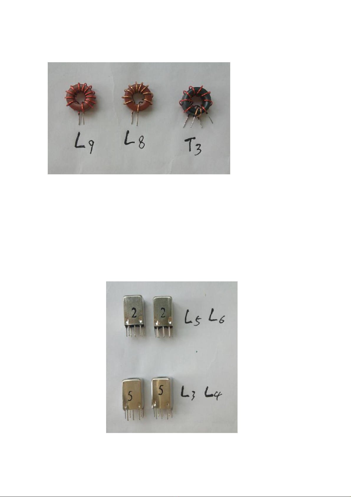
The transmitting only needs to adjust the core of the inductors L3 and L4 to maximize
the transmitting power on 40-meter band, and adjust the core of inductors L5 and L6
to maximize the transmitting power on 20-meter band. .
After that,you may connect the radio to the computer according to the instruction
manual.
Better to connect to a dummy load, if you don’t have a dummy load so may connect to
the resonate antenna.
Use the tuning function in the data communication application software to adjust the
volume to the appropriate position. The power should not be overloaded. As long as
the TX can be triggered, adjust the core of L3 and L4 to maximize the transmit power
on 40-meter band. In the same way, the cores of L5 and L6 are adjusted to maximize
the transmission power on 20-meter band. If there is no power meter, the power can be
judged according to the current of the power supply, and the current can be adjusted
to the maximum. The current meter can not only see the brightness of the transmission
indicator TX is roughly adjusted.
Please refer to the instruction manual for adjustment and operation
of the kit.
Wuxi Venus Information Technology Co., Ltd
Table of contents
Popular Radio manuals by other brands

Eurotops Versand
Eurotops Versand 50740 user manual

Rassbach Communications
Rassbach Communications FreedomLINK installation instructions

Logitech
Logitech 930-000097 - Squeezebox Radio Network Audio... Features guide

Goodmans
Goodmans GCD200 instruction manual

Milwaukee
Milwaukee M18 user manual

Easy wave
Easy wave RCP24 quick start guide