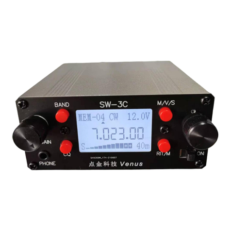
Venus SW-3B User manual

SW-3B
3 band CW QRP transceiver
SW-3B is an ultra-small, ultra-lightweight three-band CW QRPtransceiver that consumes less than 40mA when
receiving.It is ideal for portable use,field day and SOTA.
Specifications:
Dimensions: 104*71*25mm (excluding the protruding part such as knob)
Weight: 180g.
Operating voltage: 8-15VDC.
Operating current:
receiving: about 45mA(backlight on), and less than 40mA(backlight off).
transmitting: about 0.8A (at 12V voltage).
Frequency range: 5-8MHz, 8-11MHz, 11-16MHz (the receiving sensitivity peak is only 40m, 30m, 20m amateur band).
Transmitting: 7.0-7.2MHz, 10.1-10.15MHz, 14.0 -14.35MHz.
Two filters: CW and SSB are automatically switched according to the operating mode.
The CW filter has a bandwidth of about 400 Hz and the SSB is about 2 kHz.
The adjustment range of RIT/XIT
RIT: -9KHz to +9KHz, XIT adjustment range: -30KHz to +30KHz. Output power Approx. 5W (power supply voltage is 12V)
Side tone: 600Hz
Auto keyer: The built-in auto keyer speed is adjustable.
Storage: Each band has 8 storage frequency channel, and the frequency and operating mode can be stored by the user arbitrarily.
Receiving mode: CW, CWR, USB, LSB. It can also be transmitted in the SSB mode of receiving, enabling cross-linking of CW/SSB.
AGC: Simple Audio AGC, S meter shows the relative strength of the signal and is for reference only.

Connections
External power supply:
Any 8-15V DC voltage or battery can be connected through the external power interface. The power interface has a
polarity protection circuit to prevent the power supply from damaging the machine.
Headphones:
Connect a stereo headset to the headphone jack (PHONE) with an impedance of 8-32 ohms.
Antenna:
Any resonant antenna can be directly connected to the antenna interface (ANT) with a BNC connector. For non-
resonant antennas, an antenna tuner should be connected between the antenna interface and the antenna.
Key/Paddle:
Automatically recognizing the electronics key and the straight key. Just connect the straight key to the mono plug or
connect the middle ring of the stereo plug to the ground below as shown below. When the power is turned on, the
circuit will be based on the inserted key. Different automatic detection is performed. When you hear a click (Morse
code letter A), it is an electronics key, and you hear a click (Morse code letter M) as a straight key. (Be sure to insert
the hand button into the socket before turning on the power to enter the hand button function).
3.5mm Stereo plug
paddle dit or straight key
paddle dat or straight key GND Boot screen
paddle GND/straight key GND
Operating
Power Switch and Gain Control:
The power switch is located in the lower left corner of the panel. The RF GAIN and AF
GAIN knobs on the radio panel are the front-end high-frequency gain control and audio
gain control, respectively, clockwise to the maximum gain.
Band Selection:
Two toggle switches on the right side of the panel BAND are band selection switches,
and the two wave switches are linked. The switch positions 1, 2, and 3 correspond to
the 40m, 30m, and 20m bands, respectively. Each band has 8 storage frequency points,
and the frequency and working mode of each frequency point can be set by the user.

M/V/SAV button
Pressing this button will switch between the memory frequency (MEM) and the VFO. The upper left corner of the LCD will display
MEM-** or VFO-** (** is the number of 01-08). When MEM-** is displayed, it is stored in frequency mode. At this time, turning the large
knob can change the storage frequency point, clockwise rotation increases, and counterclockwise rotation decreases. When VFO-** is
displayed, the frequency mode is changed. At this time, turning the large knob can change the operating frequency, the clockwise
rotation frequency increases, and the counterclockwise rotation frequency decreases.
Press the M/V/SAV button for more than 2 seconds to store the current frequency and operating mode to the current memory
location. The Sav-** text will be displayed in the upper left corner of the LCD screen. Each time when turned on, it will enter the
frequency and working mode of the last timeit was stored
RT/MOD button
tap of this button will enter or exit the Receive Fine Tune and Transmit Fine Tune (RIT and XIT) functions.
At this time, the RIT or XIT and the fine adjustment of the fine adjustment are displayed on the upper right of
the LCD screen. Pressing the tuning large knob after entering the fine tuning state will switch between
receiving fine tuning RIT and transmitting fine tuning XIT.
Rotate the large knob to fine tune the receive or transmit frequency. The step frequency of RIT is 10Hz, and the step
frequency of XIT is 100Hz.
Pressing the RT/MOD button for more than 2 seconds will change the working mode. Each press of the button for 2 seconds
will change the working mode in the order of CW, CWR, USB, LSB.
Frequency step change
Tap the large knob step frequency to switch between 10Hz, 100Hz, 1KHz and 100KHz. When the step frequency is changed, there
is a small triangle mark above the corresponding frequency display position of the LCD screen. If you press the large knob while in
the MEM state, it will enter the VFO working state.

Backlight Mode Selection
Press and hold the M/V/SAV button and the RT/MOD button simultaneously to enter the backlight setting state.
Turn the large knob to change the backlight setting. The backlight of the LCD has three settings: ON is the
backlight always on, OFF is the backlight is always off, AUTO is automatic, if you select the automatic, if the
machine is not operated for 10 seconds, the backlight will automatically turn off, and the backlight will
automatically turn on when the machine is operated. Press and hold the M/V/SAV button and the RT/MOD button
simultaneously to exit the backlight setting state.
Transmitting
Allowed transmission frequencies are: 7.0-7.2 MHz, 10.1-10.15 MHz, and 14.0-14.35 MHz. When the signal is
sent within these frequency ranges, the display will show the word TX, and the red LED on the right side of the
panel will flash with the code. When not transmitting in these frequency ranges, it will be invalid. The ERROR will
be displayed on the display. No signal will be sent from the antenna, but the side tone can still be heard. You can
use this feature as a code trainer.
Electronics keyer
1. Automatic Calling:
Short press the CQ button to release it immediately, that is, automatically call CQ CQ de + call sign twice + K. If you want
to cancel the automatic call during the automatic call, press the CQ button for 1 second and release it. The following 2 and 3
operations must be performed in the automatic key state, and invalid when using the key.
2. Speed adjustment:
Press the CQ button and hold it. After about 2 seconds, you will hear dit dit dit (Moores code letter S). At this
time, release the CQ button, and the auto button will be dialed to “point” speed. Slow down to the "scratch" speed.
At the right speed (you will automatically exit after 8 seconds of input and keep the original speed). Short press
the CQ button to release it immediately, hear dit (Moores code E) exit, or wait for about 8 seconds to exit
automatically.
3. Call sign input:
Press the CQ button and hold it. After about 2 seconds, you will hear dit dit dit (Morse code letter S), continue
to hold down the CQ button, and hear it after about 2 seconds (Morse code) The letter I), at this time release the
CQ button, use the automatic button to dial your call sign as usual (unless input will automatically exit after 8
seconds, and keep the original call sign). After the hair is sent, press the CQ button and release it immediately.
When you hear dit (Moores code E), or wait for about 8 seconds to exit automatically. When the speed
adjustment and call sign input status are entered, the display will show the word TX, which is normal.

Adjust:
the adjustable capacitors on the PCB board VC1 and VC2 are used to adjust the receiving sensitivity of the 20-
meter band. The adjustable capacitor VC3 is used to adjust the receiving sensitivity of the 30-meter band. The
adjustable capacitor VC4 is used to adjust the receiving sensitivity of the 40-meter band. Make adjustments if
needed. The RV1 adjustable resistor on the PCB board is the calibration resistor for the supply voltage. This
adjustable potentiometer calibration can be adjusted if there is an error in the voltage display.
If the transmission frequency of the machine is deviated, you can adjust it as follows:
Turn off the power, and press and hold the M/V/SAV button and the RT/MOD button to turn on the power. The display shows
the following:
At this time, use the frequency counter to detect the frequency of the TEST point on the PCB board (near the power socket), turn the
large knob to adjust the frequency to the frequency counter display 10.000.00MHz, then press the M/V/SAV button to exit.
Accessories: Power cord (4.0 x 1.7mm DC jack)
BNC-SO239 adaptor
Wuxi Venus Information Technology Co., Ltd
https://ba4tb.qth.com

2019 - 04
Table of contents
Other Venus Transceiver manuals