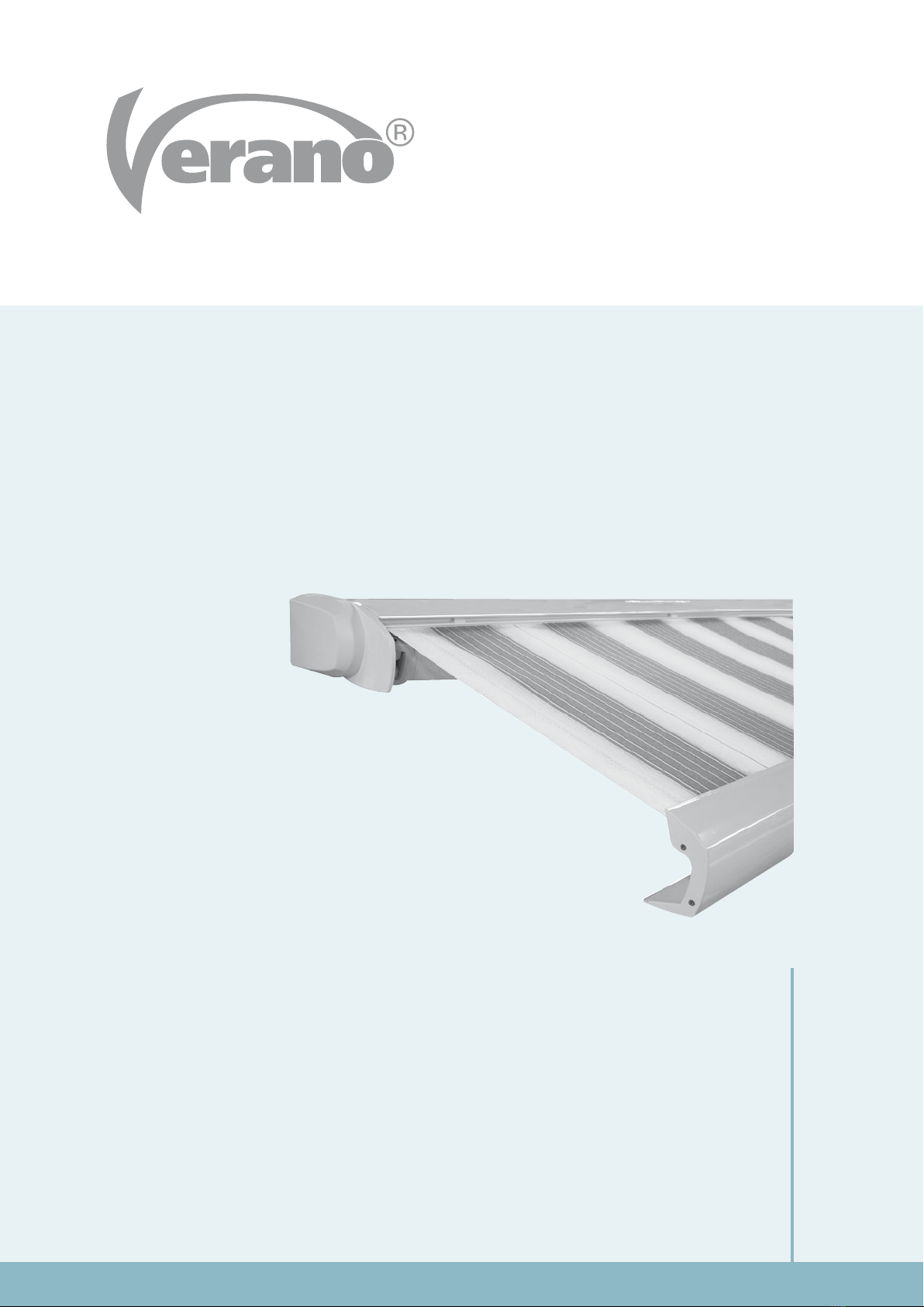
INSTALLATION MANUAL AWNING V285 - RECIFE
1780-190906EN
4
Subject to misprints, errors and technical modifications.
1.1 Marking the holes
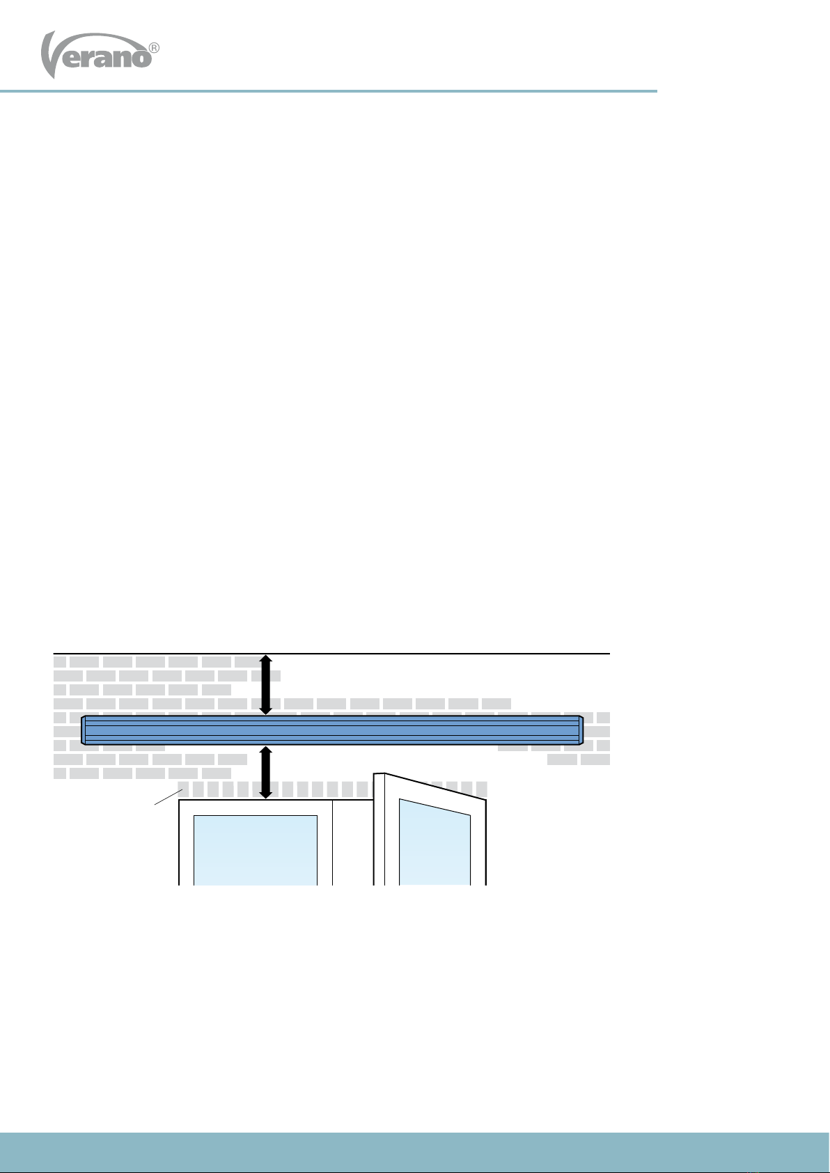
Mark the holes for the wall supports (A) and potential for
the intermediate support (B) on the wall. These holes need
to be aligned level, horizontal and vertical, according to the
sizes X and Y in gure 1.1.
Attention! Size X is the width of the awning without side
covers. Make sure that there are at least two holes in the
middle of a stone. View gure 1.2.
If necessary, use an alignment string.
X = width of the awning without side covers.
Y = height of the window frame plus a minimum of 30 cm.
A = wall support, always use four bolts.
B = center support, with an awning bigger than 450 cm.
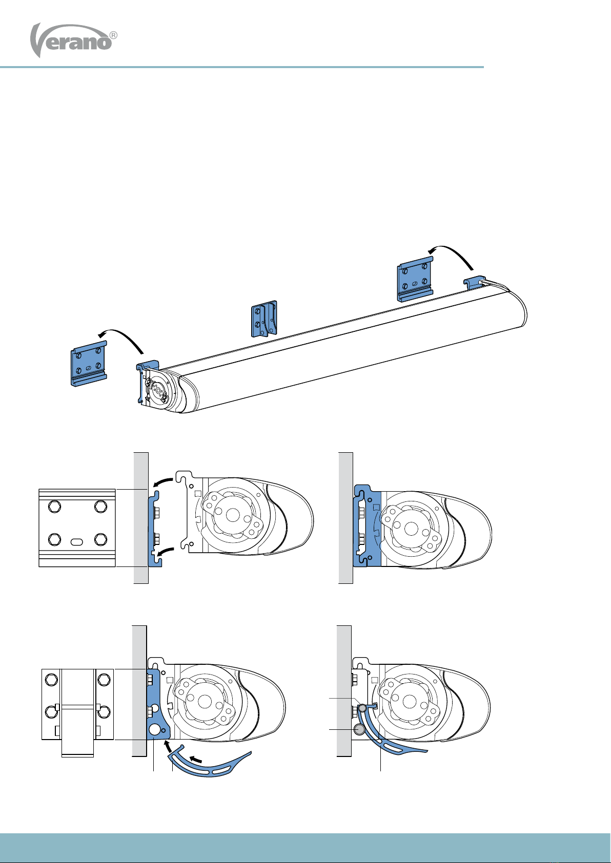
g. 1.1 Placing wall supports
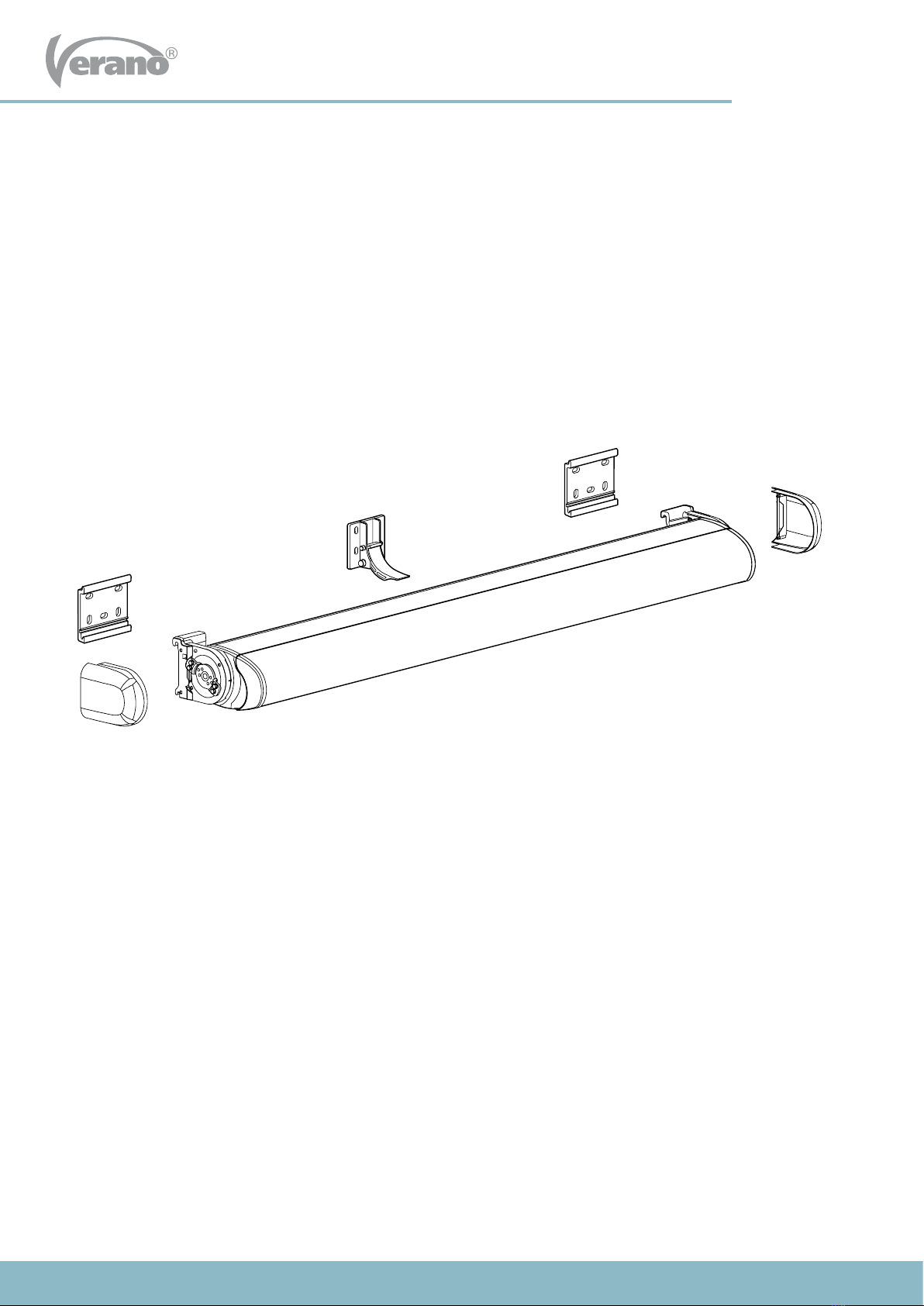
1. Mounting wall supports
1.2 Drilling the holes
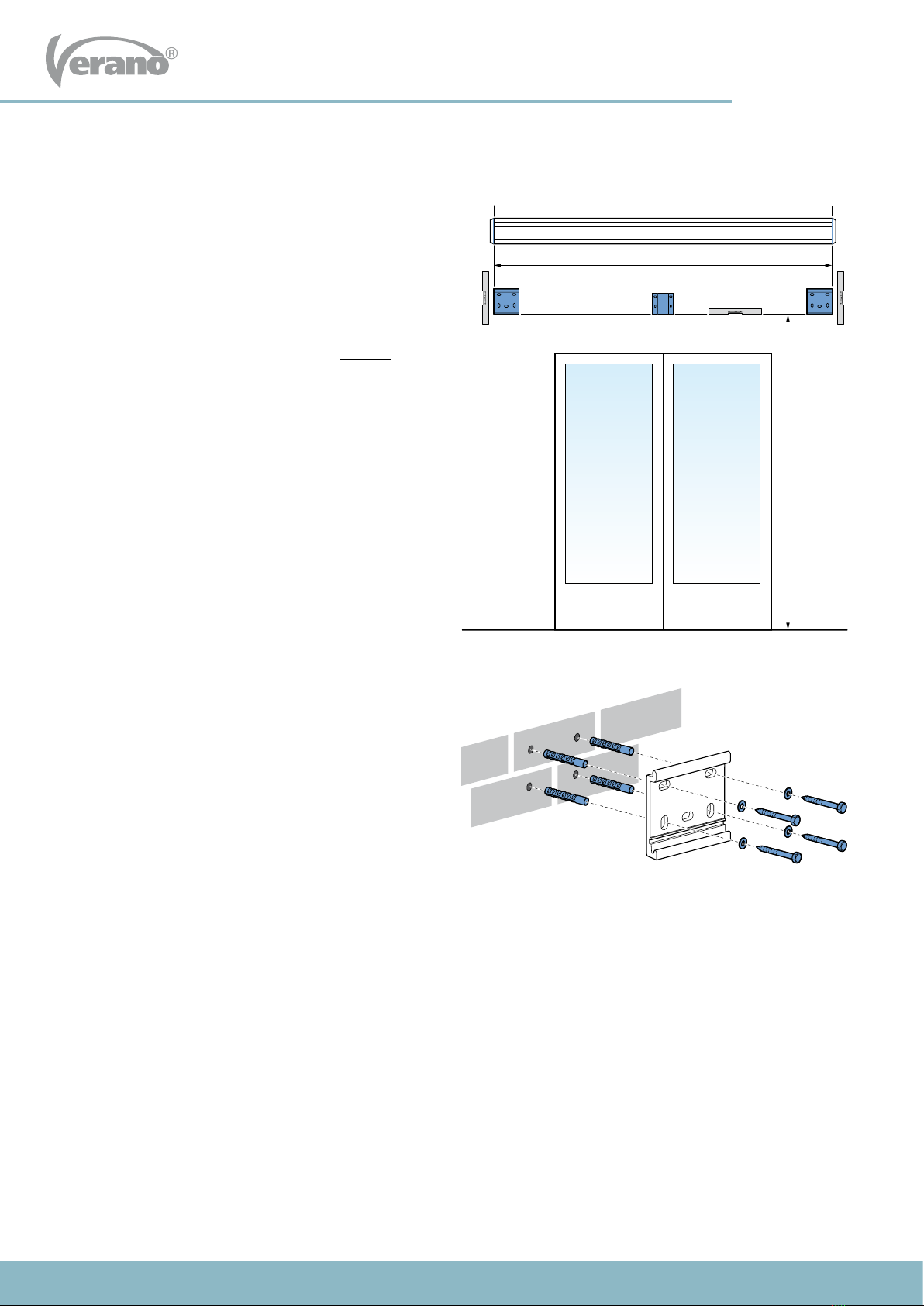
Drill the mounting holes. Our advise is to drill with a 14 mm
masonry drill in case of a wall made of concrete or stone.
Use matching plugs and bolts of high quality. Mount the
wall supports (A) and potential the intermediate support(s)
(B) and tighten the bolts.
View gure 1.2.
Attention! Mount only the mounting plate from the
center support. The adjustable part will be placed
later on.
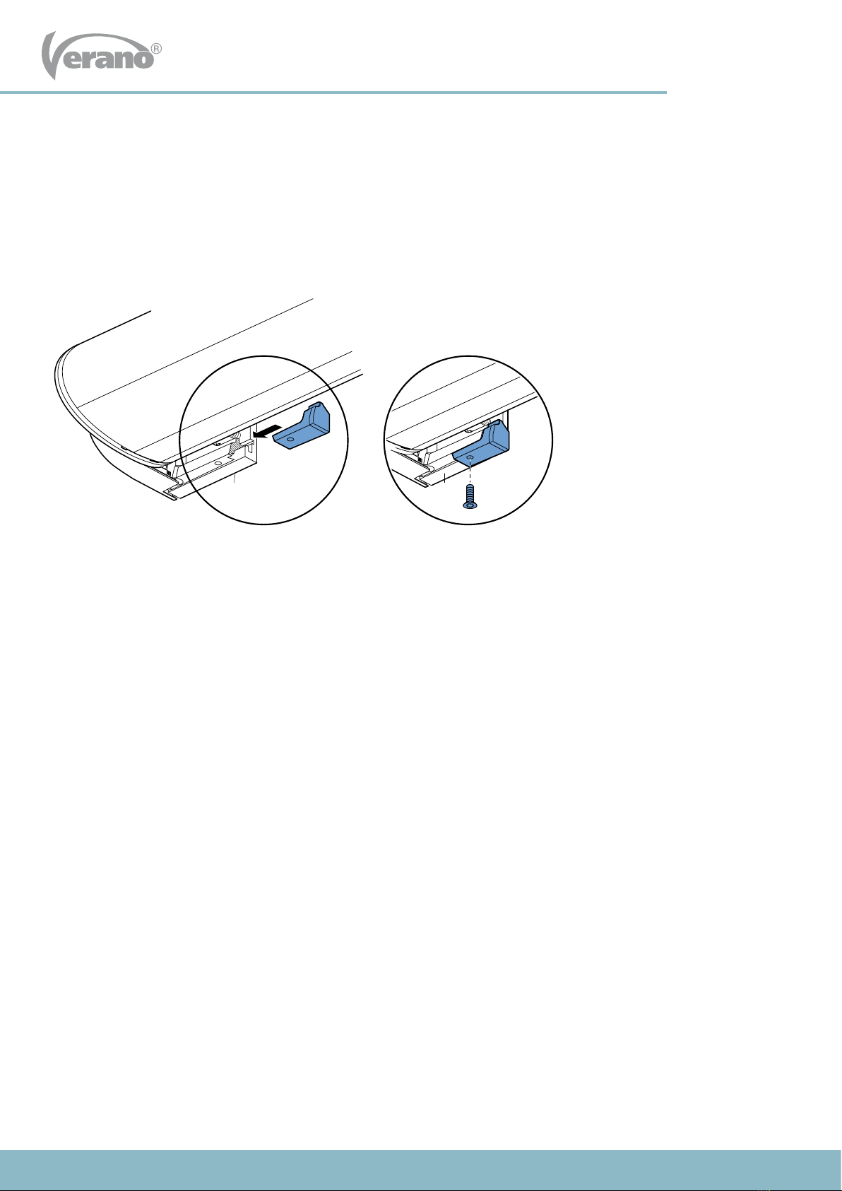
1.3 Drilling the hole for control
If you want to connect your wall control on the inside, measure the place of the control hole carefully. This depends on
your personal preference and situation.
Drill inwards with a 10 millimeter drill. When drilling through the wall, it is advisable to place a shelf against the inner side
of the wall to prevent damages to the wall.
g. 1.2 Mounting the wall supports