e-
VERDERAIR E-PURE ATEX_v1 | 30.10.2023 10
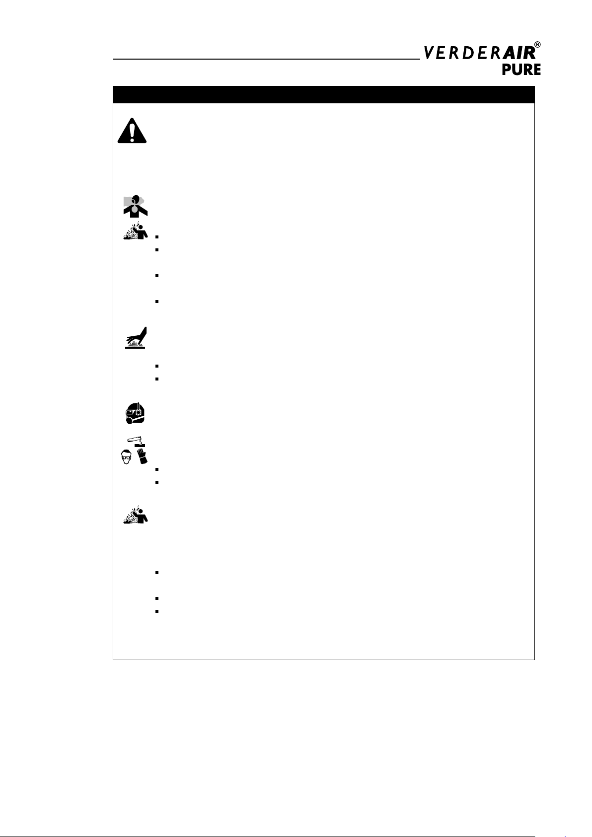
Mounting
To avoid serious injury or death from toxic uid or
fumes:
Never move or lift a pump under pressure. If
dropped, the uid section may rapture. Always
follow the Pressure Relief Procedure on page 12
before moving or lifting the pump.
1. Be sure the mounting surface can support the
weight of the pump, hoses and accessories, as
well as the stress causes during operation.
2. Make sure the surface is at and that the pump
doesn’t wobble.
3. For ease of operation and service, mount the
pump so uid inlet and uid outlet ports are
easy accessible.
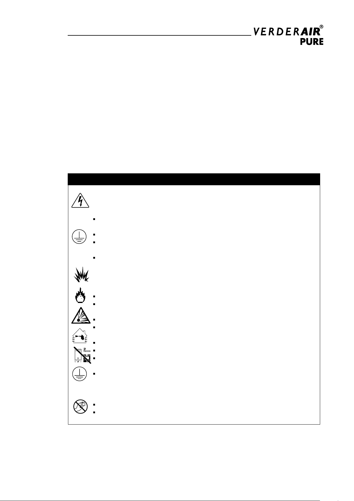
Grounding
The equipment must be grounded. Grounding
reduces the risk of static sparking and electric
shock. Electric or static sparking can cause
fumes to ignite or explode. Improper grounding
can cause electric shock. Grounding provides an
escape wire for the electric current.
Check your system electrical continuity after the
initial installation. Set up a regular schedule for
checking continuity to be sure proper grounding in
maintained.
Never use a non-conductive pump with non-
conductive ammable uids. Follow your local re
codes. When pumping ammable uids, always
ground the entire uid system as described.
Fluid suction line
1. A shut of valve should be installed just before
the pump to isolate the pump from the system
for maintenance and installation.
2. Always use a exible connection to avoid
vibrations being brought into the piping system.
The hoses should be grounded.
3. For sealing use an appropriate gasket
compatible with the connections of pump.
4. Use a suction line which can stand vacuum.
By the pumping action, vacuum will be created
at the suction side of the pump.
Fluid outlet line
1. A shut of valve should be installed just after
the pump isolate the pump from the system
for maintenance and installation. A drain valve
should be installed to relief the pressure of the
pump.
2. Always use a exible connection to avoid
vibrations being bought into the piping system.
The houses should be grounded.
3. For sealing use an appropriate gasket
compatible with the connections of the pomp.
Fluid inlet and outlet ports
1. VA-EP series of pump are having the suction
and discharge connections integrated in the
center block. The pumps are delivered as
standard with inlet port on the same side as
drive terminal box.
2. By changing the ports you need rotating vertical
the center housing 180°.
Installation remarks
1. VA-EP pumps must be installed load free
to avoid possible damage of pumps and/or
installation. There must be no external force on
any connection part of the pump. Be especially
careful not to have the pump support part of the
weight of the hose and the piping.
2. Use a sturdy hose that will not collapse under
the strong suction of the pump. The hose must
be of more than sufcient pressure rating.
3. Use a hose of a diameter the same as or larger
than the pump's ports. If the diameter of a hose
is smaller, it will affect the pump's performance
or cause its malfunction.
4. VA-EP pumps will be delivered with blind plugs
to prevent dust or other materials to enter the
pump. Those plugs have to be removed before
installing the pump.
5. As UV – radiation can damage Polyethylene. This
must taken in account by installing VA-EP pumps
made out of PE (pump code VA-EPxx EP)
6. VA-EP pumps are dry self-priming. So they don’t
need to be lled before rst use. The gures of
the possible suction heights can be found in the
technical information (see page 25).