VERIS INDUSTRIES, INC. E50H2A User manual

ZL0117-0H Page 1 of 28 ©2017 Veris Industries USA 800.354.8556 or +1.503.598.4564 / suppor[email protected] 0517
Alta Labs, Enercept, Enspector, Hawkeye, Trustat, Aerospond, Veris, and the Veris ‘V’ logo are trademarks or registered trademarks of Veris Industries, L.L.C. in the USA and/or other countries.
Other companies’ trademarks are hereby acknowledged to belong to their respective owners.
For use ina Pollution Degree 2or betterenvironment only.A Pollution Degree2 environment must
controlconductive pollutionand thepossibility ofcondensation orhigh humidity.Considerthe
enclosure,the correct useof ventilation, thermalproperties ofthe equipment,and therelationship with
theenvironment. Installationcategory: CAT IIorCATIII. Providea disconnect device todisconnect the
meter from the supply source. Place this device inclose proximity totheequipment andwithineasy
reach of theoperator, andmarkit as thedisconnecting device.The disconnecting device shallmeetthe
relevant requirements ofIEC 60947-1and IEC60947-3andshallbesuitable for the application. Inthe US
andCanada,disconnecting fuseholderscanbeused. Provide overcurrentprotection anddisconecting
device for supply conductors with approved current limiting devices suitable for protecting thewiring.
If the equipmentis used inamanner not specifiedby the manufacturer,the protectionprovided bythe
devicemaybeimpaired.
HAZARD OF ELECTRIC SHOCK, EXPLOSION, OR ARC FLASH
• Follow safe electrical work practices. See NFPA 70E in the USA, or applicable local codes.
• This equipment must only be installed and serviced by qualified electrical personnel.
• Read, understand and follow the instructions before installing this product.
• Turn off all power supplying equipment before working on or inside the equipment.
• Product may use multiple voltage/power sources. Disconnect ALL sources before
servicing.
• Use a properly rated voltage sensing device to confirm that power is off.
DO NOT DEPEND ON THIS PRODUCT FOR VOLTAGE INDICATION.
• Current transformer secondaries must be shorted or connected to a burden at all times.
• Products rated only for basic insulation must be installed on insulated conductors.
• Replace all doors, covers and protective devices before powering the equipment.
Failure to follow these instructions will result in death or serious injury.
A qualied person is one who has skills and knowledge related to the construction and
operation of this electrical equipment and installations, and has received safety
training to recognize and avoid the hazards involved. NEC Article 100
If this product is used in a manner not specied by the manufacturer, the protection
provided by the product may be impaired. No responsibility is assumed by the
manufacturer for any consequences arising out of the use of this material.
DANGER
NOTICE
• This product is not intended for life or safety applications.
• Do not install this product in hazardous or classied locations.
• The installer is responsible for conformance to all applicable codes.
• Mount this product inside a suitable re and electrical enclosure.
FCC PART 15 INFORMATION
NOTE: This equipment has been tested by the manufacturer and found to
comply with the limits for a class B digital device, pursuant to part 15 of
the FCC Rules. These limits are designed to provide reasonable protection
against harmful interference when the equipment is operated in a
residential environment. This equipment generates, uses, and can radiate
radio frequency energy and, if not installed and used in accordance with
the instruction manual, may cause harmful interference to radio
communications. This device complies with part 15 of the FCC Rules.
Operation is subject to the following two conditions:
(1) This device may not cause harmful interference, and
(2) this device must accept any interference received, including
interference that may cause undesired operation.
Modifications to this product without the express authorization of the
manufacturer nullify this statement.
WARNING
LOSS OF CONTROL
∙ Assure that the system will reach a safe state during and after a control path failure.
∙ Separate or redundant control paths must be provided for critical control functions.
∙ Test the eect of transmission delays or failures of communication links.1
∙ Each implementation of equipment using communication links must be individually
and thoroughly tested for proper operation before placing it in service.
Failure to follow these instructions may cause injury, death or equipment damage.
1For additional information about anticipated transmission delays or failures of the link, refer to
NEMA ICS 1.1 (latest edition). Safety Guidelines for the Application, Installation, and Maintenance
of Solid-State Control or its equivalent in your specic country, language, and/or location.
Control system design must consider the potential failure modes of control paths and, for
certain critical control functions, provide a means to acheive a safe state during and after a
path failure. Examples of critical control functions are emergency stop and over-travel stop.
TM
Installation Guide
Power Monitoring
Product Identication
Model BACnet MS/TP
Protocol Output
Alarm
Output
Full Data
Set
Data
Logging
Pulse
Input
E50H2A • • • •
E50H5A • • •
•
(2 pulses)
Product Overview
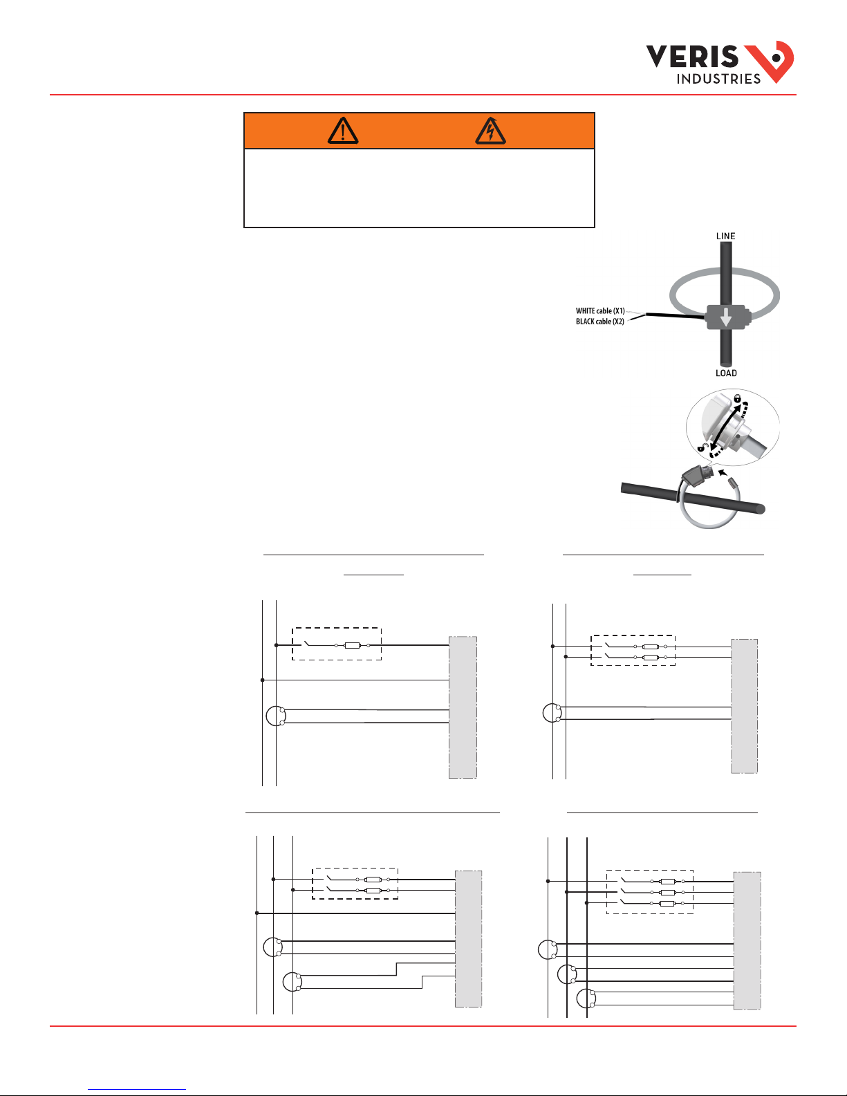
The E50H2A and E50H5A DIN rail power meters provide a solution for measuring energy data with a single device.
Inputs include control power, CT, and 3-phase voltage. Both models support BACnet MS/TP protocol. The E50H2A
has one pulse contact input and a phase loss alarm output. The E50H5A has data logging capability and two pulse
contact inputs. The LCD screen on the faceplate allows instant output viewing. These meters include built-in CT
integrators and CT power supplies. The E50H2A and E50H5A work only with Veris E683 series rope style CTs.
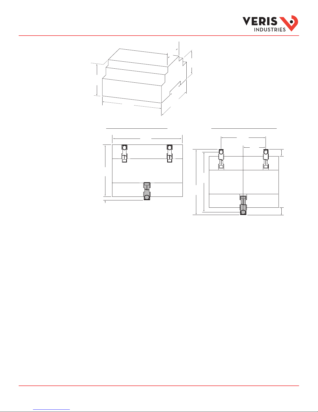
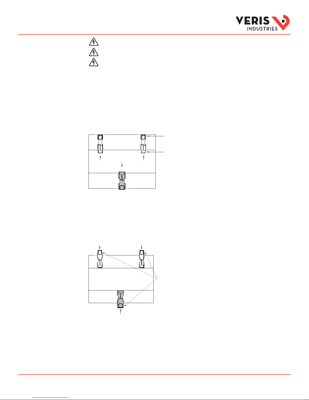
The meter is housed in a plastic enclosure suitable for installation on T35 DIN rail according to EN50022. It can be
mounted with any orientation over the entire ambient temperature range, either on a DIN rail or in a panel. The
meters are not sensitive to CT orientation, reducing installation errors.
E50H2A, E50H5A
Compact Power and Energy Meters
With BACnet MS/TP Support
For Use Only With E683 Series Rope CTs
Specications
MEASUREMENT ACCURACY
Real Power and Energy IEC 62053-22 Class 0.5S, ANSI C12.20 0.5%
Reactive Power and Energy IEC 62053-23 Class 2, 2%
Current 0.4% (+0.015% per °C deviation from 25 °C) from 5% to 100% of range;
0.8% (+0.015% per °C deviation from 25 °C) from 1% to 5% of range
Voltage 0.4% (+0.015% per °C deviation from 25 °C) from 90 VL- N to 600 VacL- L
Sample Rate 2520 samples per second
Data Update Rate 1 sec
Type of Measurement True RMS up to the 21st harmonic 60 Hz; One to three phase AC system
INPUT VOLTAGE CHARACTERISTICS
Measured AC Voltage Minimum 90 VL- N (156 VL- L) for stated accuracy;
UL Maximum: 600 VL- L (347 VL-N);
CE Maximum: 300 VL-N
Metering Over-Range +20%
Impedance 2.5 MΩL- N /5 MΩL-L
Frequency Range 45 to 65 Hz
INPUT CURRENT CHARACTERISTICS
CT Scaling 50 to 5000 A measured range*; 400 to 5000 A breaker size
Measurement Input Range E683 Series rope style CTs only (CTs must be rated for connection to Class 1
voltage inputs)
E683 Series CT
(sold separately)
*
*The CE mark indicates RoHS2 compliance. Please refer to the CE Declaration of
Conformity for additional details.

ZL0117-0H Page 2 of 28 ©2017 Veris Industries USA 800.354.8556 or +1.503.598.4564 / support@veris.com 0517
Alta Labs, Enercept, Enspector, Hawkeye, Trustat, Aerospond, Veris, and the Veris ‘V’ logo are trademarks or registered trademarks of Veris Industries, L.L.C. in the USA and/or other countries.
Other companies’ trademarks are hereby acknowledged to belong to their respective owners.
TM
Installation Guide
Power Monitoring
CONTROL POWER
AC 5 VA max.; 90 V min.
UL Maximum: 600 VL- L (347VL-N ); CE Maximum: 300 VL- N
DC** 3W max.; UL and CE: 125 to 300 Vdc
Ride Through Time 100 msec at 120 Vac
INPUT
Pulse Solid-state or mechanical contacts (current less than 1 mA);
E50H2A: 1 pulse input; E50H5A: 2 pulse inputs
Minimum Pulse Width 20 msec
OUTPUT
Alarm Contacts (E50H2A only) N.C., static output; (30 Vac/dc, 100 mA max.@ 25 °C, derate 0.56 mA per °C
above 25 °C)
RS-485 Port 2-wire, 9600 to 115.2 kbaud, BACnet MS/TP
MECHANICAL CHARACTERISTICS
Weight 0.62 lb (0.28 kg)
IP Degree of Protection
(IEC 60529)
IP40 front display; IP20 meter
Display Characteristics Back-lit blue LCD
Terminal Block Screw Torque 0.37 to 0.44 ft-lb (0.5 to 0.6 N·m)
Terminal Block Wire Size 24 to 14 AWG (0.13 to 2.08 mm2)
Rail T35 (35mm) DIN Rail per EN 50022
OPERATING CONDITIONS
Operating Temperature Range -30 to 70 °C (22 to 158 °F)
Storage Temperature Range -40 to 85 °C (-40 to 185 °F)
Humidity Range <95% RH non-condensing
Altitude of Operation 3000 m
Mounting Location Not suitable for wet locations. Indoor use only.
COMPLIANCE INFORMATION
US and Canada CAT III, Pollution Degree 2;
for distribution systems up to 347 VL- N /600VacL- L
Europe (CE) IEC 61010-1
CAT III, Pollution Degree 2;
for distribution systems up to 300 VL- N
Dielectric Withstand Per UL 508, IEC 61010-1
Conducted and Radiated Emissions FCC part 15 Class B, EN 55011/EN 61000 Class B (residential and light
industrial)
Conducted and Radiated Immunity EN 61000 Class A (heavy industrial)
US and Canada (cULus) UL 508 (open type device)/CSA 22.2 No. 14-05
*Not recommended for environments where high harmonic content is present.
** External DC current limiting is required, see fuse recommendations.
Specications
(cont.)

ZL0117-0H Page 3 of 28 ©2017 Veris Industries USA 800.354.8556 or +1.503.598.4564 / support@veris.com 0517
Alta Labs, Enercept, Enspector, Hawkeye, Trustat, Aerospond, Veris, and the Veris ‘V’ logo are trademarks or registered trademarks of Veris Industries, L.L.C. in the USA and/or other countries.
Other companies’ trademarks are hereby acknowledged to belong to their respective owners.
TM
Installation Guide
Power Monitoring
Table of Contents Dimensions 4
Data Outputs 4
Product Diagram 5
Display Screen Diagram 5
Installation 6
Supported System Types 7
Wiring Symbols 7
Wiring 8
Control Power Diagrams 9
Quick Setup Instructions 10
Pulse Contact Input 11
User Interface Menu Abbreviations Dened 11
User Interface for Data Conguration 12
Alert/Reset Information 13
User Interface for Setup 14
RS-485 Communications 16
BACnet Default Settings 17
BACnet Programming Information 18
Troubleshooting 28
China RoHS Compliance Information (EFUP Table) 28

ZL0117-0H Page 4 of 28 ©2017 Veris Industries USA 800.354.8556 or +1.503.598.4564 / support@veris.com 0517
Alta Labs, Enercept, Enspector, Hawkeye, Trustat, Aerospond, Veris, and the Veris ‘V’ logo are trademarks or registered trademarks of Veris Industries, L.L.C. in the USA and/or other countries.
Other companies’ trademarks are hereby acknowledged to belong to their respective owners.
TM
Installation Guide
Power Monitoring
Dimensions
4.2”
(107mm)
3.6”
(91mm)
1.5”
(39mm)
2.3”
(59mm)
1.9”
(48mm)
1.8”
(45mm)
3.6“
(91 mm)
4.2“
(107 mm)
0.2“
(4 mm)
3.9“
(99 mm)
2.4“
(61 mm)
++
+
4.3“
(109 mm)
1.2“
(31 mm) 0.3“
(8 mm)
0.4“
(10 mm)
Bottom View (DIN Mount Option) Bottom View (Screw Mount Option)
Full Data Set (FDS):
Power (kW)
Energy (kWh)
Congurable for CT & PT ratios, system type, and passwords
Diagnostic alerts
Current: 3-phase average
Volts: 3-phase average
Current: by phase
Volts: by phase Line-Line and Line-Neutral
Power: Real, Reactive, and Apparent 3-phase total and per phase
Power Factor: 3-phase average and per phase
Frequency
Power Demand: Most Recent and Peak
Demand Conguration: Fixed, Rolling Block, and External Sync
Real Time Clock: uses BACnet Time Synchronization services
Data Logging (E50H5A only; includes all FDS outputs, plus):
3 BACnet Log_Events: each buer holds 5760 time-stamped 32-bit entries
(User congures which 3 data points are stored in these buers)
User congurable logging interval
(When congured for a 15 minute interval, each buer holds 60 days of data)
Continuous and Single Shot logging modes: user selectable
Data Outputs

ZL0117-0H Page 5 of 28 ©2017 Veris Industries USA 800.354.8556 or +1.503.598.4564 / support@veris.com 0517
Alta Labs, Enercept, Enspector, Hawkeye, Trustat, Aerospond, Veris, and the Veris ‘V’ logo are trademarks or registered trademarks of Veris Industries, L.L.C. in the USA and/or other countries.
Other companies’ trademarks are hereby acknowledged to belong to their respective owners.
TM
Installation Guide
Power Monitoring
Display Screen
Diagram
Tx
Rx
ERR
♥
Screen Name or Units
Diagnostic Alert:
indicates that one or
more of the alarm
bits (Binary_Objects
1-15) are active.
Logo
Numeric Data
Alive Indicator
RS-485 Equipped Units Only:
Transmit Data
Receive Data
Receive Data Error
LCD Screen: Buttons:
+
–
(Up)
Select
(Right)
Next
(Down)
Select
(Left)
Back
Alarm Energy
Two 5-character rows
of display text.
Top row alphanumeric;
Bottom row numeric only
The red Alarm LED lights
when any of the 3 phase
voltages drop below the
selected threshold.
The green Energy LED lights
when the pulse 1 input
contacts are active or closed.
CONTROL POWER
0.1A 50/60 Hz
A B C N 1 2
Pulse Inputs
1 2 + - S
RS-485
VA
VB
VC
Neutral
Earth
Control
Power
UL: 90V L-N - 600V L-L CE: 90V L- N - 300V L-N
VOLTAGE INPUTS
CAT III 50/60 Hz
+
–
Pulse Input 1
Pulse Input 2
BACnet
Shield
(X2) A(X1) (X2) B(X1) (X2) C(X1)
IA
IB
IC
X2 X1 X2 X1 X2 X1
CT Inputs E683 Series Only
kWh
1234.5
Alarm Energy
kWh
1234.5
Two 5-character rows
of display text.
Top row alphanumeric;
Bottom row numeric only
The red Alarm LED lights
when any of the 3 phase
voltages drop below the
selected threshold.
The green Energy LED is not
used on the E5xH2A.
CONTROL POWER
0.1A 50/60 Hz
A B C N 1 2
+ - S
RS-485
VA
VB
VC
Neutral
Earth
Control
Power
UL: 90V L-N - 600V L-L CE: 90V L- N - 300V L-N
VOLTAGE INPUTS
CAT III 50/60 Hz
+
–
Phase Loss
Alarm Output
Pulse Input
BACnet
Shield
(X2) A(X1) (X2) B(X1) (X2) C(X1)
IA
IB
IC
X2 X1 X2 X1 X2 X1
CT Inputs E683 Series Only
E50H2A
E50H5A
Product Diagrams

ZL0117-0H Page 6 of 28 ©2017 Veris Industries USA 800.354.8556 or +1.503.598.4564 / support@veris.com 0517
Alta Labs, Enercept, Enspector, Hawkeye, Trustat, Aerospond, Veris, and the Veris ‘V’ logo are trademarks or registered trademarks of Veris Industries, L.L.C. in the USA and/or other countries.
Other companies’ trademarks are hereby acknowledged to belong to their respective owners.
TM
Installation Guide
Power Monitoring
Installation Disconnect power prior to installation.
Reinstall any covers that are displaced during the installation before powering the unit.
Mount the meter in an appropriate electrical enclosure near equipment to be monitored.
Do not install on the load side of a Variable Frequency Drive (VFD), aka Variable Speed Drive (VSD)
or Adjustable Frequency Drive (AFD).
The meter can be mounted in two ways: on standard 35 mm DIN rail or screw-mounted to the interior surface of the enclosure.
A. DIN Rail Mounting
1. Attach the mounting clips to the underside of the housing by sliding them into the slots from the inside. The stopping pegs
must face the housing, and the outside edge of the clip must be ush with the outside edge of the housing.
2. Snap the clips onto the DIN rail. See the diagram of the underside of the housing (below).
Clip flush with
outside edge
Snap onto
DIN rail
Insert clips from inside
3. To reduce horizontal shifting across the DIN rail, use two Veris AV02 end stop clips.
B. Screw Mounting
1. Attach the mounting clips to the underside of the housing by sliding them into the slots from the outside. The stopping pegs
must face the housing, and the screw hole must be exposed on the outside of the housing.
2. Use three #8 screws (not supplied) to mount the meter to the inside of the enclosure. See the diagram of the underside of the
housing (below).
Screw holes
exposed for
mounting
Insert clips from outside

ZL0117-0H Page 7 of 28 ©2017 Veris Industries USA 800.354.8556 or +1.503.598.4564 / support@veris.com 0517
Alta Labs, Enercept, Enspector, Hawkeye, Trustat, Aerospond, Veris, and the Veris ‘V’ logo are trademarks or registered trademarks of Veris Industries, L.L.C. in the USA and/or other countries.
Other companies’ trademarks are hereby acknowledged to belong to their respective owners.
TM
Installation Guide
Power Monitoring
Supported System
Types
To avoid distortion, use parallel wires for control power and voltage inputs.
The following symbols are used in the wiring diagrams on the following pages.
Symbol Description
Voltage Disconnect Switch
Fuse (installer is responsible for ensuring compliance with local requirements. No
fuses are included with the meter.)
Earth ground
X2
X1 Current Transducer
Potential Transformer
Protection containing a voltage disconnect switch with a fuse or disconnect circuit
breaker. The protection device must be rated for the available short-circuit current at
the connection point.
• This product is designed only for use with E683 Series current transducers (CTs).
• DO NOT USE CURRENT OUTPUT (e.g. 5A) CTs ON THIS PRODUCT.
Failure to follow these instructions can result in equipment damage.
NOTICE
RISK OF EQUIPMENT DAMAGE
Wiring Symbols
The E50HxA power meters have a number of dierent possible system wiring congurations (see Wiring section). To congure the
meter, set the System Type via the User Interface or by writing the Present_Value of AV2 with the System Type value in the table
below. The System Type tells the meter which of its current and voltage inputs are valid, which are to be ignored, and if neutral
is connected. Setting the correct System Type prevents unwanted energy accumulation on unused inputs, selects the formula
to calculate the Theoretical Maximum System Power, and determines which phase loss algorithm is to be used. The phase loss
algorithm is congured as a percent of the Line-to-Line System Voltage (except when in System Type 10) and also calculates the
expected Line to Neutral voltages for system types that have Neutral (12 & 40).
Values that are not valid in a particular System Type display as “----” on the User Interface or as QNAN in the BACnet objects.
CTs Voltage Connections System Type Phase Loss Measurements Wiring
Diagram
Number
of wires
Qty ID Qty ID Type BACnet object
AV2
User Interface:
SETUP>S SYS
VLL VLN Balance Diagram
number
Single-Phase Wiring
2 1 A 2 A, N L-N 10 1L + 1n AN 1
2 1 A 2 A, B L-L 11 2L AB 2
3 2 A, B 3 A, B, N L-L with N 12 2L + 1n AB AN, BN AN-BN 3
Three-Phase Wiring
3 3 A, B, C 3 A, B, C Delta 31 3L AB, BC, CA AB-BC-CA 4
4 3 A, B, C 4 A, B, C, N Grounded
Wye
40 3L + 1n AB, BC, CA AN, BN, CN AN-BN-CN &
AB-BC-CA
5, 6

ZL0117-0H Page 8 of 28 ©2017 Veris Industries USA 800.354.8556 or +1.503.598.4564 / support@veris.com 0517
Alta Labs, Enercept, Enspector, Hawkeye, Trustat, Aerospond, Veris, and the Veris ‘V’ logo are trademarks or registered trademarks of Veris Industries, L.L.C. in the USA and/or other countries.
Other companies’ trademarks are hereby acknowledged to belong to their respective owners.
TM
Installation Guide
Power Monitoring
RISK OF ELECTRIC SHOCK OR PERMANENT EQUIPMENT DAMAGE
CT terminals are referenced to the meter’s neutral and may be at elevated voltages:
· Do not contact meter terminals while the unit is connected
· Do not connect or short other circuits to the CT terminals
Failure to follow these instructions may cause injury, death or equipment damage.
WARNING
Wiring
N L1
X2
X1 White
Black
A
B
C
N
X1
X2
X1
X2
X1
X2
A
B
C
Diagram 1: 1-Phase Line-to-Neutral 2- Wire
System 1 CT
Diagram 2: 1-Phase Line-to-Line 2-Wire
System 1 CT
L1 L2
X2
X1
X2
X1
A
B
C
N
A
B
C
N
White
Black
White
Black
X1
X2
X1
X2
X1
X2
L1 L2
X2
X1
A
B
C
N
A
B
C
White
Black X1
X2
X1
X2
X1
X2
Diagram 3: 1-Phase Direct Voltage Connection 2 CT
L1 L2 L3
X2
X1
A
B
C
N
A
B
C
X2
X1
X2
X1
White
Black
White
Black
White
Black
X1
X2
X1
X2
X1
X2
Diagram 4: 3-Phase 3-Wire 3 CT no PT
Use System Type 11 (2L)
Use System Type 12 (2L + 1n) Use System Type 31 (3L)
Use System Type 10 (1L + 1n)
1. Turn o all power supplying this device and the equipment in which it is
installed before working on the device or equipment.
2. Always use a proerly rated voltage sensing device to conrm that all power
is o.
3. Connect the CT output leads to the meter inputs. The white wire is the X1
lead. The E683x CT has an arrow indicating the source side.
4. Release the clasp on one side of the CT and open it on the hinge.
5. Fit the Rogowski coil around the conductor, bringing the coil ends
together.
6. Lock the coil by turning the ring clockwise as shown in the diagram
at right.
7. Reconnect power to the panel.

ZL0117-0H Page 9 of 28 ©2017 Veris Industries USA 800.354.8556 or +1.503.598.4564 / support@veris.com 0517
Alta Labs, Enercept, Enspector, Hawkeye, Trustat, Aerospond, Veris, and the Veris ‘V’ logo are trademarks or registered trademarks of Veris Industries, L.L.C. in the USA and/or other countries.
Other companies’ trademarks are hereby acknowledged to belong to their respective owners.
TM
Installation Guide
Power Monitoring
Control Power
Direct Connect Control Power (DC Control Power)
L1N L2 L3 1 2G
L1N L2 L3
1 2G
L1
1 2G
L2 L3
Direct Connect Control Power (Line to Neutral)
Line to Neutral from 90 VAC to 347 VAC (UL) or 300 VAC (CE)
1 2G
Control Power Transformer (CPT) Connection
Direct Connect Control Power (Line to Line)
Line to Line from 90 VAC to 600 VAC (UL). In UL installations the
lines may be oating (such as a delta). If any lines are tied to an
earth (such as a corner grounded delta), see the Line to Neutral
installation limits. In CE compliant installations, the lines must
be neutral (earth) referenced at less than 300 VACL-N
The Control Power Transformer may be wired L-N or L-L. Output to
meet meter input requirements
DC Control Power from 125 VDC to 300 VDC
(UL and CE max.)
Fuse Recommendations
Keep the fuses close to the power source (obey local and national code requirements).
For selecting fuses and circuit breakers, use the following criteria:
• Select current interrupt capacity based on the installation category and fault current capability.
• Select over-current protection with a time delay.
• Select a voltage rating sucient for the input voltage applied.
• Provide overcurrent protection and disconnecting means to protect the wiring. For AC installations, use Veris AH02,
AH03, AH04, or equivalent. For DC installations, provide external circuit protection. Suggested: 0.5 A, time delay fuses.
• The earth connection (G) is required for electromagnetic compatibility (EMC) and is not a protective earth ground.
L1N L2 L3
X2
X1
A
B
C
N
A
B
C
X2
X1
X2
X1
White
Black
White
Black
White
Black
X1
X2
X1
X2
X1
X2
Diagram 5: 3-Phase 4-Wire Wye Direct Voltage Input
Connection 3 CT
Use System Type 40 (3L + 1n)
White
Black
White
Black
White
Black
L1N L2 L3
X2
X1
A
B
C
N
A
B
C
X2
X1
X2
X1
X1
X2
X1
X2
X1
X2
Diagram 6: 3-Phase 4-Wire Wye Connection 3 CT
3 PT
Use System Type 40 (3L + 1n)
Wiring (cont.)

ZL0117-0H Page 10 of 28 ©2017 Veris Industries USA 800.354.8556 or +1.503.598.4564 / suppor[email protected] 0517
Alta Labs, Enercept, Enspector, Hawkeye, Trustat, Aerospond, Veris, and the Veris ‘V’ logo are trademarks or registered trademarks of Veris Industries, L.L.C. in the USA and/or other countries.
Other companies’ trademarks are hereby acknowledged to belong to their respective owners.
TM
Installation Guide
Power Monitoring
Use this section to enter:
- BACnet communication parameters
- CT (Current Transducer) output voltage
- The service type to be monitored
These instructions assume the meter is set to factory defaults. If it has been previously congured, check all optional values.
A. To Navigate to the Setup screens:
1. Press +
+or
–
repeatedly until SETUP screen appears.
2. Press to get to the PASWD screen.
3. Press to move through the digits. Use the +
+or
–
buttons to enter your password (the default is 00000).
4. Press to move to the rst Setup screen (S BAC)
5. Use +
+or
–
to select the parameter screen you want to set.
6. After you set the parameters you want, use +
+or
–
to select the next Setup screen or to exit the Setup screens (return to
SETUP).
B. To Enter BACnet communication parameters
1. Navigate to the S BAC (set BACnet) Setup screen (see section A above).
2. Press to go to the MAC screen and through the address digits. Use +
+or
–
to select the BACnet MAC address (default is 001).
3. Press to accept the value and go to the KBAUD screen. Use +
+or
–
to select the baud rate (default is 76.8K).
4. Press to go to the ID1 screen and through the upper four digits of the Device Instance. Use +
+or
–
to select the ID digits.
The setup screen splits the Device ID into two parts, the most signicant four digits (ID1) and the least signicant three digits
(ID2). The E50HxA supports BACnet Device ID values from 1 to 4,193,999. Units are shipped with a factory default setting that is
pseudo-randomly generated in the range from 1,000,000 to 3,097,151.
5. Press to accept the value and go to the ID2 screen and through the lower three digits of the Device Instance. Use +
+or
–
to
select the ID digits.
6. Press to accept the value and go back to the S BAC screen.
C. To Enter the CT (Current Transducer) output voltage and input current ranges:
1. Press to go to the CT SZ screen and through the digits. Use +
+or
–
to select the CT size in amps (default is 100).
2. Press to accept the value and go back to the S CT screen.
D. To Enter the service type to be monitored:
1. Navigate to the S SYS (Set System) Setup screen (see section A above).
2. Press to go to the SYSTM screen. Use +
+or
–
to select the conguration (see wiring diagrams - default is 3LN-1N).
3. Press to go back to the S SYS screen.
For full setup instructions, see the conguration instructions on the following pages.
Quick Setup
Instructions

ZL0117-0H Page 11 of 28 ©2017 Veris Industries USA 800.354.8556 or +1.503.598.4564 / support@veris.com 0517
Alta Labs, Enercept, Enspector, Hawkeye, Trustat, Aerospond, Veris, and the Veris ‘V’ logo are trademarks or registered trademarks of Veris Industries, L.L.C. in the USA and/or other countries.
Other companies’ trademarks are hereby acknowledged to belong to their respective owners.
TM
Installation Guide
Power Monitoring
Pulse Contact Input The E50H5A has two inputs with pulse accumulators for solid state or mechanical contacts in other sensors, such as water or gas
ow meters. These inputs are isolated from the measured circuits and referenced to the communication signal ground. Use with
contacts that do not require current to remove oxidation.
SComm
Output
+
~10 kΩ
Comm
Ground
4-10 VDC
nominal
Pulse Input
Contacts
Equivalent
Circuit
The E50H2A has one input with pulse accumulator as described above, and one phase loss alarm output terminal.
SComm
Output
+
~10 kΩ
Comm
Ground
4-10 VDC
nominal
Phase Loss
Alarm Output
Pulse Input
Equivalent
Circuit
Main Menu
IEC IEEE Description
D D Demand
MAX M Maximum Demand
P W Present Real Power
QVAR Present Reactive Power
SVA Present Apparent Power
A A Amps
UAB, UBC, UAC VAB, VBC, VAC Voltage Line to Line
V VLN Voltage Line to Neutral
PF PF Power Factor
U VLL Voltage Line to Line
HZ HZ Frequency
KSh KVAh Accumulated Apparent
Energy
KQh KVARh Accumulated Reactive
Energy
KPh KWh Accumulated Real Energy
PLOSS PLOSS Phase Loss
LOWPF LOWPF Low Power Factor Error
Main Menu
IEC IEEE Description
F ERR F ERR Frequency Error
I OVR I OVR Over Current
V OVR V OVR Over Voltage
PULSE PULSE kWh Pulse Output Overrun
(conguration error)
_PHASE _PHASE Summary Data for 1, 2, or 3
active phases
ALERT ALERT Diagnostic Alert Status
INFO INFO Unit Information
MODEL MODEL Model Number
OS OS Operating System
RS RS Reset System
SN SN Serial Number
RESET RESET Reset Data
PASWD PASWD Enter Reset or Setup
Password
ENERG ENERG Reset Energy Accumulators
DEMND DEMND Reset Demand Maximums
User Interface (UI)
Menu Abbreviations
Dened
The user can set the display mode to either IEC or IEEE notation in the SETUP menu.

ZL0117-0H Page 12 of 28 ©2017 Veris Industries USA 800.354.8556 or +1.503.598.4564 / support@veris.com 0517
Alta Labs, Enercept, Enspector, Hawkeye, Trustat, Aerospond, Veris, and the Veris ‘V’ logo are trademarks or registered trademarks of Veris Industries, L.L.C. in the USA and/or other countries.
Other companies’ trademarks are hereby acknowledged to belong to their respective owners.
TM
Installation Guide
Power Monitoring
User Interface for
Data Conguration
_PHAS
APHAS
BPHAS
CPHAS
3 A 3 VLL 3 VLN 3 KW
A A A VABA KW
1, 2, o
r 3 Phase
Summary D
ata
Phase A:
All Systems
Phase B:
2 & 3 Phase
Systems Only
Phase C:
3 Phase
Systems Only
A VLN
Volts Line-Line (U)
(Average of Active
Phases)
Amps (A)
(Average of
Active Phases)
Volts Line-Neutral (V)
(Average of Active
Phases)
Total Real
Power (P)
Power Factor
(Average of
Active Phases)
3 KVA
Total Apparent
Power (S)
B A B VBCB KWB VLN
C A C VACC KWC VLN
A KVA
B KVA
C KVA
A PF
3 PF
B PF
C PF
3KVAR
Total Reactive
Power (Q)
AKVAR
BKVAR
CKVAR
KVARhKVAh
Accumulated
Reactive Energy
(Qh)
Accumulated
Apparent Energy
(Sh)
DEMND D KW
Present
Real Power
Demand (P)
M KW MKVARM KVA
Maximum
Apparent Power
Demand (S)
Maximum
Reactive Power
Demand (Q)
Maximum
Real Power
Demand (P)
DKVAR
Present
Reactive Power
Demand (Q)
D KVA
Present
Apparent Power
Demand (S)
DEMND
Demand
>>> Scroll When Idle >>>
To:
SETUP
APHAS
BPHAS
CPHAS
A KWh
3 KWh
B KWh
C KWh
_PHAS
HZ
Frequency
Accumulated
Real Energy
ENRGY
To:
ALERT
Energy
Accumulators
and Co
unters
ENRGY
PULS1
Input Pulse Counter
PULS2
Pulse Counter 2
(not used on E50H2)
KWh
Accumulated
Real Energy
(Ph)
The units for all Power and Energy screens change to preserve resolution as the accumulated totals increase. For ex-
ample, energy starts out as Wh, then switches to kWh, MWh, and eventually GWh as the accumulated value increases.

ZL0117-0H Page 13 of 28 ©2017 Veris Industries USA 800.354.8556 or +1.503.598.4564 / support@veris.com 0517
Alta Labs, Enercept, Enspector, Hawkeye, Trustat, Aerospond, Veris, and the Veris ‘V’ logo are trademarks or registered trademarks of Veris Industries, L.L.C. in the USA and/or other countries.
Other companies’ trademarks are hereby acknowledged to belong to their respective owners.
TM
Installation Guide
Power Monitoring
Alert/Reset
Information
SETUP
ALERT
RESET
Back
Display “nOnE” if no alerts
To Setup
Setup
Meter
Reset
Data
Phase Loss
A B C
Low Power Factor
A B C
Frequency Out
of Range
A
Current
Out of Range
Voltage
Out of Range
A B C
Not used on
E5xHx
A B C
INFO MODEL OS SNRS
Serial
Number
Reset
System
Operating
System
ALERT
INFO
PLOSS
--------
A b C
LOWPF
--------
A b C
F ERR
--------
A
I OVR
--------
A b C
V OVR
--------
A b C
PASWD
--------
00000
PASWD
--------
00000
Model
Number
PULSE
--------
n0nE
ENERG
--------
rES
ResetEnergy
Accumulators to 0
Unit
Information
Alert Status
(check if
Wrench on
LCD)
RESET
Enter Reset
Password
Enter Setup
Password
To: ENRGY
To: DEMND
COUNT
--------
rES
Reset Pulse
Counters to 0
DEMND
--------
rES
Reset Demand
Maximums to Present
PASWD – Enter the Reset Password
(configured in the setup menu).
ENERG – Reset all Energy
Accumulators (Wh, VARh, VAh) to 0.
Press “+” or “-“ to Reset.
DEMND – Reset all Maximum
Demand (W, VAR, VA) to the present
Demand. Hit “+” or “-“ to Reset.
COUNT – Reset the pulse counters.
Press “+” or “-“ to Reset.

ZL0117-0H Page 14 of 28 ©2017 Veris Industries USA 800.354.8556 or +1.503.598.4564 / support@veris.com 0517
Alta Labs, Enercept, Enspector, Hawkeye, Trustat, Aerospond, Veris, and the Veris ‘V’ logo are trademarks or registered trademarks of Veris Industries, L.L.C. in the USA and/or other countries.
Other companies’ trademarks are hereby acknowledged to belong to their respective owners.
TM
Installation Guide
Power Monitoring
Next
From:
SETUP > PASWD
Set Current Transducer:
CT SZ - CT Size: in Amps. Maximum is 5000 Amps.
Set System Configuration:
SYSTM: + or –to step through the following System Type options:
System Reg 130 CTs Description
3L-1n 40 3 Wye Three Phase: A, B, & C with Neutral (Default).
3L 31 3 Delta Three Phase: A, B & C; no Neutral
2L-1n 12 2 Single Split Phase: A & B with Neutral
2L 11 1 Single Phase: A & B; no Neutral
1L-1n 10 1 Single Phase: A to Neutral
System
Type
Current
Transformer
S SYS
Next
S CT
CT SZ
--------
100
SYSTM
--------
3L-1n
3L
2L-1n
2L
1L+1n
Back To SETUP
Back
Back
To Setup p. 2 “SPLOS”
Next
S PT
Set Potential Transfomer Ratio:
RATIO – Potential transformer step down is RATIO:1. Default is 1:1
(No PT installed). See Install for wiring diagrams. This value must be
set before the System Voltage (if used).
Potential
Transformer
RATIO
--------
001.00
Back
S V
Back
Sytem
Voltage Next
Set System Voltage:
V LL – The nominal Line to Line Voltage for the system. This is used
by the meter to calculate the theoretical maximum system power, and
as the reference voltage for setting the Phase Loss threshold.
Maximum is 32000 Volts. For system type 1+N (10), this is a Line to
Neutral Voltage, indicated by “V LN”. Note: the meter will reject settings
that are not within the meter’s operating range when divided by the PT
ratio.
V LL
--------
00600
S PWR
Back
Sytem
Voltage
MX KW
--------
103.92
Next
System Power:
MX KW – The theoretical Maximum System Power is calculated by the
meter from the System Voltage, CT size, and System Type. Power
Factor is assumed to be unity. The value of System Power is used to
determine which combinations of pulse weight and duration are valid
and will keep up with the maximum power the meter will see. This value
is read only.
Note: Bold is the Default.
Next
MAC
--------
001
KBAUD
--------
115.2
76.8
38.4
19.2
9.6
Set Communications Parameters:
ADDR – BACnet MS/TP MAC Address: 0 – 127.
+ increments the selected (blinking) digit.
– selects the digit to the left.
BAUD - Baud Rate: 9600 – 115200 Baud
BACnet ID: These two screens set the 7 digit
BACnet device ID. Screen ID1 is the most
significant 4 digits and ID2 the least significant
three digits. This is in the range of 0 - 4,194,302.
Back S BAC
To:SPASS
ID1
--------
0000
ID2
--------
000
UI for Setup

ZL0117-0H Page 15 of 28 ©2017 Veris Industries USA 800.354.8556 or +1.503.598.4564 / support@veris.com 0517
Alta Labs, Enercept, Enspector, Hawkeye, Trustat, Aerospond, Veris, and the Veris ‘V’ logo are trademarks or registered trademarks of Veris Industries, L.L.C. in the USA and/or other countries.
Other companies’ trademarks are hereby acknowledged to belong to their respective owners.
TM
Installation Guide
Power Monitoring
UI for Setup (cont.)
Next
Set Passwords:
SETUP - The Password to enter the SETUP menu.
RESET - The Password to enter the RESET menu.
RESET
--------
00000
SPASS
Setup
Passwords
SETUP
--------
00000
Back
Next
SDMND
INTRV
--------
6
5
4
3
2
1
Demand
SEC
--------
00900
Back
Set Demand Interval:
INTRV - The number of Sub-Intervals (1 to 6) in a
Demand Interval.Default is 1 (block demand).
SEC - Sub-Interval length in seconds. Default is
900 (15 minutes). Set to 0 for external sync-to-
comms.
Next
S DIS
Display
Units
UNITS
--------
IEEE
IEC
Back
Set Display Units: +/- to switch between:
IEEE – VLL VLN W VAR VA Units.
IEC - U V P Q S Units.
To Setup p. 1 “S PWR”
SPLOS
Back
IMBAL
--------
0.25
Next
VOLTS
--------
0.10
Set Phase Loss:
VOLTS - Phase Loss Voltage: The fraction of the system
voltage below which Phase Loss Alarm is on. For system
types with neutral, the Line to Neutral voltage is also
calculated and tested. If the System Voltage is 600 and the
fraction is set to 0.10, then the Phase Loss threshold will be
60 volts.
IMBAL - Phase Loss Imbalance: The fractional difference
in Line to Line voltages above which Phase Loss Alarm is
on. For system types with neutral, the Line to Neutral
voltages are also tested. For system types 1+N (10) and 2
(11) , imbalance is not tested.
Phase
Loss
To Setup page 1 “S BAC”

ZL0117-0H Page 16 of 28 ©2017 Veris Industries USA 800.354.8556 or +1.503.598.4564 / suppor[email protected] 0517
Alta Labs, Enercept, Enspector, Hawkeye, Trustat, Aerospond, Veris, and the Veris ‘V’ logo are trademarks or registered trademarks of Veris Industries, L.L.C. in the USA and/or other countries.
Other companies’ trademarks are hereby acknowledged to belong to their respective owners.
TM
Installation Guide
Power Monitoring
Daisy-chaining Devices to the Power Meter
The RS-485 slave port allows the power meter to be connected in a daisy chain with up to 63 2-wire devices.
–
+
S
120 Ω terminator on the rst and last
device of the daisy chain
Shield wire
Notes
• The terminal’s voltage and current ratings are compliant with the requirements of the EIA RS-485 communications
standard.
• The RS-485 transceivers are ¼ unit load or less.
• RS-485+ has a 47 kΩ pull up to +5V, and RS-485- has a 47 kΩ pull down to Shield (RS-485 signal ground).
• Wire the RS-485 bus as a daisy chain from device to device, without any stubs. Use 120 Ω termination resistors at each
end of the bus (not included).
• Shield is not internally connected to Earth Ground.
• Connect Shield to Earth Ground somewhere on the RS-485 bus.
For all terminals:
• When tightening terminals, apply the correct torque: 0.37 to 0.44
ft·lb (0.5-0.6 N·m).
• Use 14-24 gauge (2.1-0.2 mm2) wire.
RS-485
Communications
Red
Black
Gray
0.37 to 0.44 ft-lb
(0.5 to 0.6 N-m)
Use 14 to 24 gauge wire

ZL0117-0H Page 17 of 28 ©2017 Veris Industries USA 800.354.8556 or +1.503.598.4564 / support@veris.com 0517
Alta Labs, Enercept, Enspector, Hawkeye, Trustat, Aerospond, Veris, and the Veris ‘V’ logo are trademarks or registered trademarks of Veris Industries, L.L.C. in the USA and/or other countries.
Other companies’ trademarks are hereby acknowledged to belong to their respective owners.
TM
Installation Guide
Power Monitoring
Setting Default Value* BACnet Object
Setup Password 00000 n/a
Reset Password 00000 n/a
System Type 40 (3 + N) Wye AV2
CT Primary Ratio 100A AV3
PT Ratio 1:1 (none) AV5
System Voltage 600 V L-L AV6
Max. Theoretical Power Calculated from AV2, AV3, AV5 & AV6 (with all default settings, this would be
103.92 kW)
AI45
Display Mode 1 (IEEE Units) AV7
Phase Loss Voltage Threshold 10% of System Voltage AV8
Phase Loss Voltage Threshold 25% Phase to Phase Imbalance AV9
Demand: number of
subintervals per interval
1 (block mode) AV10
Demand: sub-interval length 900 sec (15 min)
(AV11 default value is 90000 [1/100 seconds])
AV11
BACnet MAC Address 001 n/a
BACnet MS/TP Baud Rate 76.8 kBaud n/a
BACnet MS/TP Max_Master 127 Device
BACnet Device_ID Pseudo-random value
from 1,000,000 to 3,097,151
Device
BACnet Device Location Installed location not yet identied Device
Trend_Log Object 1
Log_Device_Object_
Property **
AI1 (Real Energy) TL1
Trend_Log Object 2
Log_Device_Object_
Property **
AI27 (Reactive Energy) TL2
Trend_Log Object 3
Log_Device_Object_
Property **
AI34 (Total Real Present Demand) TL3
* Default values are preset at the factory. Once changed, there is no way to automatically reset defaults. They must be restored individually. The baud rate and
MAC address are set through the user-interface screens, and the others are set by re-writing each Object (see BACnet Programming Information section, next
page).
** These values are available only on the E50H5A. The E50H2A does not support the data logging functions.
BACnet Default
Settings

ZL0117-0H Page 18 of 28 ©2017 Veris Industries USA 800.354.8556 or +1.503.598.4564 / suppor[email protected] 0517
Alta Labs, Enercept, Enspector, Hawkeye, Trustat, Aerospond, Veris, and the Veris ‘V’ logo are trademarks or registered trademarks of Veris Industries, L.L.C. in the USA and/or other countries.
Other companies’ trademarks are hereby acknowledged to belong to their respective owners.
TM
Installation Guide
Power Monitoring
The E50HxA is programmable via BACnet protocol and can easily be connected to a BACnet MS/TP network using an o-the shelf
BACnet router. It uses ve types of BACnet objects. A standard PICS (below) describes the required characteristics of the BACnet
implementation, but this additional descriptive context may be helpful to the integrator.
In addition to the required properties, the device object utilizes some optional properties to support other functionality, Time
Synchronization (primarily used for data/trend logging on the device) and Description and Location properties to simplify
installation and maintenance. Congure all of the meter’s functions, other than data logging and writable Device Properties, by
writing the Present_Value of the 11 Analog_Value objects. These values (except for the conguration register, AV1, which always
returns zero when read) are all readable and stored in nonvolatile memory so that they are retained if power to the device is
interrupted.
Data values other than log information and alerts are all accessed by reading the Present_Value of the 52 Analog_Input objects.
Most of these values are instantaneous readings of measured service parameters. Some of them, (AI1, AI26, AI27, AI37-AI45, AI47,
AI50 and AI51) represent accumulated values and are stored in nonvolatile memory as well. If power to the device is interrupted,
these values are retained, but no additional information accumulates until the device completes its re-initialization.
Alerts are used to indicate conditions of potential concern to the installer or the system, such as input voltage or current on any
phase that exceeds the meter’s measurement range, phase voltage below the Phase Loss Threshold set by the user, or Power
Factor below 0.5 on any phase. Alerts are accessible individually by reading the Present_Value of the Binary_Input objects or as a
group by reading the Present_Value of Analog_Input object 52. Alerts are not latched and do not generate events to system. They
indicate presence of these conditions at the time they are read, but the device does not latch and store them until they are read (if
the condition changes before they are read, the alert will go away).
All Analog_Value, Analog_Input, and Binary_Input objects implement the reliability property and use it to indicate that the
Present_Value properties are functional, valid and current. For complete assurance, check the Reliabilty property for a No_Fault_
Detected status before reading the Present_Value of any AV, AI or BI objects.
The E50H5A includes data logging capability, which is implemented using three Trend_Log objects. These are described in more
detail in the section on data logging.
BACnet Protocol Implementation Conformance Statement (PICS)
Date: January 1, 2013
Vendor Name: Veris Industries, LLC
Product Name: E50HxA Energy Meter
Product Model Number: E50HxA
Applications Software Version: 1
Firmware Revision: x.xxx
BACnet Protocol Revision: 4
Product Description: 3-phase electrical energy meter
BACnet Standardized Device Profile (Annex L): BACnet Application Specic Controller (B-ASC)
List all BACnet Interoperability Building Blocks Supported (Annex K): DS-RP-B, DS-RPM-B, DS-WP-B, DM-DDB-B, DM-DOB-B,
DM-DCC-B, T-VMT-I-B (E50H5 only), DM-TS-B, DM-RD-B
Segmentation Capability: Segmentation not supported
BACnet Programming
Information

ZL0117-0H Page 19 of 28 ©2017 Veris Industries USA 800.354.8556 or +1.503.598.4564 / support@veris.com 0517
Alta Labs, Enercept, Enspector, Hawkeye, Trustat, Aerospond, Veris, and the Veris ‘V’ logo are trademarks or registered trademarks of Veris Industries, L.L.C. in the USA and/or other countries.
Other companies’ trademarks are hereby acknowledged to belong to their respective owners.
TM
Installation Guide
Power Monitoring
BACnet Programming
Information
(cont.)
Standard Object Types Supported: No dynamic Creation or Deletion supported; no proprietary properties or object types
1. Device Object:
Optional Properties Supported: Max_Master, Max_Info_Frames, Description, Location, Local_Time, Local_Date
Writable Properties: Object_Identier, Object_Name, Max_Master, Location
Property Range Restrictions: Object_Identier – May only write values from 1 to 4,193,999; Location – (limited to 64
characters); Max_Master – May only write values from 1 to 127
2. Analog_Input Objects:
Optional Properties Supported: Description, Reliability
No Writable Properties.
3. Analog_Value Objects:
Optional Properties Supported: Description, Reliability
Writable Properties: Only the Present_Value is writable.
Property Range Restrictions:
AV1: May only write 30078, 21211, 21212 and 16498.
AV2: May only write 10, 11, 12, 31 and 40.
AV3: May only write values from 5 to 5000.
AV4: May only write value 32768.
AV5: May only write values from 0.01 to 320.0
AV6: May only write values such that AV6/AV5 is from 82 to 660 (absolute range is 82-32000). To ensure AV6 accepts/rejects
the proper values, set AV5 rst.
AV7: May only write values 0 and 1.
AV8: May only write values from 1 to 99.
AV9: May only write values from 1 to 99.
AV10: May only write values from 1 to 6.
AV11: May only write the value 0 or a value from 1000 to 3276700 in multiples of 100.
The Record_Count of the Trend_Logs (TL1 to TL3) is reset when this object is written (E50H5 only).
4. Binary_Input Objects:
Optional Properties Supported: Description, Reliability
No Writable Properties
5. Trend_Log Objects (E50H5A only):
Optional Properties Supported: Description,
Writable Properties: Log_Enable, Start_Time, Stop_Time, Log_DeviceObjectProperty, Log_Interval, Stop_When_Full,
Record_Count
Property Range Restrictions:
Log_DeviceObjectProperty: May only be set to the Present_Value of local objects AI1 through AI75 (only the Present_
Value of objects AI1 through AI75 may be logged).
Log_Interval: May only write the value 0 or values from 1000 to 3276700 in multiples of 100.
Data Link Layer Options: MS/TP master (Clause 9), baud rate(s): 9600, 19200, 38400, 76800, 115200
Device Address Binding: Static device binding is not supported. (No client functionality is included).
Networking Options: None
Character Sets Supported: ANSI X3.4

ZL0117-0H Page 20 of 28 ©2017 Veris Industries USA 800.354.8556 or +1.503.598.4564 / suppor[email protected] 0517
Alta Labs, Enercept, Enspector, Hawkeye, Trustat, Aerospond, Veris, and the Veris ‘V’ logo are trademarks or registered trademarks of Veris Industries, L.L.C. in the USA and/or other countries.
Other companies’ trademarks are hereby acknowledged to belong to their respective owners.
TM
Installation Guide
Power Monitoring
BACnet Programming
Information
(cont.)
Legend
R/W R=read only; R/W=read or write
NV Value is stored in non-volatile memory. The value are still available if the meter experiences a power loss and reset.
Units Lists the physical units that a register holds.
Device Object
Property R/W NV Value Returned Additional information
Object_Identier R/W NV Device<n> n is the 7 digit ID # set in the ID1 & ID2 setup screens on the meter. The BACnet Device
ID is a decimal number from 1 to 4,193,999 that can be entered or viewed on the user
screens or through this property. The default value set at the factory is a psuedo-
random number from 1,000,000 to 3,097,151 to reduce the likelihood of conicts if
multiple units are installed using their default IDs.
Object_Type R NV Device (8)
Object_Name R NV Veris E50 Series Energy Meter - S/N: <serial
number>
Vendor_Name R NV Veris Industries, LLC
Vendor_Identier R NV 133
Model_Name R NV E50HxA Energy Meter
Firmware_Revision R NV <Current Revision #> “xyyy”.
This is the BACnet processor rmware version in the format <xyyy>, with an implied
decimal point between the rst two digits (x.yyy)
Application_Software_ Version R NV <Current version #> “RS= xyyy, OS=xyyy, BACnet Gateway=xyyy”
The format <xyyy> has an implied decimal point between the rst two digits (x.yyy)
Location R/W NV <Location> Limted to 64 Characters - Default value is“Installed location not yet identied”
Description R NV Veris E50HxA DIN-Rail Energy Meter S/N:
<serial number>
Protocol_Version R NV 1 BACnet Protocol Version 1
Protocol_Revsion R NV 4 BACnet Protocol Revision 4
Local_Date R Date Set via BACnetTime Synchronization only - reverts to Jan 1, 2000 if control power drops
Local_Time R Time Set via BACnetTime Synchronization only - reverts to 12:00:00 AM if control power
drops
Segmentation_Supported R NV NO_SEGMENTATION (3) Segmentation is not supported
Max_Master R/W NV 1-127 (Factory Default is 127) Highest possible MAC Address for Master nodes on the local MS/TP network
Max_Info_Frames R NV 1 Maximum number of information frames allowed before passing the MS/TP token
Max_APDU_Length_Accepted R NV 480
APDU_Timeout R NV 60000
Number_of_APDU_Retries R NV 0
System_Status R NV Operational (0)
Protocol_Sevices_Supported R NV 0b0000000000001011010000000000000
011110000
Protocol_Object_Types_Supported R NV 0b1011000010000000000010000000000
This manual suits for next models
1
Table of contents
Other VERIS INDUSTRIES, INC. Measuring Instrument manuals
Popular Measuring Instrument manuals by other brands

PCE Instruments
PCE Instruments 2452786-62 user manual

promesstec
promesstec WTR 110 user manual

TECLOCK
TECLOCK SSH-R1400 user manual

NUCLEONIX SYSTEMS PRIVATE LIMITED
NUCLEONIX SYSTEMS PRIVATE LIMITED RM704 instruction manual

Carlon
Carlon SSMR Series quick start guide

Medisana
Medisana HG 100 instruction manual