TM
CURRENT MONITORING INSTALLATION GUIDE
Installer’s Specifications
Sensor Power Induced from monitored conductor
Amperage Range 0.5 to 200 A continuous
Insulation Class 600 VAC RMS
Frequency Range 50/60 Hz
Temperature Range -15° to 60°C (5°to 140°F)
Humidity Range 10-90% RH non-condensing
Relay Coil 24 VAC/DC; 10 mA
Relay Contact 8(3.5) A@250 VAC/DC, 30 VDC, 1/4 HP
Status Output N.O. 1.0 A@30 VAC/DC
O-State Resistance 0 (open switch represents >1 MΩ)
Terminal Block Max. Wire Size 14 AWG
Terminal Block Torque (nom.) 4 in-lbs (0.45 N-m)
Agency Approvals UL508 E150462
The product design provides for basic insulation only.
HAZARD OF ELECTRIC SHOCK, EXPLOSION, OR ARC FLASH
• Follow safe electrical work practices.
See NFPA 70E in the USA, or applicable local codes.
• This equipment must only be installed and serviced by qualified electrical personnel.
• Read, understand and follow the instructions before installing this product.
• Turn off all power supplying equipment before working on or inside the equipment.
• Use a properly rated voltage sensing device to confirm power is off.
DO NOT DEPEND ON THIS PRODUCT FOR VOLTAGE INDICATION
• Only install this product on insulated conductors.
Failure to follow these instructions will result in death or serious injury.
DANGER
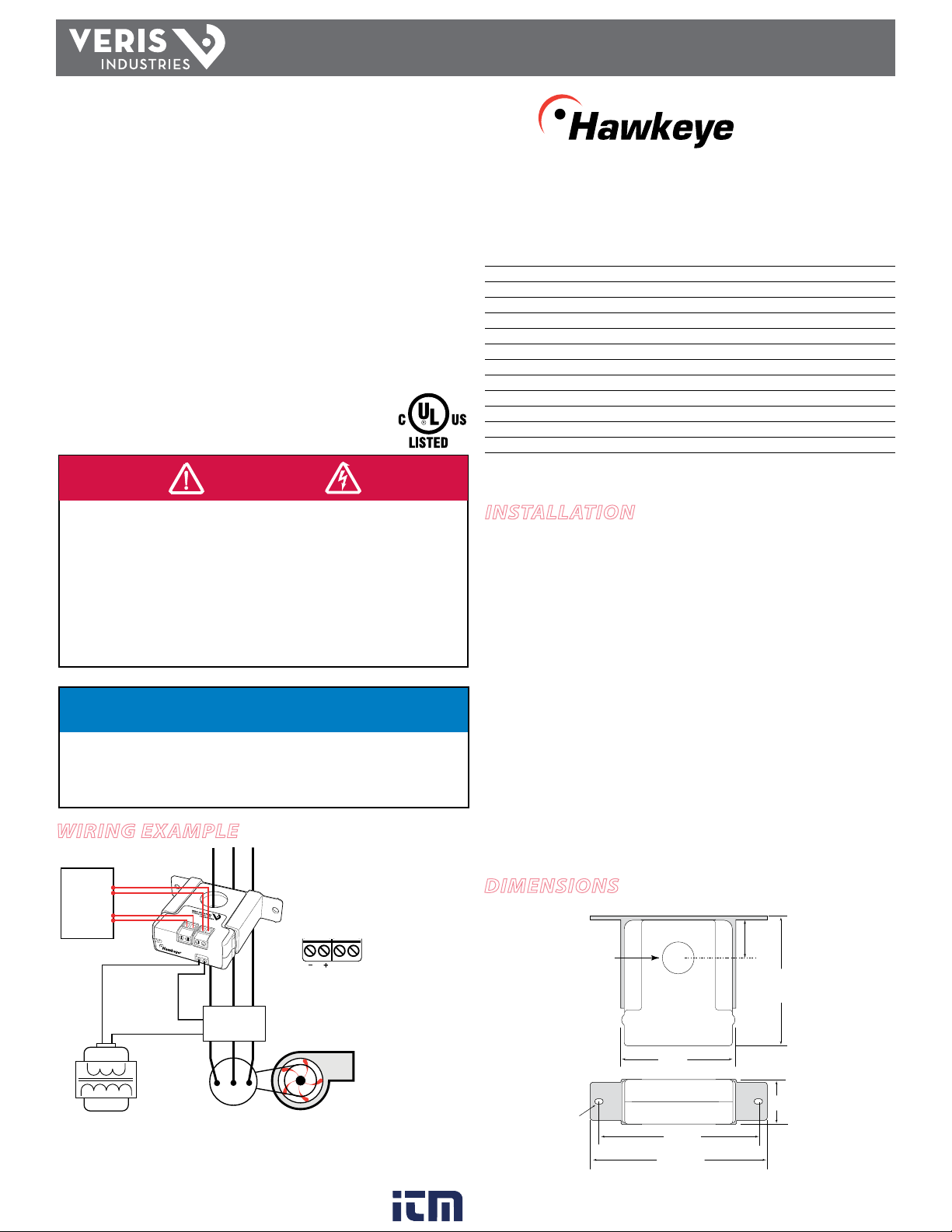
Wiring ExamplE
H740 TM 740
DimEnsions
NOTICE
• This product is not intended for life or safety applications.
• Do not install this product in hazardous or classified locations.
• The installer is responsible for conformance to all applicable codes.
• Mount this product inside a suitable fire and electrical enclosure.
installation
Disconnect and lock out power to the enclosure containing the
conductor to be monitored.
1. Locate a mounting surface for the removable mounting bracket that will allow
the monitored conductor to pass through the center window when it is installed
and that will keep the device at least 1/2” from any uninsulated conductors.
Determine cable routing for the controller connection, allowing wiring to reach
the mounting location.
2. Drill holes to mount the bracket to the chosen surface using the included screws.
3. Wire the output connections and relay between the sensor and the controller
(solid-state contact).
4. Wire sensor to control power.
5. Route the conductor through the sensor’s center window and slip the assembly
into the mounting bracket.
6. Secure enclosure and reconnect power.
0.2”x 0.15”
slot (2x)
1.1"
(27 mm)
2.8"
(68 mm)
0.7"
(19 mm)
0.9"
(23 mm)
3.0"
(75 mm)
Removable/Adjustable Mounting Bracket
3.8"
(95 mm)
4.2"
(106 mm)
Fan or Pump
Digital Control
DI (Status)
DO (Relay
Coil)
Control
Power
730
RELAYCOIL 1.0A@30VAC/DC
STATUS
OUTPUT
24VAC/DC
* Observe this polarity
when connecting the
relay coil to DC Voltage.
RELAY COIL
Motor
CONTACTOR
www. .com information@itm.com1.800.561.8187


