Veriton X4230G User manual

I
Veriton X4230G(VX4230G)
Lifecycle Extension Guide

Disassembly Procedure ..............................................................................................................3
Troubleshooting........................................................................................................................15
Exploded Diagrams...................................................................................................................18
FRU (Field Replaceable Unit) List...........................................................................................20
To update your software ........................................................................................................21
To remove your personal data ..............................................................................................21

3
Disassembly Procedure
Safety Guidelines
This chapter contains step by step procedures on how to remove and de-install components from
the computer. Use the following safety guidelines to ensure your personal safety. Each procedure
included in this chapter assumes that you are preparing your computer for recycling and disposal.
By performing any of these procedures you acknowledge that any remaining warranty applicable
to your computer will be voided. Before you start any of the procedures in this chapter, make
sure to read the following safety guidelines and the respective instructions within the chapter.
CAUTION!
Turn off your computer and disconnect all power sources before opening the computer
cover or panels.
To avoid electrostatic discharge, ground yourself by using a wrist grounding strap or by
periodically touching an unpainted metal surface at the same time as touching a connector
on the back of the computer.
Take off any metal objects on your arms or fingers such as bracelets, rings or watches and
make sure your hands are completely dry. Even if your unit is unplugged, there may still be
some remaining electric charge.
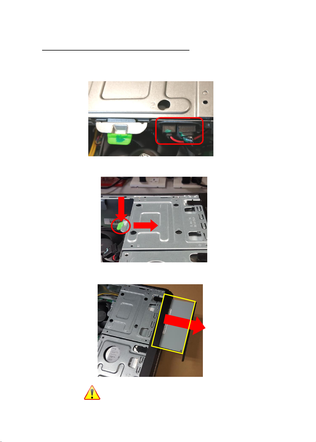
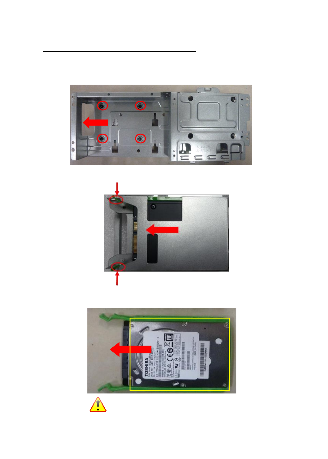
If a component does not come out easily, do not forcefully remove it. Instead, check that you
are removing it correctly and that no wires or other parts are in the way.
When you disconnect a cable, pull on its connector or on its pull-tab, not on the cable itself.
Some cables have connectors with locking tabs; if you are disconnecting this type of cable,
press in on the locking tabs before you disconnect the cable.
Recommended Equipment
The following equipment are recommended to do the following maintenance procedures:
Wrist grounding strap and conductivemat
Flat screwdriver
Philips screwdriver
Polydrive screwdriver
Plastic tweezers
Flat plastic pry

4
NOTE:
WEEE Annex VII Component
These
components are classified as requiring selective treatment.
Pre-disassembly Instructions
Do the following prior to starting any maintenance procedures:
1.
Place the system on a stable work surface.
2.
Remove AC power cord from the system and peripherals
3.
Remove all cables from the system.
Make sure the system is completely powered off.

5
Chassis Door Removal
1. Remove the chassis door
1.1 Remove the 2 screws
1.2 Remove the left side cover

6
ODD Removal
2. Remove the Slim ODD
2.1 Disconnect the ODD SATA cable and ODD power-cable
2.2 Press the tail of ODD to pushing it out of chassis
2.3 Remove the ODD
NOTE: ODD has been highlighted with the
yellow circle as above image shows. WEEE
Annex VII component.

7
3.5”HDD Removal
3. Remove 3.5”HDD
3.1 Disconnect SATA cable and power cable from HDD
3.2 Remove two screws fastening HDD cage
3.3 Press the ODD cage down and pull it out

8
3.4 Pull green rack out from HDD cage
3.5 Remove HDD from green rack
NOTE: HDD has been highlighted with the
yellow circle as above image shows. WEEE
Annex VII component.

9
2.5”SSD Removal
4. Remove 2.5”SSD
4.1 Remove four screw and take out the metal bracket
4.2 Remove the green tool-less from metal bracket
4.3 Remove the 2.5’’SSD
NOTE: SSD has been highlighted with the
yellow circle as above image shows. WEEE
Annex VII component.

10
VGA card Removal
5. Remove VGA Card
5.1 Remove a screw and open the PCI bracket
5.2 Press the PCI slot latch down and lift up the VGA card
NOTE: VGA card has been highlighted with
the yellow circle as above image shows.
WEEE Annex VII component.

11
PSU Removal
6. Remove internal PSU
6.1 Cut the cable tie and disconnect the 4pin ATX_12V and 6pin ATX_ power cables form MB
6.2 Remove four screw fastening PSU and pull it out from chassis
6.3 Push the latch then take out the PSU
NOTE: PSU MB/PSU FAN/PSU CAPACITOR have
been highlighted with the yellow circle as above image
shows. WEEE Annex VII component.

12
MotherBoard, MEM, CPU, Cooler, WLAN, SSD, RTC Battery Removal
7. Remove the Main Board
7.1 Remove the acetic acid tape antenna from MB
7.2 Disconnect SATA and SATA-power cables from MB
7.3 Disconnect front panel cables from MB

13
7.4 Remove the eight screws from MB
7.5 Release the two latch show bellow then remove the Memory
7.6 Disconnect fan power cable from MB then remove CPU cooler
NOTE: Circuit boards >10 cm²has been highlighted with the
yellow rectangle as above image shows. WEEE Annex VII
component. Please detach the Circuit boards and follow local
regulations for disposal.
NOTE: CPU cooler has been highlighted with
the yellow circle as above image shows.
WEEE Annex VII component.
NOTE: MEMORY has been highlighted with the
yellow circle as above image shows. WEEE
Annex VII component.

14
7.7 Remove the CPU
7.8 Remove a screw fastening the M.2 SSD and pull it out of slot
7.9 Remove the battery
NOTE: RTC battery has been highlighted with
the yellow circle as above image shows.
WEEE Annex VII component.
NOTE: CPU has been highlighted with the
yellow circle as above image shows. WEEE
Annex VII component.
NOTE: SSD has been highlighted with the
yellow circle as above image shows. WEEE
Annex VII component.

15
Troubleshooting
This chapter provides troubleshooting information for the Veriton X4230G Service Guide
Power-On Self-Test (POST)
POST Error Messages List
Power-On Self-Test (POST)
Each time you turn on the system, the Power-on Self Test (POST) is initiated. Several items are tested during POST, but
for the most part transparent to the user.
The Power-On Self Test (POST) is a BIOS procedure that boots the system, initializes and diagnoses the system
components, and controls the operation of the power-on password option. If POST discovers errors in system
operations at power-on, it displays error messages on screen, generates a check point code at port 80h or even halts
the system if the error is fatal.
The main components on the main board that must be diagnosed and/or initialized by POST to ensure system
functionality are as follows:
Microprocessor with built-in numeric co-processor and cache memory subsystem
Direct Memory Access (DMA) controller
Interrupt system
Three programmable timers
ROM subsystem
RAM subsystem
CMOS RAM subsystem and real time clock/calendar with battery backup
Onboard parallel interface controller
Embedded hard disk interface and one diskette drive interface
Keyboard and auxiliary device controllers
I/O ports
One parallel port
One PS/2-compatible mouse port
One PS/2-compatible keyboard port

16
POST Error Messages List
If you cannot run the diagnostics program tests but did receive a POST error message, use “POST Error
Messages List "to diagnose system problems. If you did not receive any error message, look for a description of
your error symptoms in “Error Symptoms List”.
If you are unable to correct the problem by using the “BIOS Messages List” table and “Error Symptoms List” table,
go to “Undetermined Problems”.
To diagnose a problem, first find the BIOS error messages in the left column. If directed to a check procedure,
replace the FRU indicated in the check procedure. If no check procedure is indicated, the first Action/FRU listed in
right column is the most likely cause.
BIOS Messages
Action/FRU
BIOS ROM checksum
error - System halted
The checksum of the BIOS code in the BIOS chip is incorrect, indicating the BIOS code may
have become corrupt. Contact your system dealer to replace the BIOS.
CMOS Battery Failed
The CMOS battery is no longer functional. Contact your system dealer for a replacement
the BIOS.
CMOS Checksum
Error- defaults loaded
Checksum of CMOS is incorrect, so the system loads the default equipment configuration.
A checksum error may indicate that CMOS has become corrupt. A weak battery may have
caused this error. Check the battery and replace if necessary.
CPU at run
Displays the running speed of CPU.
Display switch is set
incorrectly
The display switch on the motherboard can be set to either monochrome or color. This
message indicates the switch is set to a different setting than indicated
in Setup. Determine which setting is correct, and
then either turn off the system and change the jumper, or enter Setup and change
the Video selection.
Press ESC to skip
memory test
The user may press Esc to skip the full memory test.
HARD DISK initializing
- Please wait a
moment
Some hard drives require extra time to initialize.
HARD DISK INSTALL
FAILURE
Cannot find or initialize the hard drive controller or the drive. Make sure the controller is
installed correctly. If no hard drives are installed, be sure the Hard Drive Selection in Setup
is set to NONE.
Hard disk(s) diagnosis
fail
The system may run specific disk diagnostic
Routines. This message appears if one or more hard disks return an error when the
diagnostics run.
Keyboard Error Or No
Keyboard Present
Cannot initialize the keyboard. Make sure the keyboard is attached correctly and no keys
are pressed during POST. To purposely configure the system without a keyboard, set the
error halt condition in Setup to HALT ON ALL, BUT KEYBOARD. The BIOS then ignores the
missing keyboard during POST.
Keyboard is locked out
- Unlock the key
This message usually indicates that one or more keys have been pressed during the
keyboard tests. Be sure no objects are resting on the keyboard.

17
BIOS Messages
Action/FRU
Memory Test:
This message displays during a full memory test, counting down the memory areas being
tested.
Memory test fail
If POST detects an error during memory testing, additional information appears giving
specifics about the type and location of the memory error.
Override enabled -
Defaults loaded
If the system cannot boot using the current CMOS configuration, the BIOS can override the
current configuration with a set of BIOS defaults designed for the most stable, minimal-
performance system operations.
Press TAB to show
POST screen
System OEMs may replace the Phoenix Technologies Award BIOS POST display with their
own proprietary display. Including this message in the OEM display permits the operator to
switch between the OEM display and the default POST display.
Primary master hard
disk fail
POST detects an error in the primary master hard drive.
Primary slave hard
disk fail
POST detects an error in the secondary master hard drive.
Secondary master
hard disk fail
POST detects an error in the primary slave hard drive.
Secondary slave hard
disk fail
POST detects an error in the secondary slave hard drive.

18
Exploded Diagrams
Figure 1 System Exploded Diagram

19
Item
Description
Item
Description
1
Rubber foot
26
LED sponge
2
Black Screw
27
Power sponge
3
Side Cover L
28
Power switch PCB
4
HDD Bracket
29
MB Rubber
5
HDD Top cover
30
#6-32*5 Screw
6
#6-32*5 Screw
31
HDD support Bracket
7
HDD support Bracket
32
HDD Rubber
8
ODD Bracket
33
HDD tool-less
9
Rivet-1
34
HDD lens
10
Rivet-2
35
Power lens
11
X5.1 Side bkt
36
IO Cover
12
PCI Cover
37
ADHESIVE for IO Cover
13
Gasket
38
Power button
14
Metal Cable Clip
39
VX logo strip
15
MB Bracket
40
VX Front Bezel
16
M2*8 Screw
17
INTERNAL INTRUSION ALARM
18
M2*5 Screw
19
INTRUSION Bracket
20
Bottom Bracket
21
FIO Mylar
22
#6-32*5 Screw
23
FIO Bracket
24
SM Bracket
25
SD Bracket

20
FRU (Field Replaceable Unit) List
Please contact your local service center to find out how to obtain the part or replace your device
This manual suits for next models
1
Table of contents