Verland Titan T3000 User manual

OverlandTandberg.com
INSTALLATION GUIDE
Titan T3000
Installation and
Storage Expansion Guide
© Dell Technologies

Dell EMC PowerProtect DD6400 System
Installation and Storage Expansion Guide
February 2022
Rev. 04

Notes, cautions, and warnings
NOTE: A NOTE indicates important information that helps you make better use of your product.
CAUTION: A CAUTION indicates either potential damage to hardware or loss of data and tells you how to avoid
the problem.
WARNING: A WARNING indicates a potential for property damage, personal injury, or death.
© 2021 - 2022 Dell Inc. or its subsidiaries. All rights reserved. Dell, EMC, and other trademarks are trademarks of Dell Inc. or its subsidiaries.
Other trademarks may be trademarks of their respective owners.

Figures..........................................................................................................................................5
Tables........................................................................................................................................... 6
Chapter 1: Introduction and Preparation........................................................................................ 7
Upgrade Requirement for Data Domain OS Version 7.7.0 on DD6400 Units........................................................7
Document purpose.............................................................................................................................................................. 8
Installation checklist............................................................................................................................................................8
DD6400 system features...................................................................................................................................................8
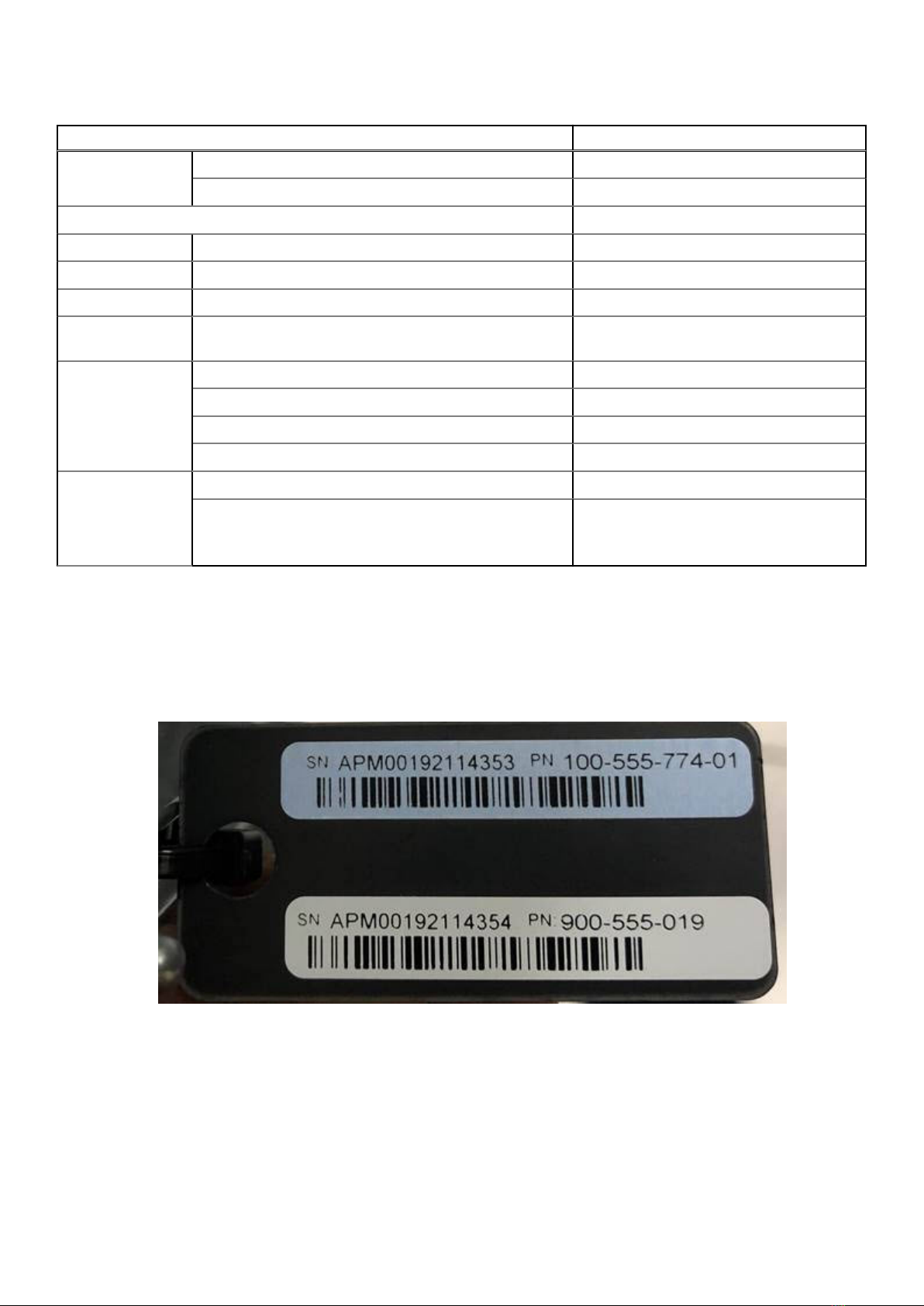
Product serial number tag (PSNT)................................................................................................................................. 9
Required tools and supplies ............................................................................................................................................10
Safety considerations........................................................................................................................................................ 11
Chapter 2: Install the System in the Rack.................................................................................... 12
Identifying the rail kit components................................................................................................................................ 12
Install the rails..................................................................................................................................................................... 13
Secure the rail assemblies to the cabinet.................................................................................................................... 14
Install the system in the cabinet.................................................................................................................................... 15
Install the front bezel........................................................................................................................................................ 16
Install the CMA arm........................................................................................................................................................... 17
Chapter 3: Install the Disk Shelves in the Rack............................................................................ 19
Remove filler panels.......................................................................................................................................................... 19
Install an ES40 shelf into the rack................................................................................................................................. 19
Installing the rails in the cabinet............................................................................................................................... 19
Installing the shelf on the rails..................................................................................................................................22
Installing and locking the front bezel......................................................................................................................23
Chapter 4: Connect Cables and Power On................................................................................... 25
Connecting ES40 shelves................................................................................................................................................26
DD6400 with ES40 cabling............................................................................................................................................. 26
Connecting data cables....................................................................................................................................................27
Connecting disk shelf power cables............................................................................................................................. 28
Connecting controller power cables and powering on.............................................................................................29
Chapter 5: Configure System for Use.......................................................................................... 30
Configure iDRAC............................................................................................................................................................... 30
Configure serial over LAN (SOL)...................................................................................................................................32
Change the iDRAC network port...................................................................................................................................33
Enable administrative communication.......................................................................................................................... 33
Accepting the End User License Agreement..............................................................................................................34
Run the configuration wizard......................................................................................................................................... 35
Configuring the network............................................................................................................................................35
Configuring additional system parameters............................................................................................................ 37
Configuring the system with the configuration wizard............................................................................................38
Contents
Contents 3

License................................................................................................................................................................................. 38
Network............................................................................................................................................................................... 38
Passphrase..........................................................................................................................................................................38
File System..........................................................................................................................................................................39
Settings................................................................................................................................................................................39
Selecting and configuring Secure Remote Services delivery................................................................................. 39
CLI equivalent...............................................................................................................................................................40
Chapter 6: Installation Troubleshooting....................................................................................... 41
Installation troubleshooting scenarios...........................................................................................................................41
Appendix A: Add Storage Capacity...............................................................................................43
Prepare system for storage expansion........................................................................................................................ 43
Install and connect the new storage............................................................................................................................ 43
Verify and configure the new disks...............................................................................................................................44
License the new storage with electronic licensing................................................................................................... 45
Expand the file system.....................................................................................................................................................45
4 Contents

1 Rear tag........................................................................................................................................................................ 9
2 Front tag.....................................................................................................................................................................10
3 Serial number for initial password........................................................................................................................ 10
4 Sliding rail assembly - 2U systems....................................................................................................................... 12
5 CMA arm and separator..........................................................................................................................................13
6 Installing the rear end of the rail...........................................................................................................................13
7 Installing the front end of the rail......................................................................................................................... 14
8 Installing screws........................................................................................................................................................14
9 Pull out the intermediate rail..................................................................................................................................15
10 Attach the inner rails to the system.................................................................................................................... 15
11 Install system into the extended rails.................................................................................................................. 16
12 Slide system into the rack...................................................................................................................................... 16
13 Installing the front bezel......................................................................................................................................... 17
14 Install the seperator................................................................................................................................................. 17
15 Install the arm............................................................................................................................................................18
16 Close the arm............................................................................................................................................................ 18
17 Holes for alignment pins......................................................................................................................................... 21
18 Installing the rails..................................................................................................................................................... 22
19 Sliding the shelf onto the rails.............................................................................................................................. 22
20 Securing the front of the shelf.............................................................................................................................23
21 Installing the front bezel........................................................................................................................................ 24
22 DD6400 with one ES40 shelf................................................................................................................................26
23 DD6400 with two ES40 shelves...........................................................................................................................27
24 Slot numbering..........................................................................................................................................................27
25 ES40 power cabling................................................................................................................................................ 29
26 iDRAC Settings > Network.................................................................................................................................... 31
27 iDRAC Settings > User Configuration................................................................................................................. 31
Figures
Figures 5

1 DD6400 system features......................................................................................................................................... 8
2 DD6400 with one ES40 cabling instructions.................................................................................................... 26
3 DD6400 with two ES40s: DD6400 to ES40s cabling instructions.............................................................. 26
4 DD6400 with two ES40s: ES40 to ES40 cabling instructions...................................................................... 27
5 I/O Module Slot assignments............................................................................................................................... 28
6 Maximum FC cable lengths................................................................................................................................... 28
7 iDRAC NIC to physical port mapping.................................................................................................................. 33
8 Communications settings.......................................................................................................................................33
9 Settings page values............................................................................................................................................... 39
10 Troubleshooting scenarios......................................................................................................................................41
Tables
6 Tables

Introduction and Preparation
Topics:
•Upgrade Requirement for Data Domain OS Version 7.7.0 on DD6400 Units
•Document purpose
•Installation checklist
•DD6400 system features
•Product serial number tag (PSNT)
•Required tools and supplies
•Safety considerations
Upgrade Requirement for Data Domain OS Version
7.7.0 on DD6400 Units
Data Domain 6400 systems come pre-installed with the latest version of the Data Domain OS software that was available from
the factory at the time of shipment. As a standard practice, Dell Technologies requires that customers with new installations
download the latest available code version at the time of install.
Data Domain OS version 7.7.0 may be susceptible to an issue that could result in an impact to data availability. Data Domain OS
version 7.7.1 contains a fix that addresses this issue.
Required Action
Upon installation of the Data Domain 6400 system, you are required to immediately perform a pre-upgrade health check, and
upgrade to Data Domain OS version 7.7.1. This version may be downloaded from the DD OS 7.7 Drivers & Downloads section
on the Data Domain Product Support page https://www.dell.com/support/home/en-us/product-support/product/dd-os-7.7/
drivers
For complete instructions on updating your Data Domain OS, refer to the Dell EMC Data Domain Software Upgrade in KB 21710
- https://www.dell.com/support/kbdoc/000021710.
If you do not take action at this time, please be advised that the system may encounter an
issue which could result in an impact to data availability. Dell is not responsible for any
data unavailability.
Further Assistance
As always, Dell Technologies continues to stand behind the warranty and service contracts applicable to your systems.
If you need further assistance or have any other questions, contact Dell Technologies technical support. Dell Technologies
provides several online and telephone-based support and services options. Availability varies by country and product, and some
services may not be available in your area.
To contact Dell Technologies technical support:
1. Go to https://dell.com/support.
2. Select the contact method that best suits your needs.
3. Reference Dell knowledgebase article KB195329 - https://www.dell.com/support/kbdoc/000195329 for this issue.
1
Introduction and Preparation 7

Document purpose
This installation guide provides instructions for installing the hardware associated with PowerProtect systems. Systems are
shipped to the customer site as separate components to install in an existing rack at the site (field-installed).
This document is intended for customers or Dell EMC Support personnel who are qualified to install PowerProtect systems.
Field-installed systems
To install PowerProtect systems in an existing rack at the customer site, follow all the instructions in this document to rack,
cable, and configure the system.
Installation checklist
This section lists prerequisites and best practices for installing a PowerProtect DD6400 system.
Review the following table before installing the DD6400.
Requirement Description
Rack space ●DD6400 controller only: 2U
●DD6400 controller with one ES40: 5U
●DD6400 controller with two ES40s: 8U
Rack power connections Minimum of two redundant PDUs
Networking ●System hostname
●Minimum of two IP addresses:
○iDRAC (static IP address required)
○ethMa
●List of DNS servers
Licenses Electronic license file for the proper DDOS version, storage
capacity, and feature selection.
DD6400 system features
Table 1. DD6400 system features
Feature Single Node
Processor 2 x Intel Xeon Silver, 2.2 Ghz, 10C/20T
Kernel 4.4
Memory
Configurations
Total 192 GB
DIMMs 12 x 16 GB
HDD Drive Size 8 TB
Supported
Capacity
Active Tier Base 8 <-> 32 TBu
Expanded 36 <-> 172 TBu
Cloud Tier Base 64 TBu
Expanded 344 TBu
SSDs for DD OS in 2.5" 2, 0.96 TB, 1 WPD
Stream Count 270 Wr, 75 Rd
8 Introduction and Preparation

Table 1. DD6400 system features (continued)
Feature Single Node
Cache SSDs Base (6% of 32 TBu) 1 (Internal) 1.92 TB
Expanded (2.2% of 172 TBU) 2 (Internal) 1.92 TB
16 GB NVRAM 1
HW Accelerator Quick Assist Technology (QAT) 8970 1
Internal SAS HBA330 12 Gbps SAS controller 1
External SAS Dual Port 12 Gbps SAS 1
SAS String Depth
(max)
ES40 2
Host interface 2-port 25 GbE-SFP28 3 maximum
4-port 10 GbE-SFP+ 3 maximum
4-port 10GBASE-T 3 maximum
4-port 16 Gb FC 1 maximum
Network Daughter
Card option
(system will have
one of the two
options)
4-port 10 GbE-SFP+ 1
4-port 10GBASE-T 1
Product serial number tag (PSNT)
The PSNT provides the system serial number that is used as the initial administrator password for DD OS.
The system serial number is included in two places on the system:
●A small tag clipped to the back of the system, on the left side of the rear handle.
Figure 1. Rear tag
●A larger tag recessed into the front of the chassis on the right-hand side
Introduction and Preparation 9

Figure 2. Front tag
There are two labels on each tag:
●The top label is blue and contains the serial number for the system top level assembly (TLA).
●The bottom label is white and contains the product serial number required for the initial password.
Figure 3. Serial number for initial password
Required tools and supplies
Ensure that you have the required tools and supplies on hand for the PowerProtect system installation.
You will need:
●Antistatic wrist strap and conductive foam pad
●Screwdrivers:
○Phillips #1
○Phillips #2 with a 4- to 6-inch blade and a magnetic tip
○Phillips #2 with a 12 in. or longer blade and magnetic tip
○Flat head with a 3/16 in. blade
○Flat head with a 1/4 in. blade
○Torque
●Flashlight (free-standing for single-person installations)
●Roll of 5/8 inch Velcro cable tie material (3M Scotchmate SJ-3401 or similar)
●Null modem cable with DB-9 female connector to connect a service laptop to the PowerProtect system.
The following additional tools and supplies might be needed when working with PowerProtect systems:
●Torque screwdriver
10 Introduction and Preparation

●Pliers
○Needle nose
○Regular
○Locking
●10 mm socket or wrench
●Diagonal wire cutters (for cutting tie wraps)
●exFAT formatted 4 GB or greater USB flash memory drive
●Tie wraps (4 in. and 8 in.)
●Labels
●Pen or marker
●Masking tape
Safety considerations
Always follow safety recommendations to avoid damage to the system or harm to personnel.
CAUTION:
●If the system is used in a manner not specified by the manufacturer, the protection provided by the
equipment could be impaired.
●The RJ45 ports on the motherboard, PCI cards, or I/O modules are for Ethernet connection only and must
not be connected to a telecommunications network.
CAUTION: Improper installation on the rails may damage the rails or cause the system to fall when extended.
When extending the system from the rack, pull outward slowly and verify the system is properly installed on the
rails.
Review and follow these important safety recommendations:
●For ESD protection, Dell EMC recommends that you wear a suitable antistatic wrist or ankle strap. Observe all conventional
ESD precautions when handling plug-in modules and components.
●All plug-in modules and blank plates are part of the fire enclosure system and should not be removed unless a replacement
can be added immediately. Do not run the system without all parts in place.
●Provide a suitable power source with electrical overload protection.
●Provide a safe electrical ground connection to each power cord. Check the grounding of the power sources before applying
power.
●A DD6400 system must be operated only from a power supply input voltage range of 100–240 VAC and 50–60 Hz.
●ES40 shelves use 100–240 VAC and 47–63 Hz.
●The system is intended to operate with all installed power supplies working as designed.
●A faulty power supply module should be replaced within 24 hours.
●Always disconnect the power connections before removing or replacing a power supply module.
●The main way to disconnect power from the system is to unplug the power supply cord.
●The system includes two power supplies. To completely remove system power, you must disconnect both power supplies.
●Always disconnect the power connections before moving the system.
●If you think the unit is damaged in any way, permanently unplug it.
●CAUTION: The system components are heavy. To avoid personal injury and/or damage to the equipment,
do not attempt to install or remove system components without a mechanical lift and/or help from another
person.
○A DD6400 system weighs up to 63.05 lbs (28.6 kg).
○ES40 shelves weigh up to 68 lbs (30.8 kg).
Introduction and Preparation 11

Install the System in the Rack
CAUTION: Improper installation on the rails may damage the rails or cause the system to fall when extended.
When extending the system from the rack, pull outward slowly and verify the system is properly installed on the
rails.
Topics:
•Identifying the rail kit components
•Install the rails
•Secure the rail assemblies to the cabinet
•Install the system in the cabinet
•Install the front bezel
•Install the CMA arm
Identifying the rail kit components
The 2U sliding rail assemblies allow the server to be secured in the cabinet, and extended from the cabinet so that the system
cover can be removed to access the internal FRUs.
Figure 4. Sliding rail assembly - 2U systems
1. Sliding rail (2)
2. Velcro strap (2)
3. Screw (4)
4. Washer (4)
The rails are compatible with racks with square holes, unthreaded round holes, and threaded round holes.
The CMA assembly consists of one articulated arm, and one separator.
2
12 Install the System in the Rack

Figure 5. CMA arm and separator
Install the rails
About this task
The rails are labeled left and right, and cannot be interchanged. The front side of each rail is labeled Left Front or Right Front
when viewed from the cabinet front.
Steps
1. Determine where to mount the system, and use masking tape or a felt-tip pen to mark the location at the front and back of
the cabinet.
NOTE: Install the left rail assembly first.
2. Fully extend the rear sliding bracket of the rail.
3. Position the rail end piece labeled Left Front facing inward and orient the rear end piece to align with the holes on the rear
cabinet flanges.
4. Push the rail straight toward the rear of the rack until the latch locks in place.
Figure 6. Installing the rear end of the rail
5. For the front end piece, rotate the latch outward and pull the rail forward until the pins slide into the flange, and release the
latch to secure the rail in place.
Install the System in the Rack 13

Figure 7. Installing the front end of the rail
6. Repeat the preceding steps to install the right rail assembly.
Secure the rail assemblies to the cabinet
The supplied screws and washers are used to secure the rail assemblies to the front and rear of the cabinet.
About this task
NOTE: For square hole cabinets, install the supplied conical washer before installing the screw. For unthreaded round hole
cabinets, install only the screw without the conical washer.
Steps
1. Align the screws with the designated U spaces on the front and rear rack flanges.
Ensure that the screw holes on the tab of the system retention bracket are seated on the designated U spaces.
2. Insert and tighten the two screws using the Phillips #2 screwdriver.
Figure 8. Installing screws
14 Install the System in the Rack

Install the system in the cabinet
In an angled drop-in design, inner (chassis) rails are attached to the sides of the system and then the system slides into the
outer (cabinet) rails that are installed in the rack.
About this task
WARNING: The system is heavy. To avoid personal injury and/or damage to the equipment, do not attempt to
install the system in a cabinet without a mechanical lift and/or help from another person.
Steps
1. Pull the inner rails out of the rack until they lock into place.
2. Release the inner rail lock by pulling forward on the white tabs and sliding the inner rail out of the intermediate rails.
Figure 9. Pull out the intermediate rail
1. Intermediate rail
2. Inner rail
3. Attach the inner rails to the sides of the system by aligning the J-slots on the rail with the standoffs on the system and
sliding forward on the system until they lock into place.
Figure 10. Attach the inner rails to the system
4. Verify all the J-slots on the rails are aligned with the rail standoffs on the system.
Install the System in the Rack 15

CAUTION: Improper installation on the rails may damage the rails or cause the system to fall when extended.
5. With the intermediate rails extended, install the system into the extended rails.
Figure 11. Install system into the extended rails
6. Pull the blue slide release lock tabs forward on both the rails, and slide the system into the rack.
Figure 12. Slide system into the rack
Install the front bezel
The procedure to install the front bezel with the LCD panel and the front bezel without the LCD panel is the same.
Steps
1. Align and insert the right end of the bezel onto the system.
2. Press the release button and fit the left end of the bezel onto the system.
3. Lock the bezel by using the key.
16 Install the System in the Rack

Figure 13. Installing the front bezel
Install the CMA arm
Steps
1. Install the separator on the bracket.
Figure 14. Install the seperator
2. Install the arm on the right side of the chassis, on top of the separator with the open side up.
Install the System in the Rack 17

Figure 15. Install the arm
3. Close the arm by connecting it to the bracket on the left side of the chassis.
Figure 16. Close the arm
18 Install the System in the Rack

Install the Disk Shelves in the Rack
Topics:
•Remove filler panels
•Install an ES40 shelf into the rack
Remove filler panels
The front space of the rack into which you will install the shelf is usually covered by a filler panel. If one or more filler panels
cover the space where you want to install the shelf, use this procedure to remove each panel.
Steps
1. On the filler panel, slide the left and right securing tabs to the open position (towards the center of the panel).
2. Remove the filler panel from the cabinet.
Install an ES40 shelf into the rack
Follow the steps in this section to install the rails, ES40 expansion shelf, and bezel. Follow these steps for each ES40 shelf you
are installing.
There are no specific placement requirements for the ES40 shelves in relation to the DD6400 controller in the rack, as long as
they are close enough to be connected by cables no longer than five meters.
NOTE: The included cables are one meter. Three and five meter cables are optional lengths.
Installing the rails in the cabinet
About this task
The rails are compatible with racks with square holes, unthreaded round holes, and threaded round holes.
NOTE: The front edge of each rail is stamped L or R for left or right side with the rail facing the cabinet front.
Install each rail in the cabinet.
3
Install the Disk Shelves in the Rack 19
Table of contents
Popular Server manuals by other brands

Dell
Dell PowerEdge 1650 Information update

Gigabit Sistems
Gigabit Sistems MFPR-3100 instruction manual

TRENDnet
TRENDnet TV-IP100W-N - Wireless Internet Camera Server... Specifications

Dell
Dell 8 Getting started guide

Allnet
Allnet FW8888+ Quick installation guide

Sun Microsystems
Sun Microsystems Sun Fire V1280 Site preparation and installation guide