Versa Technology VX-VEB160G4 User manual

VX-VEB160G4 (V3) 300Mbps Ethernet Extender Kit
User Manual
Version 1.0
08/05/2020

VX-VEB160G4(V3) LITE INDUSTRIAL VDSL2 ETHERNET
EXTENDER - UM V1.0
I
Table of Contents
Introduction............................................................................................................................1
1.1 Features ..........................................................................................................................1
1.2 Specifications..................................................................................................................2
1.3 Mechanical Dimensions..................................................................................................2
1.4 Installation Procedure .....................................................................................................3
1.5 Reference Performance Data.........................................................................................3
Hardware Description............................................................................................................2
2.1 Connector Architecture ...................................................................................................2
2.2 Installation Accessory .....................................................................................................3
2.3 DIN Rail Mounting...........................................................................................................4
LED Definition ........................................................................................................................5
3.1 LED Indicators.................................................................................................................5
Power Connection .................................................................................................................6
4-Position DIP Switch............................................................................................................7
Description of Setting ...........................................................................................................8

VX-VEB160G4(V3) LITE INDUSTRIAL VDSL2 ETHERNET
EXTENDER - UM V1.0
1
Introduction
Versa Technology’s VX-VEB160G4 (V3) is a Lite Industrial Grade Ultra-Speed Gigabit
Ethernet Copper Extender that supports a remarkable aggregated bandwidth up to
300Mbps (Downstream: 150 Mbps/Upstream: 150 Mbps). It delivers fiber-optic like speeds
on existing copper infrastructure, enabling a good alternative in place where fiber is not
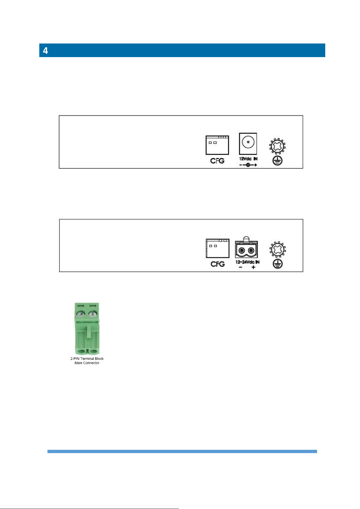
economical to deploy. The VX-VEB160G4 (V3) is equipped with four Gigabit Ethernet Ports
(RJ-45 connector) and one VDSL2 port (RJ-45 connector or 2-PIN Terminal Block) in metal
enclosure for easy installation in harsh environment. There are 8 different profile settings
which can be flexibly selected via DIP switch to suit various applications and environments.
Symmetric profile can be applied as a standard Ethernet connection while Asymmetric profile
can be used for other services like video streaming or IP surveillance services which require
high traffic flow in an uni-direction configuration. The VX-VEB160G4 (V3) supports
transparent LAN bridging to extend Ethernet service over UTP, Cat 5+ or Coaxial cables.
Versa Technology’s VX-VEB160G4 (V3) has superior performance in its category. It is the
best high throughput Long Reach Ethernet Extender for service providers to deploy their IP-
based networking services to meet various application scenarios in harsh environments.
1.1 Features
⚫High speed Ethernet extension over UTP, CAT 5e/6/7 or Coaxial cables.
⚫Support ITU-T G.993.5 G.vectoring and G.INP
⚫Selectable 8 different profile settings via DIP Switch (G.INP/Interleaved, Target SNR
6/8/12/24 dB, Symmetric/Asymmetric Modes)
⚫Support wide operating temperature range
⚫Cost effective bridge function to connect two Ethernet LAN
⚫IEEE 802.1Q VLAN tag transparent
⚫Easy installation via simple plug-and-play in harsh environment

VX-VEB160G4(V3) LITE INDUSTRIAL VDSL2 ETHERNET
EXTENDER - UM V1.0
2
1.2 Specifications
VDSL Interface
⚫RJ-45 connector or 2-PIN Terminal Block
⚫DMT Encoding
⚫Complying with ITU-T
G993.1/G993.2/G993.5/G.997.1/G.998
⚫G.INP
⚫On-board surge protection
LAN Interface
⚫4 x RJ-45 connectors
⚫10/100/1000 Base-T; Auto-Negotiation,
Auto-MDI/MDI-X.
⚫Complying with IEEE 802.3/802.3u/802.3z
4-position DIP Switch
⚫Selectable Master (OT) or Remote (RT)
mode
⚫Selectable 8 different profile settings via
DIP Switch (G.INP/Interleaved, Target
SNR 6/8/12/24 dB,
Symmetric/Asymmetric Modes)
LED
⚫Power: On/Off
⚫LAN: Fast Ethernet/Gigabit Ethernet
⚫VDSL2: Mode – CO (OT) / CPE (RT)
Sync - Idle / Trained / Link
Power supply
⚫VX-VEB160G4 (V3)-AC: 12V DC over 2.1mm DC
Jack (Commercial Grade External Power Adaptor
included)
⚫VX-VEB160G4 (V3)-DC: 12~24V (7.5-30 Max)
DC over Terminal Block
⚫Power Consumption: 4.5 Watts maximum
Physical Characteristics
⚫Dimension (WxHxD): 130 x 28 x 94.7 mm
⚫Installation: DIN Rail
Environment
⚫Operating Temperature: -20°C ~65°C
⚫Humidity: 0%~95%RH (non-condensing)
Regulatory Compliance
⚫CE Class A
⚫FCC Part 15B Class A
⚫EN62368-1
1.3 Mechanical Dimensions
*The mechanical dimensions includes the layout of the DIN Rail.

VX-VEB160G4(V3) LITE INDUSTRIAL VDSL2 ETHERNET
EXTENDER - UM V1.0
3
1.4 Installation Procedure
The solution works in pairs for point to point connectivity. One unit must be configured as
Master (OT) while the other unit must be configured as Remote (RT) by using DIP Switch.
●STEP 1:
Set the LAN extender to CO mode or CPE mode from the DIP Switch at the front panel. For
Point to Point applications, one unit must be Master (CO mode) and the other one is Slave
(CPE mode).
●STEP 2:
Connect the LAN extender (CPE) with a regular Cat. 5 cable to the LAN port from a PC or
another device on LAN.
●STEP 3:
Power on LAN extender (CPE) by connecting the power adapter.
●STEP 4:
Connect the CPE and CO via a regular Cat. 5 cable or a telephone wire from each VDSL2
port.
●STEP 5:
Connect the LAN extender (CO) with a regular Cat. 5 cable to the LAN port and then connect
the other end of the RJ45 cable to the service equipment.
●STEP 6:
Power on LAN extender (CO) by connecting the power adapter and then observe the status
of VDSL link LED.
1.5 Reference Performance Data
26AWG Copper Wire
UTP, 26AWG
UTP, 26AWG
Profile Setting 1:
Symmetric, SNR 8dB, G.INP
Profile Setting 1:
Asymmetric, SNR 8dB, G.INP
Distance
(Feet)
Upstream
Line Rate
(Mbps)
Downstream
Line Rate
(Mbps)
Distance
(Feet)
Upstream
Line Rate
(Mbps)
Downstream
Line Rate
(Mbps)
500
155
158
500
100
200
1,000
122
126
1,000
77
170
1,500
75
80
1,500
38
105
2,000
48
56
2,000
22
64
2,500
28
38
2,500
10
43
3,000
23
28
3,000
9
42
* The above performance data is for reference only, the actual data rate may vary depending on the quality of the copper wire and environmental
factors.

VX-VEB160G4(V3) LITE INDUSTRIAL VDSL2 ETHERNET
EXTENDER - UM V1.0
2
Hardware Description
This chapter shows the hardware connector, and installation accessory.
2.1 Connector Architecture
Ethernet Port Connector
(RJ-45)
The Ethernet Port interface is an 8-position Modular Jack. The table below displays the pin out
assignments.
Pin Number
Name
Description
1
BI_DA+
Bi-directional pair A +
2
BI_DA-
Bi-directional pair A -
3
BI_DB+
Bi-directional pair B +
4
BI_DC+
Bi-directional pair C +
5
BI_DC-
Bi-directional pair C -
6
BI_DB-
Bi-directional pair B -
7
BI_DD+
Bi-directional pair D +
8
BI_DD-
Bi-directional pair D -

VX-VEB160G4(V3) LITE INDUSTRIAL VDSL2 ETHERNET
EXTENDER - UM V1.0
3
VDSL Interface Pin Assignments (RJ-45)
The VDSL interface is standard eight-pin modular jack. The table below displays the pin out
assignments.
Pin Number
Desc
r
i
p
t
io
n
Figure
1
Not used
18
Top View
18
Front View
2
Not used
3
Not used
4
ANALOG Input /Output
5
ANALOG Input /Output
6
Not used
7
Not used
8
Not used
2.2 Installation Accessory
DIN Rail Accessory:
●Fasten the DIN Rail clip to the device using a screwdriver and three machine screws.
●The diameter of each screw is 3mm and the length of each screw is 5mm.

VX-VEB160G4(V3) LITE INDUSTRIAL VDSL2 ETHERNET
EXTENDER - UM V1.0
4
2.3 DIN Rail Mounting
◼Mounting Step
STEP 1: Hook the unit over the DIN Rail.
STEP 2: Push the bottom of the unit towards the DIN Rail until it snaps into place.
◼Removal Step
STEP 1: Push the unit down to free the bottom of the DIN Rail.
STEP 2: Rotate the bottom of the unit away from the DIN Rail.
STEP 3: Unhook top of unit from DIN Rail.

VX-VEB160G4(V3) LITE INDUSTRIAL VDSL2 ETHERNET
EXTENDER - UM V1.0
5
LED Definition
3.1 LED Indicators
The LED indicators could provide instant feedback to users; the behaviors of the LED are given
in below table.
(1) LEDs for VDSL
LED
Color
Blinking
On
Off
PWR
Green
Device Power
On
Device Power Off
RT
Green
CPE (Remote)
CO (Master)
LNK
Green
Slow: Idle
Fast: Training /
Data Transmitting
Link UP
Link Down
(2) LEDs for Ethernet Port
LED
Color
Blinking
On
Off
10/100
Yellow
Data Transmitting
Link at speed of
10/100 Mbps
Link Down
1000
Green
Data Transmitting
Link at speed of
1000 Mbps
Link Down

VX-VEB160G4(V3) LITE INDUSTRIAL VDSL2 ETHERNET
EXTENDER - UM V1.0
6
Power Connection
The earth terminal and the power interface with screw terminal plug are placed. Connect the
earth terminal to the protective earthing conductor of the buildings installation.
1. VX-VEB160G4 (V3)-AC: Input from DC Jack range12V DC (Commercial Grade External
Power Adaptor included)
2. VX-VEB160G4 (V3)-DC: Input from Terminal Block range 12V~24V (7.5-30 Max)
Insert the positive and negative wires into V+ and V- contact on the terminal block and
tighten the wire-clamp screws to prevent the wires from being loosened.
Note: There is a picture of 2-PIN Terminal Block (Male Connector).
3. Power Consumption: 4.5 Watts maximum
4. Protection: Reverse polarity protection

VX-VEB160G4(V3) LITE INDUSTRIAL VDSL2 ETHERNET
EXTENDER - UM V1.0
7
4-Position DIP Switch
The device is equipped with DIP Switch selection which allows users to select the parameters
in order to meet the needs of different applications.
DIP Switch 1 allows you to configure the unit as Master (OT) or Remote (RT). Usually, the Master
unit is located at the central office site of Service Providers or Headquarter of Enterprise while
the Remote unit is located at home, remote sites or branch offices.
Please note the Remote Unit (RT) will always follow the setting of Master Unit (OT). When the
unit operates in RT (CPE) Mode, DIP Switches 2,3,4 have no functions.
When the unit operates in OT (Master) Mode, the DIP Switches support 8 different profile
settings for different applications and environments.
Role
DIP Switch
Symmetrical/
Asymmetrical
G.INP/
Interleaved
Mode
Target SNR
Margin (dB)
Max Data Rate
DS/US (Mbps)
1
2
3
4
Master
(OT)
Symmetrical
G.INP
8
160/160
Asymmetrical
G.INP
8
220/110
Symmetrical
Interleaved
6
160/160
Asymmetrical
Interleaved
6
220/110
Symmetrical
G.INP
12
150/150
Asymmetrical
G.INP
12
220/100
*Special Profile
Setting for poor
environment
Symmetrical
(Forcing 30a profile
to link, and disable
band 0 to 2.2MHz)
G.INP
24
20/20
Asymmetrical
(Standard profile
Annex A 17a-eu32)
Interleaved
6
150/50

VX-VEB160G4(V3) LITE INDUSTRIAL VDSL2 ETHERNET
EXTENDER - UM V1.0
8
Remote
(RT)
Remote Unit (RT) will always follow the setting of Master Unit (OT). When the unit
operates in RT (CPE) Mode, Dip Switches 2, 3, 4 have no functions.
Description of Setting
1. Symmetrical profile - Downstream and upstream rate are symmetrical.
2. Asymmetrical profile - Downstream and upstream rate are asymmetrical. Asymmetric
profile can be used for services like Video streaming or IP surveillance services which require
high traffic flow in an uni-direction configuration.
3. GINP - Retransmission mode that provides enhanced protection against impulse noise or to
increase the efficiency of providing impulse noise protection (INP).
4. Interleaved - Interleaved mode has a slower transfer rate and increase latency in exchange
for error correction. A general line setting mode that provides common impulse noise
protection.
5. Max Data Rate Downstream/ Upstream - This parameter specifies the maximum net data
rate for the bearer channel as desired by the operator of the system. The data rate is coded
in steps of 1000 bit/s (G.997.1).
6. Target SNR Margin Downstream/ Upstream setting - This is the Noise Margin the xTU-
R/C receiver shall achieve, relative to the BER requirement for each of the downstream
bearer channels, or better, to successfully complete initialization. (G.997.1)
7. Special Profile Setting (DIP2: Off, DIP3: On, DIP4: On) is for application of near end
distance or poor environment, Target SNR Margin is set to high value of 24dB and rate limit
at 20Mbps to ensure channel stability. In addition, band 0 to 2.2MHz is disable to avoid
possible effects by low frequency. Because this item is set to 30a profile, so its train up time
is about 15sec to 20sec.
8. Profile Setting (DIP2: On, DIP3: On, DIP4: On) is standard profile Annex A 17a-eu32.

VX-VEB160G4(V3) LITE INDUSTRIAL VDSL2 ETHERNET
EXTENDER - UM V1.0
9
Precautions and Safety Warnings
●Disconnect all power from devices before attempting installation.
●This device is intended for installation only in restricted access locations as
defined where both these conditions apply:
▪Access is through the use of a lock or tool and key, or other means of security, and is
controlled by the authority responsible for the location.
▪Access can only be gained by service persons or by users who have been instructed
about the reasons for the restrictions applied to the location and about any precautions
that shall be taken.
●All electric installations must be carried out in accordance with local and national regulations.
●Do not work on the system, connect or disconnect cables during periods of lightning activity.
●The equipment must be connected to earth.
●Shield of RJ-45 cables has to be connected to the same earth potential as the
equipment.
●If the VDSL interface is used for the connection between two buildings, all necessary
protective measures must be ensured externally.
●This equipment relies on the building’s installation for short-circuit (overcurrent)
protection. Ensure that a fuse or circuit breaker no larger than 1A is used.
Note:
●To reduce potential safety issues, only the AC Adapter provided with the product, a
replacement AC Adapter provided by agency, or an AC adapter purchased as an
accessory from agency should be used with the product.
This manual suits for next models
1
Table of contents
Other Versa Technology Extender manuals