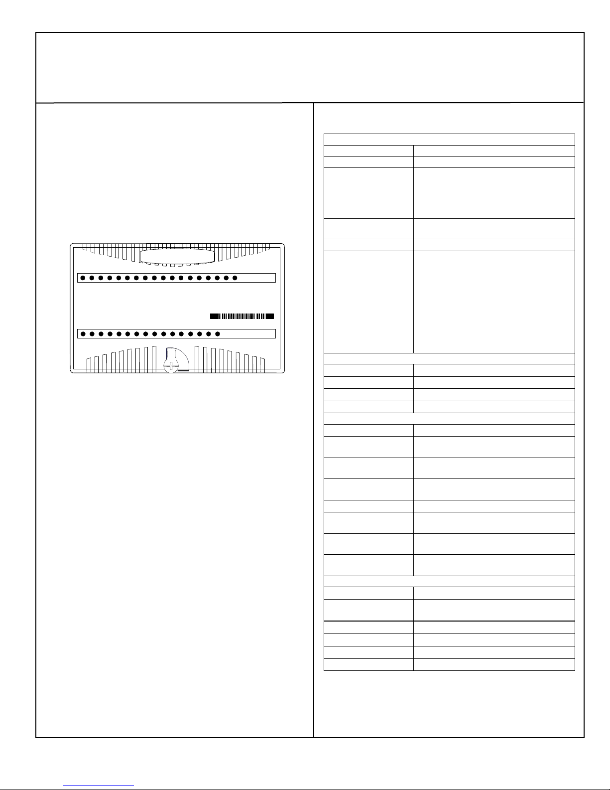
VersaMax Mixed Discrete / High-Speed Counter Module
IC200MDD841
May 2011 GFK-1561H
▪The module can perform the “pulse-train with ramp” function on
four output channels. However, no more than two should be used
simultaneously. If more than two ramps are executed at the same
time, one or more of them may terminate before the specified
number of pulses have been generated.
▪When the module’s Output Stop Mode is configured for Hold Last
State, the outputs will only respond in Stop mode if the Enable
HSC/PWM/Pulse Train Output %Q bits are still set. These bits will
remain set when the %Q memory is configured for default only
when the default value for the bits (%Q21-%Q24) is set to 1 on the
“Output Parameters” tab in the modules Hardware configuration.
Alternatively, the %Q memory can also be configured to Hold Last
State on the “Module Parameters” tab in the Hardware
Configuration.
Product Revision History
Firmware version 1.22 (upgrade kit
44A748026-G04). Resolves component
obsolescence issue. No change to
features, performance or compatibility.
Change of manufacturing location.
Updated Power Supply OK signal
circuitry.
Improvement to latching mechanism
Changed to V0 plastic for module
housing.
ATEX approval for Group 2 Category 3
applications.
Initial product release. Firmware version
1.03
Default Operation
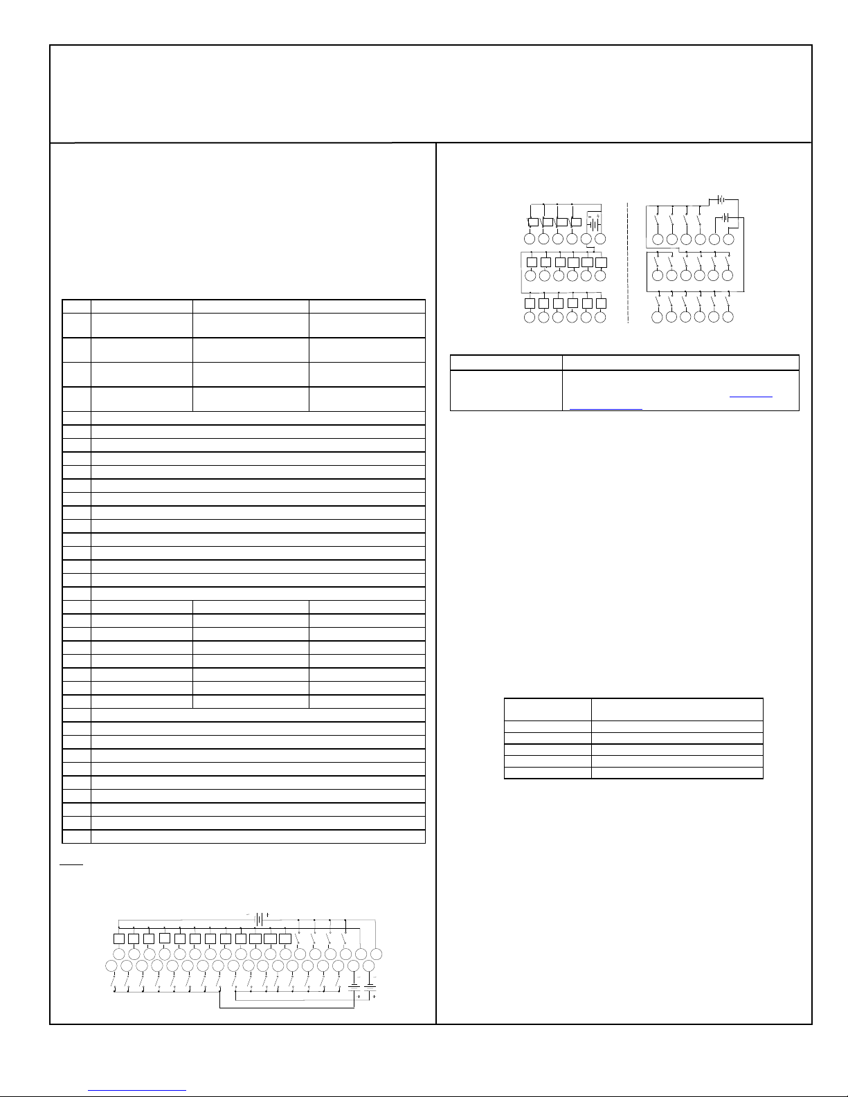
Inputs 1 - 8 are one group of high-speed counter inputs. These inputs
operate as:
▪Four Type A counters.
▪Each counter counts upward.
▪When a counter reaches its upper limit, it wraps around and starts
over.
Inputs 9 - 16 are one group of standard inputs with a common return.
Inputs 17 - 20 are one group of standard inputs with a common return.
Four of the outputs are High-speed Counter outputs. Each High-speed
Counter output is dedicated to a corresponding High-speed Counter
input.
Eight additional outputs are standard outputs.
The counter outputs use a default ON preset of +32,767, and an OFF
preset of 0. If the count reaches the ON preset, the counter’s output is
turned on. If the count reaches the OFF preset, the counter’s output is
turned OFF.
When the system is in Stop mode, the High-speed Counter outputs
continue to respond to the counter inputs and the standard outputs turn
off. The output presets continue to operate as if the CPU/NIU were
present, changing state to reflect the counter Accumulators.
In default mode, the module can temporarily change this basic operation
in response to up to four commands from the CPU or NIU. These
commands can be sent to the module in its regular output data.
▪Each counter output can be turned on or off on command.
▪Each counter can be reset to 0.
▪Each counter’s accumulator (current count) register can be loaded
with any value from -32768 to 32767.
▪Each counter’s lower and upper limits can be changed.
▪Each counter’s accumulator can be incremented by a specific
amount above its present actual value.
▪The count direction can be changed to down (or back to up).
▪The timebase for each counter’s counts-per-timebase, which
measures its rate of counting, can be changed from1000mS to any
value from 10mS to 65530mS.
▪Each counter’s preload value can be changed.
Configurable Features
The default parameters of this module can be used in many applications.
The module can be software-configured when it is installed in a PLC
system, or an I/O Station controlled by a Network Interface Unit that
supports software configuration.
The module is configured at startup. After configuration, the module
begins providing signals from the voltage or current output devices
connected to it to the CPU or NIU.
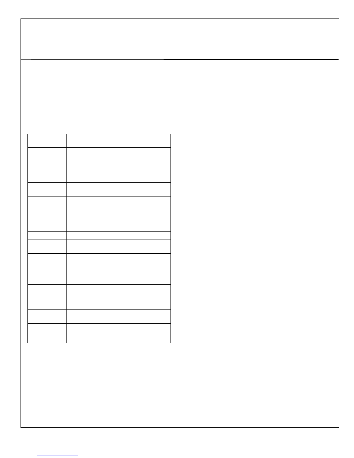
Specifies the counter configuration.
4 Type A counters,
1 Type B & 1 Type A,
1 Type B2
Defines what outputs do if the system
is in stop mode.
Normal means that HSC outputs
continue to respond to the counter
inputs and standard outputs turn off.
Preset outputs continue to operate as
if the CPU/NIU were present,
changing state to reflect the counter
Accumulators.
Force Off means all Preset outputs
are turned off and remain off until the
CPU/NIU returns to normal operation.
Hold Last means Preset outputs
retain current levels and do not reflect
the counter Accumulators.
Normal, Force All
Outputs Off, Hold
Channel #1/2/3/4
Function
Specifies channel function.
HSC, PWM, Pulse
Train, Standard,
Ramp
Counter Output
#1/2/3/4 Enable
Specifies if the counter output is
enabled. If disabled, the output is
used as a standard output.
Counter #1/2/3/4
Direction
(Type A only). Specifies whether
count inputs increment or decrement
the accumulator.
Defines whether the counter wraps if
the count limit is reached
(continuous) or if it stops at the
counter limit.