manuals.online logo
Brands
  1. Home
  2. •
  3. Brands
  4. •
  5. Versia
  6. •
  7. Floodlight
  8. •
  9. Versia LED-340B User manual

Versia LED-340B User manual

15-
Innovation, Quality, Performance
LED-340B
User Manual
Please read the instructions carefully before use
1-
TABLE OF CONTENTS
1. Safety Instructions
2. Technical Specifications
3. Installation
4. How to set the fixture
5. How to control the fixture
6. DMX 512 Configuration
7. DMX 512 Connections
8. Troubleshooting
9. Fixture Cleaning
14-
EC - Declaration of Conformity
We declare that our products (lighting equipments) comply with the following
specification and bears CE mark in accordance with the provision of the
Electromagnetic Compatibility (EMC) Directive 89/336/EEC.
EN55014-2: 1997 A1: 2001, EN61000-4-2: 1995; EN61000-4-3: 2002;
EN61000-4-4: 1995; EN61000-4-5: 1995, EN61000-4-6: 1996,
EN61000-4-11: 1994.
&
Harmonized Standard
EN60598-1: 2000+ALL: 2000+A12: 2002
Safety of household and similar electrical appliances
Part 1: General requirements
13-
9. Fixture Cleaning
The cleaning of internal must be carried out periodically to optimize light output. Cleaning
frequency depends on the environment in which the fixture operates: damp, smoky or
particularly dirty surrounding can cause greater accumulation of dirt on the fixture’s optics.
yClean with soft cloth using normal glass cleaning fluid.
yAlways dry the parts carefully.
yClean the external optics at least every 20 days. Clean the internal optics at least every
30/60 days.
2-
1.Safety Introductions
WARNING
yPlease keep this User Manual for future consultation. If you sell the fixture to another
user, be sure that they also receive this instruction booklet.
yUnpack and check carefully there is no transportation damage before using the fixture.
yIt’s important to ground the yellow/green conductor to earth in order to avoid electric
shock.
yDisconnect main power before servicing and maintenance.
yMaximum ambient temperature is Ta : 40℃. Don’t operate it where the temperature is
higher than this.
yIn the event of serious operating problem, stop using the fixture immediately. Never try
to repair the fixture by yourself. Repairs carried out by unskilled people can lead to
damage or malfunction. Please contact the nearest authorized technical assistance
center. Always use the same type spare parts.
yDo not connect the device to any dimmer pack.
yDo not touch any wire during operation and there might be a hazard of electric shock.
yTo prevent or reduce the risk of electrical shock or fire, do not expose the fixture to rain
or moisture.
yThe housing must be replaced if they are visibly damaged.
yDo not look directly at the LED light beam while the fixture is on.
yThere are no user serviceable parts inside the fixture. Do not open the housing or
attempt any repairs by yourself. In the unlikely event your fixture may require service,
please contact your nearest dealer.
yDue to the magnifying type lens, please keep the lens out of contact with direct sunlight.
Direct sunlight can cause heat to build up inside of the unit, which will seriously damage
unit.
Please read the instructions carefully which includes important
information about the installation, operation and maintenance.
For power supply, do not connect in series much more than 31 units, use
another mains supply for next 31 units.
3-
2. Technical Specifications
yFeaturing 1 x 10W tri-color high powered LED and specially designed mechanism, the
Radiant LED shoots tons of powerful and laser-like muticolor beams, covering the
entire room with amazing effects.
yGreat built-in lighting shows under Master/Slave and Sound Active
yFull range dimmer and variable strobe effects.
yOptional CA-8 easy controller for enjoying instant lighting shows at you fingertips
yLED display for easy navigation
yIdear for discotheques, clubs, bars, parties, Mobile DJs, ect.
yInput Voltage: 100V~240V 50/60Hz
yPower consumption: 20W
yFuse: T 6.3A
yLED: 1 x 10W Tri-color LEDs 30000hrs rated
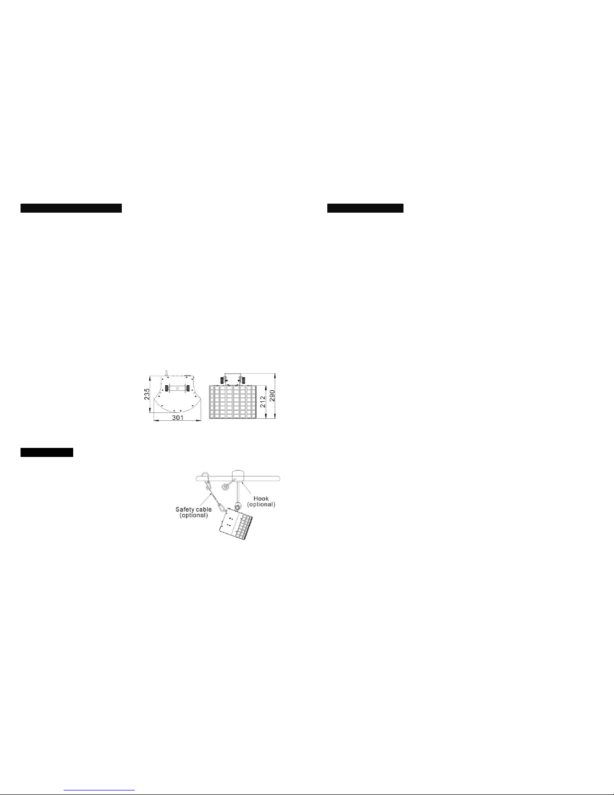
yDimension: 301 x 235 x 290mm
yWeight: 4.5kgs
3. Installation
The unit should be mounted via its screw holes
on the bracket. Always ensure that the unit is firmly
fixed to avoid vibration and slipping while operating.
Always ensure that the structure to which you are
attaching the unit is secure and is able to support a
weight of 10 times of the unit’s weight. Also always
use a safety cable that can hold 12 times of the
weight of the unit when installing the fixture.
The equipment must be fixed by professionals. And it must be fixed at a place where is
out of the touch of people and has no one pass by or under it.
12-
8. Troubleshooting
Following are a few common problems that may occur during operation. Here are some
suggestions for easy troubleshooting:
A.The fixture does not work, no light
1. Check the connection of power and main fuse.
2. Measure the mains voltage on the main connector.
B. Not responding to DMX controller
1. DMX LED should be on. If not, check DMX connectors, cables to see if link properly.
2. If the DMX LED is on and no response to the channel, check the address settings and
DMX polarity.
3. If you have intermittent DMX signal problems, check the pins on connectors or on PCB
of the fixture or the previous one.
4. Try to use another DMX controller.
5. Check if the DMX cables run near or run alongside to high voltage cables that may
cause damage or interference to DMX interface circuit.
C. Some fixtures don’t respond to the easy controller
1. You may have a break in the DMX cabling.
2. Check the LED for the response of the master/ slave mode signal.
D. No response to the sound
1. Make sure the fixture does not receive DMX signal.
2. Check microphone to see if it is good by tapping the microphone.
E. One of the channels is not working well
1. The stepper motor might be damaged or the cable connected to the PCB is broken.
2. The motor’s drive IC on the PCB might be out of condition.
11-
7. DMX512 Connections
The DMX512 is widely used in intelligent lighting control, with a maximum of 512 channels.
1. Connect the fixture together in a “daisy chain” by XLR plug cable from the output of the
fixture to the input of the next fixture. The cable cannot be branched or split to a “Y”
cable. Inadequate or damaged cables, soldered joints or corroded connectors can
easily distort the signal and shut down the system
2. The DMX output and input connectors are pass-through to maintain the DMX circuit
when one of the units’ power is disconnected.
3. At last fixture, the DMX cable has to be terminated with a terminator to reduce signal
errors. Solder a 120-ohm 1/4W resistor between pin 2(DMX-) and pin 3(DMX+) into a
3-pin XLR-plug and plug it in the DMX-output of the last fixture.
4. Each lighting fixture needs to have an address set to receive the data sent by the
controller. The address number is between 0-511 (usually 0 & 1 are equal to 1).
5. 3 pin XLR connectors are more popular than 5 pins XLR.
3 pin XLR: Pin 1: GND, Pin 2: Negative signal (-), Pin 3: Positive signal (+)
5 pin XLR: Pin 1: GND, Pin 2: Negative signal (-), Pin 3: Positive signal (+),
Pin4/5: not used
4-
4. How to set the fixture
4.1 Control Panel
○
1Display: To show the various menus and the selected functions
LED:
○
2DMX On DMX input present
○
3 MASTER On Master Mode
○
4 SLAVE On Slave Mode
○
5 SOUND Flashing Sound activation
Button:
○
6MENU To select the programming functions
○
7DOWN To go backward in the selected functions
○
8UP To go forward in the selected functions
○
9ENTER To confirm the selected functions
○
10DMX output: For DMX512 link, use 3/5-pin XLR plug cable to input DMX signal
○
11 DMX input:For DMX512 link, use 3/5-pin XLR plug cable to link the next unit.
○
12Only for remote control:By connect to the 1/4’’ microphone jack to control the unit for
Stand by, Function and Mode function.
○
13Microphone:Receive music for the sound active.
○
14Safety Ring:For attached the safety cable.
○
15Mains output:Connect to supply mains power for the next unit.
○
16Mains input:Connect to supply mains power.
5-
4.2 Main Function
To select any functions, press MENU button until the required one is shown on the display.
Select the function by ENTER button and the display will blink. Use DOWN and UP button to
change the mode. Once the required mode has been selected, press ENTER button to
setup or it will automatically return to the main functions without any change after idling 10
seconds. Back to the functions without any change press MENU button. The main functions
are shown below:
DMX 512 Address Setting
Press the MENU button up to when the is shown on the display. Pressing ENTER
button and the display will blink. Use DOWN and UP button to change the DMX 512 address.
Once the address has been selected, press ENTER button to setup or automatically exit
menu mode without any change after 10 seconds. Back to the previous functions without
any change press MENU button.
Channel Mode
10-
6. DMX512 Configuration
1 & 3-CH modes:
9-
5.2. Easy Controller (by CA-8)
The easy remote control is used only in master/slave mode. By connecting
to the 1/4” microphone jack of the first unit, you will find that the remote
controller on the first unit will control all the other units for Stand by,
Function and Mode selection
5.3 DMX Controller
Using universal DMX controller to control the units, you have to set DMX address from 1 to
512 channels so that the units can receive DMX signal.
Press the MENU button up to when the is showing on the display. Pressing ENTER
button and the display will blink. Use DOWN and UP button to change the DMX512 address.
Once the address has been selected, press and keep ENTER button pressed up to when
the display stops blinking or storing automatically 8 seconds later. To go back to the
functions without any change press the MENU button again. If you use please refer to the
following diagram to address your DMX512 channel for the first 4 units.
1 channel mode:
3 channels mode:
Blackout Blackout the unit
Function 1. SynchroStrobe
2. Asynchro Strobe
3. Sound Strobe
Select Show
(Show 1-8)
Select Speed
1. Slow
2. Middle
3. Fast
Mode Sound/Strobe
(LED OFF) Show
(LED ON) LED blinking
6-
Press the MENU button up to when the is shown on the display. Pressing ENTER
button, Use DOWN and UP button to select the (1 channel) or (3
channels ) mode. Once select, press the ENTER button to setup or automatically exit menu
mode without any change after 10 seconds. To go back to the functions without any change
press the MENU button
Slave Mode
Press the MENU button up to when the is shown on the display. Pressing ENTER
button, Use DOWN and UP button to select the (master) or (slave 1) or
(Slave 2) mode. Once select, press the ENTER button to setup or automatically exit
menu mode without any change after 10 seconds. To go back to the functions without any
change press the MENU button
Show Mode
Press the MENU button up to when the is shown on the display. Pressing ENTER
button, Use DOWN and UP button to select the (Random show) or (show
1) or (Show 2) or … or (show8). Once select, press ENTER button to
store or automatically exit menu mode without any change after 10 seconds. To go back to
the functions without any change press the MENU button
Sound
Press the MENU button up to when the is shown on the display. Pressing ENTER
button, Use DOWN and UP button to select the (sound on) or (sound off).
Once select, press ENTER button to setup or automatically exit menu mode without any
change after 10 seconds. To go back to the functions without any change press the MENU
button
Blackout mode
Press the MENU button up to when the is shown on the display. Pressing ENTER
button, Use DOWN and UP button to select the (blackout) or (normal).
Once select, press ENTER button to setup or automatically exit menu mode without any
change after 10 seconds. To go back to the functions without any change press the MENU
button.
7-
LED display
Press the MENU button up to when the is shown on the display. Pressing ENTER
button and the display will blink. Use DOWN and UP button to select (display on) or
(display off) mode. Once select, press ENTER button to setup or exit menu mode
without any change after 10 seconds. Back to the functions without any change press
MENU button again.
Display Inverse
Press MENU button until is blinking on the display. Use DOWN and UP button to
select (normal) or (inverse), press ENTER button to setup. Back to the
functions without any change press MENU button.
Self-Test
Press the MENU button up to when the is blinking on the display. Pressing ENTER
button and the unit will run the built-in programmer for self-test. To go back to the functions
press the MENU button.
Fixture Hours
Press the MENU button up to when the is blinking on the display. Pressing ENTER
button and the display will show the number of working hours of the unit. To go back to the
functions press the MENU button.
Software version
Press the MENU button up to when the is blinking on the display. Pressing ENTER
button and the display will show the version of software of the unit. To go back to the
functions press the MENU button.
Reset
Press the MENU button up to when the is blinking on the display. Pressing ENTER
button and all the motors will back to their home position.
8-
4.3 Home Position Adjust
Press Enter button for about 5 seconds, “OPAN” will shown on the display, press ENTER
button to confirm, then use DOWN and UP button to adjust the home position (-127 - 127) of
the motor. Once the position has been selected, press the ENTER button to setup or exit the
offset mode without any change press the MENU button.
5. How To Control The Fixture
You can operate the unit in three ways:
1. By master/slave built-in preprogram function
2. By easy controller
3. By DMX controller
No need to turn the unit off when you change the DMX address, as new DMX address
setting will be effected at once. Every time you turn the unit on, it will show “340b” on the
display. After that the unit will be ready to receive DMX signal or run the built in programs.
5.1 Master/Slave Built In Preprogrammed Function
By linking the units in master/slave connection, the first unit will control the other units to
give an automatic, sound activated, synchronized light show. This function is good when you
want an instant show. You have to set the first unit in master mode and select
(random show), (show 1) or …or (show 8). Its DMX input jack will
have nothing plugged into it, and Its master LED will be constantly on and sound LED will
flash to the music. The other units will have to select (normal) or (2 light
show) mode, Their DMX cables plugged into the DMX input jacks (daisy chain) and the
slave led lights will constantly on.
2-light show
In slave mode, means the unit works as the master unit and means 2-light
show. In order to create a great light show, you can set on the second unit to get
contrast movement to each other, even if you have two units only.

Popular Floodlight manuals by other brands

EuroLite TS-5 user manual

EuroLite

EuroLite TS-5 user manual

Stairville LED BAR RGB owner's manual

Stairville

Stairville LED BAR RGB owner's manual

Elation ELARQUADBAR user manual

Elation

Elation ELARQUADBAR user manual

Chauvet EZpar T6 USB Quick reference guide

Chauvet

Chauvet EZpar T6 USB Quick reference guide

Philips Selecon Operation manual

Philips

Philips Selecon Operation manual

Lexing LX-LD-102P118-12 instructions

Lexing

Lexing LX-LD-102P118-12 instructions

ESYLUX EST 10-13 manual

ESYLUX

ESYLUX EST 10-13 manual

Robe CityFlex 48 user manual

Robe

Robe CityFlex 48 user manual

Show Tec StageBeam 300/500W PC manual

Show Tec

Show Tec StageBeam 300/500W PC manual

Ledj Slimline 36 RGBW user manual

Ledj

Ledj Slimline 36 RGBW user manual

Ibiza LEDFLOOD-10WH-MD user manual

Ibiza

Ibiza LEDFLOOD-10WH-MD user manual

luceco EFLD10B40-06 Installation & operating instructions

luceco

luceco EFLD10B40-06 Installation & operating instructions

Lumineux Carsington Plus Sports quick start guide

Lumineux

Lumineux Carsington Plus Sports quick start guide

Somogyi Elektronic Home PLL 800 instruction manual

Somogyi Elektronic

Somogyi Elektronic Home PLL 800 instruction manual

JB Systems LED Diamond Operation manual

JB Systems

JB Systems LED Diamond Operation manual

Eterna POLY10PIR installation instructions

Eterna

Eterna POLY10PIR installation instructions

thomann STAIRVILLE LED Bar 120/4 RGB DMX user manual

thomann

thomann STAIRVILLE LED Bar 120/4 RGB DMX user manual

Robus RHL1030-04 manual

Robus

Robus RHL1030-04 manual

manuals.online logo
manuals.online logoBrands
  • About & Mission
  • Contact us
  • Privacy Policy
  • Terms and Conditions

Copyright 2025 Manuals.Online. All Rights Reserved.