1
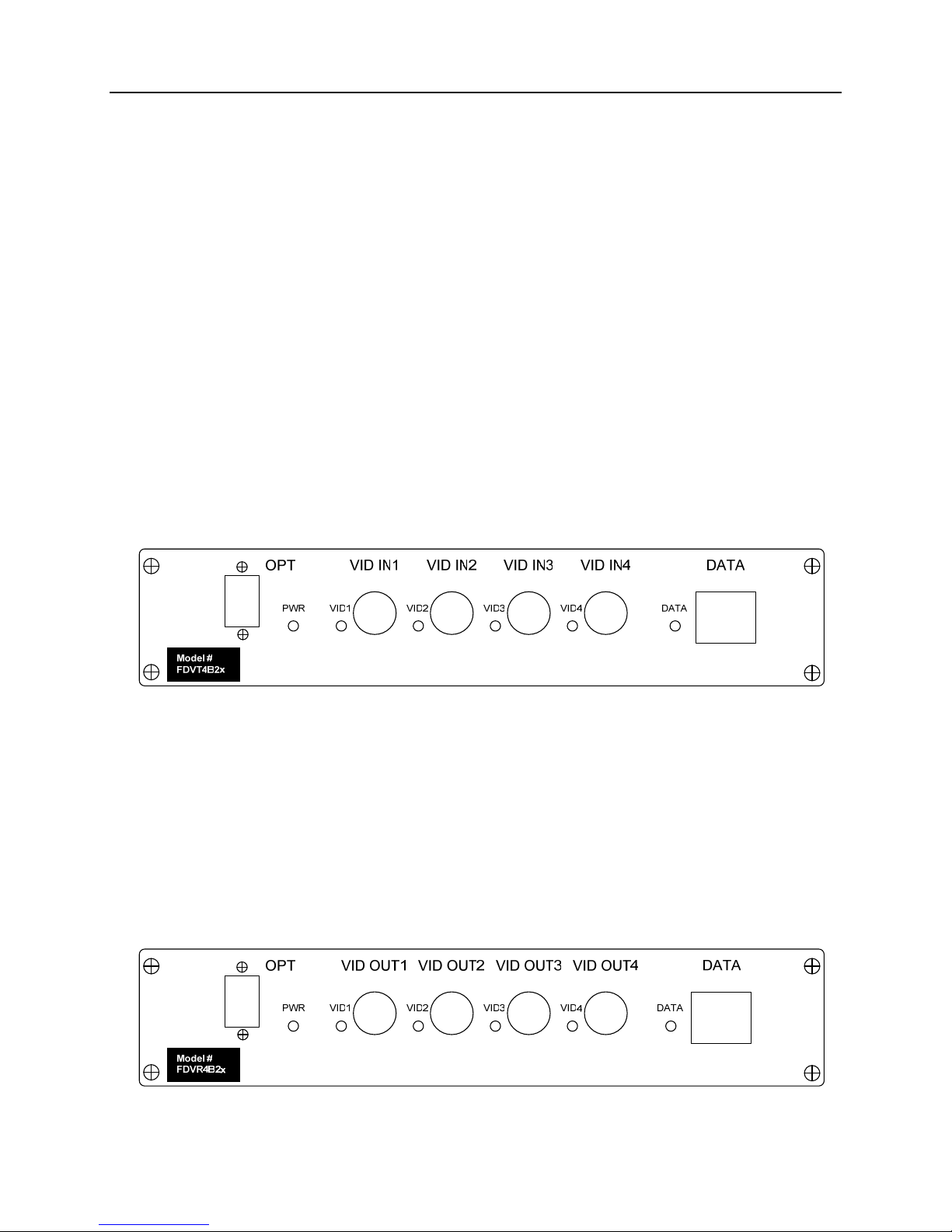
www.versitron.com FVxM4B2x
PROPRIETARY DATA
All data in this manual is proprietary and may not be disclosed,
used or duplicated, for procurement or manufacturing purposes,
without prior written permission by VERSITRON.
VERSITRON LIFETIME WARRANTY
All VERSITRON products are covered by a Lifetime Warranty against defects in materials and
workmanship. This coverage is applicable to the original purchaser and is not transferable.
We repair, or at our option, replace parts/products that, during normal usage and operation, are
proven to be defective during the time you own the products, provided that said products and
parts are still manufactured and/or available. Such repair/replacement is subsequent to receipt
of your product at our facility and our diagnostic evaluation and review of the unit.
This warranty does not cover damage to products caused by misuse, mishandling, power surges,
accident, improper installation, neglect, alteration, improper maintenance, or other causes which
are not normal and customary applications of the products and for which they were not intended.
No other warranty is expressed or implied, and VERSITRON is not liable for direct, indirect,
incidental or consequential damages or losses.
In the unlikely event a warranty issue should arise, simply contact us at 302-894-0699 or
1-800-537-2296 or via email at fiberlink@versitron.com to obtain a Return Material
Authorization (RMA) number, along with instructions for returning your product.