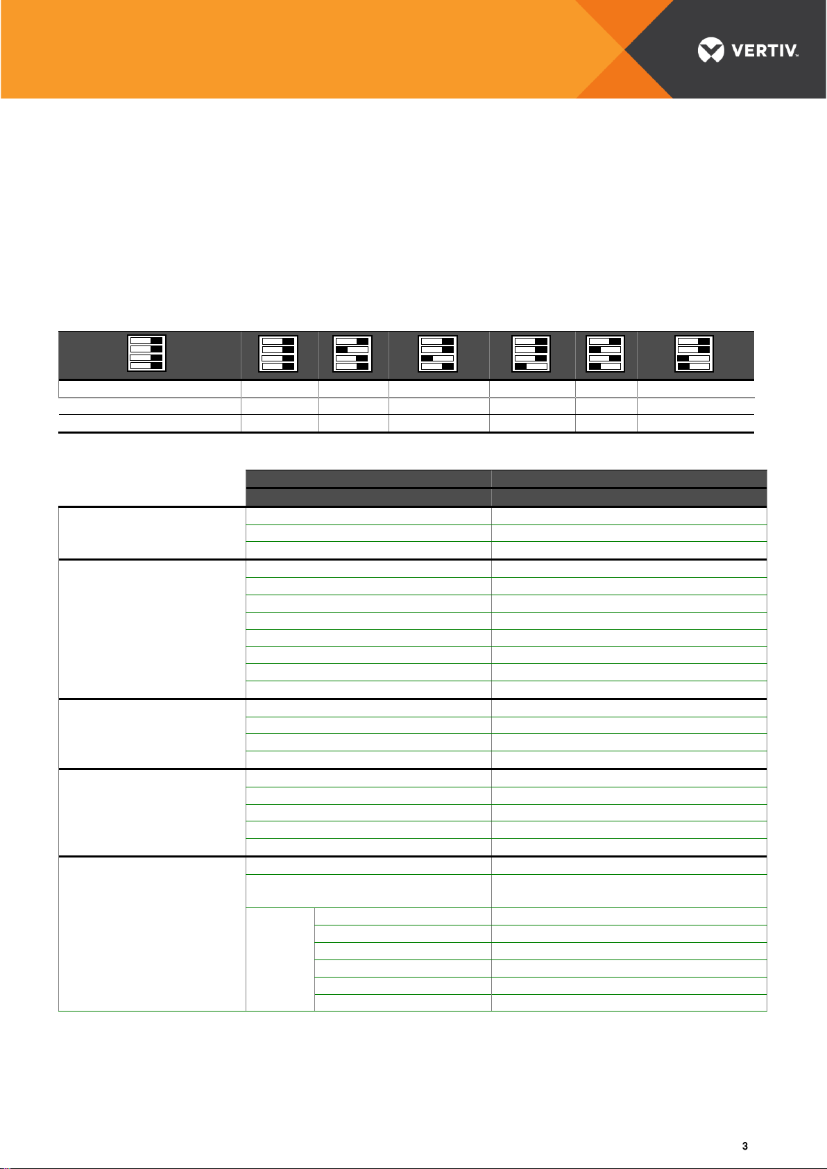
Vertiv CE-P 2.5A 30/48 User manual

CE-P 2.5 30/48
Battery charger / Power Supply
©2017 Vertiv Co. All rights reserved | CE-P 2.5 30/48 | 6011154 | Notice utilisation | v06 | 05.17
Installation and User Guide
The CE-P is dual-voltage, and is designed to charge 30 volt or 48 volt batteries having a maximum capacity of
40 Ah or to maintain the charge of batteries having greater capacity. With numerous protections and advanced
functions, it guarantees reliable operation and extended life for your batteries.
It can also be configured in a power supply mode, with an adjustable output voltage.
1 INSTALLATION AND CONNECTION
155 mm
65 mm
Unclip to open
Do not open with open on!
CE-P
EC3
EC2
EC1
EC4
Respect the
installation direction!
Mounting
possibilities
LED
2 x M5
Center-to-center
distance
95 mm
4 x M4
Center-to-
center
distance
95 x 90 mm
or
or
Omega rail
SWITCH
1,2,3,4
F2
ADJUST
FS
112 mm
106 mm
For the specific output voltage settings, indicate the value
in the “SETTINGS” box
Connectors EC1 to EC4 are unpluggable
Capacity of connection terminals: 2.5 mm²
Minimum connection wire size of N-L-PE and+/- terminals: 1.5 mm²
Other terminals: min 0.8 mm²
Check the configuration before turning on power!

CE-P 2.5 30/48
Battery charger / Power Supply
©2017 Vertiv Co. All rights reserved | CE-P 2.5 30/48 | 6011154 | Notice utilisation | v06 | 05.17
2 START UP
The CE-P can be set either for an output of 30V or 48V. To select the output voltage, make sure the power is
off, open cover and place switch 1 into the desired position.
▪Power Supply mode
To use CE-P as a power supply, power off and place switch 2 in the “adjust” position. When power is on, the
output can be adjusted between 30 and 40 volts for the 30V setting, and between 48 and 60 volts for the 48V
setting using “adjust” potentiometer. The setting can be written on the cover sticker as a reminder.
▪Battery charger mode
Settings are pre-defined for Lead Acid Batteries. To use these settings, power off, set switch 2 into "auto"
position and select the desired charging level with switch 3. The "2.275 V/CELL" position corresponds to
sealed, maintenance-free batteries (PbSe). The "2.23 V/CELL" shall be used for flooded lead-acid batteries
(PbO).
If the desired charging voltage is different from these values, or if a NiCd battery is used, the output voltage
can be adjusted. Turn off the power, set switch 2 to “adjust”. Turn power on and set using the “adjust”
potentiometer. The setting can be printed on the label. Note: For Nickel-Cadmium (NiCd) batteries, the usual
charging voltage is 1.42 V per cells.
CAUTION!
Before powering the unit:
▪Respect mounting orientation of the product: vertically, connectors at the bottom.
▪Verify that the vents are not obstructed. 50 mm required above and below unit.
▪Check that the rated voltage corresponds to the application.
▪If a specific output voltage is required, check the value on the sticker.
▪Make sure cover is securely closed
▪Before connecting the battery, verify polarity.
3 ADVANCED FUNCTIONS
▪FAULT report
CE-P features numerous protections to protect itself as well as the connected equipment. The faults
selected by switch 4 (position D: all defects are reported, mM position: thresholds of Max. and Min. faults are
reported) on a NO + NC dry contact (connector EC3), on standby or faulted. The blinking of the LED
indicates the type of alarm.
Battery low level: (fault stored in memory) 2-second threshold delay, set at 26 V for the 30 V position and
42 V for the 48 V position. LED blinks rapidly to indicate the alarm.
Charger High voltage: (fault stored in memory) protects the load in case of regulation loss by stopping the
charger. 5 second threshold delay, set at 42 V for the 30 V position and 62 V for the 48 V position. LED
blinks rapidly to indicate the alarm: disconnect mains and battery for 10 seconds to reset.
Mains off or mains fuse FS blown: (fault not stored in memory) the LED goes out
Battery fault following the test: (fault stored in memory) remove the strap between the “TEST” terminals of
connector EC4 to clear the fault. (See § Battery Test).
Note: in case of current limitation (output overload or deeply discharged battery) the LED intermittently blinks but no
remote alarm is signaled.
▪BOOST function
To charge the batteries, it may be useful to use the BOOST function to increase the charging voltage for a
few hours. The CE-P features a BOOST function that raises the charging voltage by 3.8 % (PbSE) or by 5.4
% (PbO), limited to 2.5 V per cell.
This function is activated by connecting the “BOOST” terminals of connector EC4 for 2 seconds. The
terminal connecting cable shall not to exceed 2 meters. This mode lasts 12 hours. The mode can be
interrupted before the end of the 12-hour period by removing the EC4 connector for 2 seconds from the
“BOOST” terminals.

CE-P 2.5 30/48
Battery charger / Power Supply
©2017 Vertiv Co. All rights reserved | CE-P 2.5 30/48 | 6011154 | Notice utilisation | v06 | 05.17
▪Battery TEST
In order to ensure that the battery is capable of feeding the load, the CE-P features a built-in TEST function
that reduces the voltage to 30 volts when in 30 V position and to 48 volts when in 48 V position.
This function is activated by connecting the “TEST” terminals of connector EC4. The terminal connecting
cable shall not to exceed 2 meters.
After 30 seconds, the CE-P indicates the end of the test by a LED blink. If the battery is defective, meaning
that the voltage has dropped to 2 V / cell, the LED continues to blink fast and the remote alarm signals that
the battery must be replaced. Normal mode returns as soon as the strap between the “TEST” terminals is
removed.
4 DATA SHEET
OUTPUT VOLTAGE
34.125 V
33.45 V
30 à 40 V
54.6 V
53.6 V
48 à 60 V
Strap between "TEST"
30 V
30 V
30 V
48 V
48 V
48 V
Strap between "BOOST"
35.4 V
34.72 V
Value + 3,8%
56.7 V
56.5 V
Value + 3,8%
CARACTERISTICS
PRODUCT
CE-P 2.5A 30/48
Reference
6011062
INPUT
Mains voltages
208, 220, 230 and 277 Vac
Input voltage / frequency limits
187 Vac → 305 Vac, 47 Hz → 63 Hz
Input fuse FS
2A Time delay
OUTPUT
Output fuse F2
5 A Time delay
Output current limiting
2.5A ± 5 %
Dwell time on mains outage
10 ms
Output voltage tolerance
± 1%
Switching frequency
70 kHz
Ripple voltage peek to peek (< 30MHz)
< 500 mV
RMS ripple voltage
< 0.2%
Capacity of the FAULT relay
250 Vac / 1 A
MISCELLANEOUS
Efficiency
85%
Dielectric strength Input / Output
4200 Vdc / 1 min
Dielectric strength Input / PE
2800 Vdc / 1 min
Dielectric strength Output / PE
800 Vdc / 1 min
ENVIRONMENT
Weight
0.5 kg
Protection index
IP 20
Operating / storage temperature
-20 °C to +50 °C / -45 °C to +85 °C
Cooling
Natural convection
Relative Humidity
< 95 % at 20 °C
STANDARDS
Charger / Power Supply
NF C 58-311 / EN 61204
DBT
NF EN60950-1 §2.10, §5.2, Safety LV
compliant
EMC
NF EN 55011 and 55022
NF EN 61000- 3-2
NF EN 61000- 4-2
NF EN 61000- 4-3, 4-4, 4-6
NF EN 61000- 4-5
NF EN 61000- 6-2, 6-4
D
2.275 V/Cell
Auto
30V
mM
2.23 V/Cell
Adjust
48V

CE-P 2.5 30/48
Battery charger / Power Supply
VertivCo.com
30 avenue Montgolfier –BP90
69684 Chassieu
France
Tel: +33 (0)4 72 47 63 77
Notice : 6011154
Révision : 06
Version : UK
Date : 02/05/17
Visa : ELA
© 2017 Vertiv Co. All rights reserved. Vertiv, the Vertiv logo and Chloride are trademarks or registered trademarks of Vertiv Co. All other names and logos
referred to are trade names, trademarks or registered trademarks of their respective owners. While every precaution has been taken to ensure accuracy and
completeness herein, Vertiv Co. assumes no responsibility, and disclaims all liability, for damages resulting from use of this information or for any errors or
omissions. Specifications are subject to change without notice.
5 TROUBLE SHOOTING
If the problem remains, call VERTIV maintenance services at +33 472 47 63 80.
6 PRODUCT FAMILY
Vertiv Industrial Systems SAS design and manufacture a wide range of battery chargers and power supply
for numerous applications. Visit our web sites, www.vertivco.com, for more information about these products.
Do not hesitate to consult our sales representatives to determine the equipment best adapted for your
needs.
This is a short abstract of our range of products :
Single output
▪CE-P : from 2.5 to 8 amps at 12 volts, 5 amps at 24 volts, and 2.5 amps at 30 and 48 volts
▪DELTA : 10 or 20 amps at 12 volts, 10 or 20 amps at 24 volts and 5 or 10 amps at 48 volts
Dual output (battery and load)
▪Alpha : 900 w and 1800 w at 24 volts, 48 volts, 110 volts, 125 volts and 220 volts
Various optionsare available such as display, remote alarms, batteries, metal housing…
Led
Remot
e
4-5-6
Status
Possible causes
Solution
On
Mains on,
normal operation
Intermittent
Unit in current limitation
or boost mode
Battery deeply discharged
or overcharged
or boost mode
Charging the battery may take few hours.
If necessary, disconnect the battery, verify
output voltage and connected load.
Off
No output voltage
Mains off
Check mains and upstream protections
Fuse FS blown
Replace fuse FS
Overvoltage protection
Disconnect the battery for 30 seconds
Blinking
Incorrect output voltage
Charger high voltage or
Battery low voltage
CE-P not adapted to the load
Replace the charger
Blinking
during battery TEST
Battery fully discharged or
defective
Recharge the battery for 24 hours. If problem
remains, replace the battery.
Off
Battery is not charging
Fuse F2 blown
Verify battery connections (+ and -)
Replace fuse F2
Table of contents
Other Vertiv Batteries Charger manuals