VESTEL EVC04 Series Instruction sheet

ELECTRIC VEHICLE CHARGER
EVC04 Series
Installation Guideline
Ghid de instalare

English - PB English - 1© 2021 Vestel - All rights reservedIG v7.3.1 11.2021
Contents
1 - SAFETY INFORMATION...................................................................................................................3
1.1 - SAFETY WARNINGS....................................................................................................3
1.2 - GROUND CONNECTION WARNINGS...........................................................................4
1.3 - POWER CABLES, PLUGS and CHARGING CABLE WARNINGS.....................................4
1.4 - WALL MOUNTING WARNINGS........................................................................................4
2 - DESCRIPTION...................................................................................................................................5
2.1 - MODEL DESCRIPTION.................................................................................................5
2.2 - MODEL REFERENCES................................................................................................6
3 - GENERAL INFORMATION..............................................................................................................7
3.1 - INTRODUCTION OF THE PRODUCT COMPONENTS..................................................7
3.1.1 - RCD MODELS............................................................................................7
3.1.2 - MID MODELS..........................................................................................8
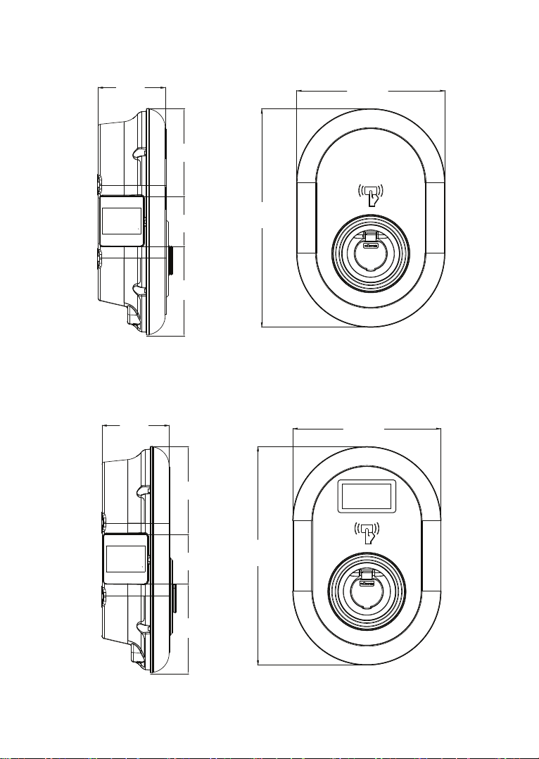
3.2 - DIMENSIONAL DRAWINGS.........................................................................................9
3.2.1 - Without Display Model............................................................................9
3.2.2 - With Display Model................................................................................9
4 - REQUIRED EQUIPMENT, TOOLS and ACCESSORIES..................................................................10
5 - TECHNICAL SPECIFICATION........................................................................................................11
6 - INSTALLING CHARGING STATION................................................................................................13
6.1 - BOX CONTENTS FOR CHARGING STATION WITH SOCKET AND CABLE..................13
6.2 - SUPPLIED INSTALLATION EQUIPMENT and ACCESSORIES....................................13
6.3 - PRODUCT INSTALLATION STEPS..............................................................................15
6.3.1 - OPENING THE COVER OF THE CHARGING STATION...........................15
6.3.2 - WALL MOUNT INSTALLATION................................................................16
6.3.3 - SINGLE PHASE CHARGING STATION AC MAINS CONNECTION............19
6.3.4 - THREE PHASE CHARGING STATION AC MAINS CONNECTION..............21
6.3.5 - ADJUSTING CURRENT LIMITER..............................................................23
6.3.6 - DIP SWITCH SETTINGS..........................................................................24
6.3.6.1 - DATA CABLE CONNECTION..............................................25
6.3.6.2 - EXTERNAL ENABLE INPUT FUNCTIONALITY...................26
6.3.6.3 - LOCKED CABLE FUNCTION (Model with Socket)................28
6.3.6.4 - POWER OPTIMIZER (REQUIRES OPTIONAL
ACCESSORIES)................................................................29
6.3.7 - MODE SELECTION SWITCH SETTINGS................................................32
6.3.8 - LOAD SHEDDING...................................................................................33
6.3.9 - MONITORING OF WELDED RELAY CONTACTS FAILURE......................34
6.3.10 - FACTORY RESET....................................................................................35
6.3.11 - RESETTING LOCAL RFID CARD LIST AND REGISTERING NEW MASTER

English - 2© 2021 Vestel - All rights reservedIG v7.3.1 11.2021
RFID CARD IN STANDALONE USAGE MODE......................................35
6.3.12 - SETTING ETHERNET PORT OF CHARGER TO STATIC IP IN STANDALONE
USAGE MODE......................................................................................36
6.3.13 - WEB CONFIGURATION INTERFACE ENABLE / DISABLE..................36
6.4 - OCPP CONNECTION...................................................................................................37
6.4.1 - CONNECT OCPP OVER CELLULAR NETWORK (Optional)....................37
6.4.2 - CONNECT OCPP OVER ETHERNET.......................................................37
6.5 - COMMISSIONING........................................................................................................39
6.5.1 - CONNECT PC TO THE SAME NETWORK WITH SMART BOARD.............40
6.5.2 - OPENING WEB CONFIGURATION INTERFACE WITH BROWSER...........40
6.5.3 - OPENING WEB CONFIGURATION INTERFACE VIA WIFI HOTSPOT.........42
6.6 - WEB CONFIGURATION INTERFACE...........................................................................43
6.6.1 - MAIN PAGE...........................................................................................43
6.6.2 - CHANGE GENERAL SETTINGS OF THE DEVICE...................................43
6.6.2.1 - Display Language.............................................................43
6.6.2.2 -Display Backlight Settings..................................................43
6.6.2.3 -Led Dimming Settings.......................................................44
6.6.2.4 -Display Theme....................................................................45
6.6.2.5 -Display Service Contact Info..............................................45
6.6.2.6 -Logo Settings......................................................................46
6.6.3 - INSTALLATION SETTINGS....................................................................46
6.6.3.1 - Earting system..................................................................46
6.6.3.2 - Current Limiter Settings..................................................46
6.6.3.3 - Unbalanced Load Detection.............................................47
6.6.3.4 - External Enabled Input....................................................48
6.6.3.5 - Lockable Cable...................................................................48
6.6.3.6 - Power Optimizer Total Current Limit.................................49
6.6.4 - CHANGE OCPP SETTINGS OF THE DEVICE..........................................49
6.6.5 - CHANGE NETWORK INTERFACES SETTINGS OF THE DEVICE..............51
6.6.6 - CHANGE STANDALONE MODE SETTINGS OF THE DEVICE...................53
6.6.7 - MAKING SYSTEM MAINTANENCE OF THE DEVICE..............................54
6.6.8 - FIRMWARE UPDATE SCREEN FLOW (With Display Models)...............56
6.6.9 - CHANGE STANDALONE MODE SETTINGS OF THE DEVICE.................57

English - 2 English - 3© 2021 Vestel - All rights reservedIG v7.3.1 11.2021
1 - SAFETY INFORMATION
CAUTION
RISK OF ELECTRIC SHOCK:
CAUTION: ELECTRIC VEHICLE CHARGER DEVICE SHALL BE MOUNTED BY A LICENSED OR AN EXPERI-
ENCED ELECTRICIAN AS PER ANY REGIONAL OR NATIONAL ELECTRIC REGULATIONS AND STANDARDS
IN EFFECT.
CAUTION
AC grid connection and load planning of the electric vehicle charging device
shall be reviewed and approved by authorities as specified by the regional
or national electric regulations and standards in effect. For multiple electric
vehicle charger installations the load plan shall be established accordingly. The manufacturer shall
not be held liable directly or indirectly for any reason whatsoever in the event of damages and risks
that are borne of errors due to AC grid supply connection or load planning.
IMPORTANT - Please read these instructions fully before installing or operating
1.1 - SAFETY WARNINGS
• Keep this manual in a safe place. These safety and operating instructions must be kept in a
safe place for future reference.
• Check that the voltage marked on the rating label and do not use charging station without
appropriate mains voltage.
• Do not continue to operate the unit if you are in any doubt about it working normally, or if it is
damaged in any way - switch off the mains supply circuit breakers (MCB and RCCB). Consult
your local dealer.
• The ambient temperature range should be between –35 °C and +55 °C without direct sunlight
and at a relative humidity of between 5 % and 95 %. Use the charging station only within these
specified operating condition.
• The device location should be selected to avoid excessive heating of the charging station. High
operating temperature caused by direct sunlight or heating sources, may cause reduction of
charging current or temporary interruption of charging process.
• The charging station is intended for outdoor and indoor use. It can also be used in public places.
• To reduce the risk of fire, electric shock or product damage, do not expose this unit to severe
rain, snow, electrical storm or other severe weathers. Moreover, the charging station shall
not be exposed to spilled or splashed liquids.
• Do not touch end terminals, electric vehicle connector and other hazardous live parts of the
charging station with sharp metallic objects.
• Avoid exposure to heat sources and place the unit away from flammable, explosive, harsh, or
combustible materials, chemicals, or vapors.
• Risk of Explosion. This equipment has internal arcing or sparking parts which should not be
exposed to flammable vapors. It should not be located in a recessed area or below floor level.
• This device is intended only for charging vehicles not requiring ventilation during charging.

English - 4© 2021 Vestel - All rights reservedIG v7.3.1 11.2021
• To prevent risk of explosion and electric shock, ensure that the specified Circuit Breaker and
RCD are connected to building grid.
• The lowest part of the socket-outlet shall be located at a height between 0,5 m and 1,5 m
above ground level.
• Adaptors or conversion adapters are not allowed to be used. Cable extension sets are not
allowed to be used.
WARNING: Never let people (including children) with reduced physical, sensory or men-
tal capabilities or lack of experience and or knowledge use electrical devices unsupervised.
CAUTION: This vehicle charger unit is intended only for charging electric vehicles not
requiring ventilation during charging.
1.2 - GROUND CONNECTION WARNINGS
• Charging station must be connected to a centrally grounded system. The ground conductor
entering the charging station must be connected to the equipment grounding lug inside the
charger. This should be run with circuit conductors and connected to the equipment grounding
bar or lead on the charging station. Connections to the charging station are the responsibility
of the installer and purchaser.
• To reduce the risk of electrical shock, connect only to properly grounded outlets.
• WARNING : Make sure that during installing and using, the charging station is constantly
and properly grounded.
1.3 - POWER CABLES, PLUGS and CHARGING CABLE WARNINGS
• Be sure that charging cable is Type 2 socket compatible on charging station side.
• A damaged charging cable can cause fire or give you an electric shock. Do not use this product
if the flexible Charging cable or vehicle cable is frayed, has broken insulation, or shows any
other signs of damage.
• Ensure that the charge cable is well positioned thus; it will not be stepped on, tripped over,
or subjected to damage or stress.
• Do not forcefully pull the charge cable or damage it with sharp objects.
• Never touch the power cable/plug or vehicle cable with wet hands as this could cause a short
circuit or electric shock.
• To avoid a risk of fire or electric shock, do not use this device with an extension cable. If the
mains cable or vehicle cable is damaged it must be replaced by the manufacturer, its service
agent, or similarly qualified persons in order to avoid a hazard.
1.4 - WALL MOUNTING WARNINGS
• Read the instructions before mounting your charging station on the wall.
• Do not install the charging station on a ceiling or inclined wall.
• Use the specified wall mounting screws and other accessories.
• This unit is rated for indoor or outdoor installation. If this unit is mounted outdoors, the
hardware for connecting the conduits to the unit must be rated for outdoor installation and
be installed properly to maintain the proper IP rating on the unit.

English - 4 English - 5© 2021 Vestel - All rights reservedIG v7.3.1 11.2021
2 - DESCRIPTION
2.1 - MODEL DESCRIPTION
Model Name
MODEL DESCRIPTION: EVC04-AC**-*
EVC04 : Electric Vehicle AC Charger (Mechanical Cabinet 04)
1st Asterisk (*) : Rated Power
7 : 7.4 kW (1Phase Supply Equipment)
11 : 11 kW (3Phase Supply Equipment)
22 : 22 kW (3Phase Supply Equipment)
2nd Asterisk (*) can include combinations of the following communication
module options. RFID reader is standard equipment for all of the model
variants. “S” option must be included for selecting combinations of W and L:
Blank : No connectivity module except RFID reader
S : Smart Board with Ethernet Port
W : Wi-Fi module or WiFi & Bluetooth module
L : LTE / 3G / 2G module
P : ISO 15118 PLC module
3rd Asterisk (*) : Can be one of the following:
Blank : No Display
D : 4.3” TFT color display
4th Asterisk (*) can include combinations of the following:
Blank : No RCCB
A : Charging unit with Type-A RCCB
MID: Charging unit with MID Meter
5th Asterisk (*) can be one of the following:
Blank : Case-B Connection with normal socket
T2S : Case-B Connection with shuttered socket
T2P : Case-C Connection with Type-2 plug
T1P : Case-C Connection with Type-1 plug
Cabinet EVC04
Table-1

English - 6© 2021 Vestel - All rights reservedIG v7.3.1 11.2021
2.2 - MODEL REFERENCES
Model reference table does not include all model variants of EVC04.
Single
phase
Three
phase
Smart
LTE
WiFi
Display
MID Meter
Type 2
socket
Shuttered
type 2
socket
output
RCCB
Type-A
DC 6mA
RCD
Type-2
Attached
Cable
Type-1
Attached
Cable
EVC04-AC7SW x x x x x
EVC04-AC7SWA x x x x x x
EVC04-AC7SLA-T2P x x x x x x
EVC04-AC7SWDA-T2S x x x x x x x
EVC04-AC7SLWDA-T1P x x x x x x x x
EVC04-AC11SLD x x x x x x
EVC04-AC11SWDA x x x x x x x
EVC04-AC11SLWDA-T2P x x x x x x x x
EVC04-AC11SLWDA-T2S x x x x x x x x
EVC04-AC22SLDMID x x x x x x x
EVC04-AC22SWDA x x x x x x x
EVC04-AC22SWD x x x x x x
EVC04-AC22SLWDA-T2P x x x x x x x x
EVC04-AC22SLWDA-T2S x x x x x x x x
Table-2

English - 6 English - 7© 2021 Vestel - All rights reservedIG v7.3.1 11.2021
3 - GENERAL INFORMATION
3.1 - INTRODUCTION OF THE PRODUCT COMPONENTS
3.1.1 - RCD MODELS
Socket Equipped Models Tethered Cable Models
3
2
1
5
6
9
44
8
5
3
2
1
6
7
10
9 8
7
Figure.1
en Socket Models
1- Information Display (Optional)
2- RFID Card Reader
3- Status indicator LED
4- Access cover for residual
current device (Optional)
5- Socket Outlet
6- Product Label
7- Charging station
communication cable gland nut
8- Charging station
communication cable gland nut
9- Charging station supply inlet
gland nut
en Tethered Cable Models
1- Information Display (Optional)
2- RFID Card Reader
3- Status indicator LED
4- Access cover for residual
current device (Optional)
5- Dummy Socket
6- Charging Plug
7- Product Label
8- Charging cable
9- Charging station
communication cable gland nut
10- Charging station supply inlet
gland nut

English - 8© 2021 Vestel - All rights reservedIG v7.3.1 11.2021
3.1.2 - MID MODELS
3
2
1
5
6
8
4
79
en Socket Models with MID Meter
1- Information Display (Optional)
2- RFID Card Reader
3- Status indicator LED
4- MID Meter Display (Optional)
5- Socket Outlet
6- Product Label
7- Charging station communication
cable gland nut
8- Charging station supply inlet
gland nut
9- Charging station communication
cable gland nut

English - 8 English - 9© 2021 Vestel - All rights reservedIG v7.3.1 11.2021
3.2 - DIMENSIONAL DRAWINGS
3.2.1 - Without Display Model
315.0
460.0
135.0
177.5
101.0
181.0
Figure-2
3.2.2 - With Display Model
315.0
460.0
135.0
177.5
101.0
181.0
Figure-3

English - 10© 2021 Vestel - All rights reservedIG v7.3.1 11.2021
4 - REQUIRED EQUIPMENT, TOOLS and ACCESSORIES
Drill Bit 8mm Impact Drill PC
T25
Volt Indicator Torx T25 Security
Screwdriver Water Level
Flathead Screwdriver (Tip
width 2.00-2.5 mm) Pointed Spudger Right Angle Screwdriver Adapter /
Torx T20 Security Bit
RJ45 Crimping Tool Cat5e or cat6 ethernet
cable
Table-3

English - 10 English - 11© 2021 Vestel - All rights reservedIG v7.3.1 11.2021
5 - TECHNICAL SPECIFICATION
This product is compliant to IEC61851-1 (Ed3.0) standard for Mode 3 use.
Model EVC04-AC22 Series EVC04-AC11 Series EVC04-AC7 Series
IEC Protection class Class - I
Vehicle
Interface
Socket Model Socket TYPE 2 (IEC 62196)
Cable Model Cable with TYPE 2 ( IEC 62196) Female Plug
Voltage and Current Rates 400VAC 50/60 Hz -
3-phase 32A
400VAC 50/60 Hz-
3-phase 16A
230VAC 50/60 Hz -
1-phase 32A
AC Maximum Charge Output 22kW 11kW 7.4kW
Idle Power Consumption 3.5W
Built-in Residual Current
Sensing module 6mA
Required Circuit Breaker on
AC Mains 4P-40A MCB Type-C 4P-20A MCB Type-C 2P-40A MCB
Type-C
Required Leakage Current Re-
lay on AC Mains (for products
which are not equipped with
RCCB Type A)
4P -40A - 30mA RCCB
Type-A
4P -20A - 30mA RCCB
Type-A
2P -40A - 30mA
RCCB Type-A
Required AC Mains Cable 5x 6 mm² (< 50 m)
External Dimensions:
Ø 18–25 mm
5x4 mm² (< 50 m)
External Dimensions: Ø
18–25 mm
3x 6 mm² (< 50 m)
External Dimen-
sions: Ø 13-18 mm
CONNECTIVITY
Ethernet 10/100 Mbps Ethernet (Standard with Smart Options)
Wi-Fi (Optional) Wi-Fi 802.11 a/b/g/n/ac
Celullar (Optional) LTE: B1 (2100 MHz), B3 (1800 MHz), B7 (2600 MHz), B8 (900 MHz), B20
(800 MHz), B28A (700 MHz)
WCDMA: B1 (2100 MHz), B8 (900 MHz)
GSM: B3 (1800 MHz), B8 (900 MHz)
OTHER FEATURES (Connected Models)
Diagnostics Diagnostics over OCPP
WebconfigUI
Software Update Remote software update over OCPP
WebconfigUI update
Remote software update with server

English - 12© 2021 Vestel - All rights reservedIG v7.3.1 11.2021
AUTHORIZATION
RFID ISO-14443A/B and ISO-15693
MECHANICAL SPECIFICATIONS
Material Plastic
Product size 315 mm (Width) x 460 mm (Height) x 135 mm (Depth)
Dimensions (with package) 405 mm (Width) x 530 mm (Height) x 325 mm (Depth)
Product weight
5 kg for socket equipped model,
6,8kg for tethered cable model (3 Phases)
5,5kg for tethered cable model (1 Phase)
Weight with package
7,1 kg for socket equipped model,
8,9kg for tethered cable model (3 Phases)
7,6kg for tethered cable model (1 Phase)
AC Mains Cable Dimensions For three-phase models Ø 18-25 mm
For one-phase models Ø 13-18 mm
Cable Inlets AC Mains / Ethernet / Modbus
ENVIRONMENTAL TECHNICAL SPECIFICATIONS
Protection Class Ingress Protection
Impact Protection
IP54
IK10 (Optional display have IK08 protection)
Usage Conditions Temperature
Humidity
Altitude
-35 °C to 55 °C (without direct sunlight)
5% - 95% (relative humidity, no devilation)
0 - 4,000m

English - 12 English - 13© 2021 Vestel - All rights reservedIG v7.3.1 11.2021
6 - INSTALLING CHARGING STATION
6.1 - BOX CONTENTS FOR CHARGING STATION WITH SOCKET AND CABLE
Socket Equipped Models Tethered Cable Models
Figure-4
6.2 - SUPPLIED INSTALLATION EQUIPMENT and ACCESSORIES
Accessory/Material Name Use For Quantity Picture
Dowels (M8x50 Plastic
Dowels) Mounting charging station to the wall 4
Torx T25 Security Screw
(M6x75) Mounting charging station to the wall 4
Gasket for screw 6x75 IP for screws which are used for
mounting charging station to the Wall. 4
Torx T20 Security L-Wrench IP for screws which are used for
mounting charging station to the Wall. 1
Wrench Disassembling and fastening the cable
glands 1

English - 14© 2021 Vestel - All rights reservedIG v7.3.1 11.2021
RJ45 Male Connector –
Optional LAN Cable connection 1
Mounting Template Mounting the charging station to the wall 1
O-Ring Mounting the charging station to the pole 3
Screw M6X20 Mounting the charging station to the pole 3
Screw M6X30
Mounting and providing earth continuity
for the charger, that mounts to metal
surface. This screw should be mounted to
the right-down hole of charging station to
the Wall. Below this screw, there should
be rubber under it to fix the ground cable.
1
IP Rubber
Fixing the ground cable with the screw
M6x30. This rubber should be placed to
right-down Wall mount hole of charging
station, under the ground cable and screw
M6x30
1
User RFID Card (Given with
E7-W and E11-W variants) Start&Stop Charging 2
Master RFID Card (Given
with E7-W and E11-W
variants)
Adding&Removing the User RFID Cards
to Local RFID List 1
MASTER
Installation Guide Installation Manual 1 Set
ELECTRIC VEHICLE CHARGER
EVC04 Series
Installation Guideline
Instruction Book User Manual 1 Set
ELECTRIC VEHICLE CHARGER
EVC04 Series
User Manual
Table-4

English - 14 English - 15© 2021 Vestel - All rights reservedIG v7.3.1 11.2021
6.3 - PRODUCT INSTALLATION STEPS
CAUTION!
• Ensure that ground resistance of the installation less than 100ohms
• Prior to mounting your charging station on the wall, read these instructions.
• Do not mount your charging station to the ceiling or an inclined wall.
• Use the wall mounting screws and other accessories specified.
• This charging station is classified as indoor and outdoor installation compatible. If the device
is installed outside the building, the hardware that will be used to connect the cables to the
charger shall be compatible with outdoor use and the charging station shall be mounted
preserving the IP rate of the charger.
6.3.1 - OPENING THE COVER OF THE CHARGING STATION
CAUTION
RISK OF ELECTRIC SHOCK
Please power off the charging station mains supply
1 2
1- Remove the cover screws with Torx T20 security L-Wrench or
Right Angle Screwdriver Adapter using Torx T20 Security Bit.
2- Open the cover.

English - 16© 2021 Vestel - All rights reservedIG v7.3.1 11.2021
6.3.2 - WALL MOUNT INSTALLATION
Wall mount installation is common for all charging station models.
1- Open the product front cover by following the instruction.
2- Place the charging station to the Wall by using the mounting template which is given in accessory
bag and mark the drill bit holes with a pencil.
3- Drill the wall on the marked points using the impact drill (8mm drill bit).
4- Place the dowels into the holes.
5- Tighten the security scews (6x75) of the product using Torx T25 Security Screwdriver.
6- Insert the AC mains cable into the charging station from the left cable gland which below the
station. Follow the AC Mains Connection instructions on the next pages, depending on the model
of the charger. (Single/Three Phase)
7- In case you mount the charging station to conductive metal surface such as metal pole etc…,
you can make ground connection via “right-bottom” screw using ground extension cable as shown
in figure-6. To ensure the grounding, you need to change the grounding cable position from “a” to
“b” as shown in figure-6. Follow the instructions below:
i. Insert the plastic support (IP rubber which is given inside accessory pack of the unit), to the
fixing hole (Position “b”)
ii. Fix the grounding cable using M6x30 screw, which is inside the artwork pack and this screw
is also used to assemble to product to the conductive metal surface.
8- Tighten the cable glands as shown in the figure. Before closing the cover of the charging station,
follow the instructions in next sections if any function related to these sections are used.
9- To close the cover of the charging station, tighten the cover screws which you were removed
with Torx T20 Security L-Wrench or Right Angle Screwdriver Adapter using Torx T20 Security Bit.
10- Mounting the charging station on the wall is finished.
2
1
5
3
4
6
Figure-5
Before next step (7), Please check the instructions for Single Phase or
Three Phase cable connections.

English - 16 English - 17© 2021 Vestel - All rights reservedIG v7.3.1 11.2021
7
b
a
Figure-6
8
Figure-7
AC Mains
Cable
Data cable
Wrench
Wrench

English - 18© 2021 Vestel - All rights reservedIG v7.3.1 11.2021
9
9 10
Figure-8
Before closing the cover of the charging station, check next
instructions if any function related to these sections are
used.

English - 18 English - 19© 2021 Vestel - All rights reservedIG v7.3.1 11.2021
6.3.3- SINGLE PHASE CHARGING STATION AC MAINS CONNECTION
1
1
2
Figure-9
1- Insert the cables to the terminal block as shown in the image. Check the table-5 below to match
Electric Terminal number with AC Cable Color.
2- Tighten the screws on the terminal block as shown in the image with the tightening tourqe of
2.5Nm.
Electric Terminal AC Cable Color
1 AC L1 (Brown)
2 AC Neutral (Blue)
3 Earth (Green-Yellow)
Table-5
Other manuals for EVC04 Series
8
This manual suits for next models
17
Table of contents
Languages:
Other VESTEL Batteries Charger manuals

VESTEL
VESTEL EVC02-AC22 Series User manual

VESTEL
VESTEL EVC04 Series User manual

VESTEL
VESTEL EVC04 Series Instruction sheet

VESTEL
VESTEL EVC04 Series User manual

VESTEL
VESTEL EVC04-AC7 User manual

VESTEL
VESTEL EVC04 Series User manual

VESTEL
VESTEL EVC04-AC Series User manual

VESTEL
VESTEL EVC03 Series User manual

VESTEL
VESTEL EVC04 Series User manual

VESTEL
VESTEL EVC03 Series Instruction sheet