Vertiv Liebert GXT RT Series User manual

Liebert® GXT RT+ 1-3 kVA, 127 V
Quick Installation Guide
SL-70692BR_REVA_10-20 1
IMPORTANT: Before installing,
connecting to supply or operating your
Liebert®GXT RT+ UPS, please review
the Safety and Regulatory Statements
sheet. For detailed installation, operating,
maintenance and troubleshooting
information refer to the GXT RT+ User
Guide for your model available at www.
Vertiv.com.
Installation
1. Inspecting the UPS
Inspect the UPS for any signs of
obvious damage. If damage is visible, do
not proceed and calll your Vertiv
represenatative.
Thank you for your recent purchase of a Vertiv UPS! We appreciate your business and
are confident that your new product will provide many years of uninterruptible power to
your connected equipment. With this purchase, you may also want to consider Vertiv’s
complete line-up of Racks, PDUs, Thermal Solutions, KVM Switches, and Serial Con-
soles. Vertiv also oers a broad array of Services and Extended Warranties. If you re-
quire any support, please don’t hesitate to reach out to Vertiv or one of our Resellers or
Local Rep Firms. We stand ready to support you. We sincerely hope that you’ll continue
to select Vertiv for all of your future infrastructure needs!
The Vertiv Team
GXTRT-1000LVRT2UXLB GXTRT-1500LVRT2UXLB
GXTRT-3000LVRT2UXLBGXTRT-2000LVRT2UXLB
Available Models
#Description
1AC Input
2Input circuit breaker
3USB communication port
4RS-232 communication port
5SNMP intelligent slot (optional)
6External battery connection
7Output receptacles

To contact Vertiv Technical Support: visit www.Vertiv.com
© 2020 Vertiv Group Corp. All rights reserved. Vertiv and the Vertiv logo are trademarks or registered trademarks of Vertiv Group Corp. All other names and logos referred to are trade names, trademarks or
registered trademarks of their respective owners. While every precaution has been taken to ensure accuracy and completeness herein, Vertiv Group Corp. assumes no responsibility, and disclaims all liability, for
damages resulting from use of this information or for any errors or omissions. Specifcations are subject to change without notice.
Liebert GXT RT+
Quick Installation Guide
2 SL-70692BR_REVA_10-20
connect one end of the external
battery cable to the second
connector on the battery
cabinet, then connect the other
end to the next battery cabinet.
• Verify that the EBC breaker is in
the “On” position.
2. Connecting AC Input
The UPS contains an attached input
cord with NEMA plug. Perform all wiring
in accordance to all local and national
electrical codes.
The UPS is equipped with output
receptacles. Connect the
equipment to be protected to the
output receptacles.
NOTE: Allow the batteries to
charge at-least 5 hours before first
start-up to ensure adequate
back-up time. The batteries charge
when the UPS is connected to AC input
regardless of the o/on status of the
UPS.
2. Choosing a location
Install the UPS in a temperature
controlled environment that is free
of corrosive and conductive
contaminants. Avoid locations near
heat or water sources and exposed
to direct sunlight.
For proper ventilation, leave 100
mm clearance on all sides of the UPS.
The input outlet should be nearby and
easily accessible.
3. Installing the UPS
The UPS and optional External
Battery Cabinets may be installed
in either a tower or rack
configuration.
• For tower installation, assemble
and attach the tower support
stands and spacers.
• For rack installation:
1. Attach the handles to the UPS.
2. Install the rail kit in the rack.
NOTE: Align shelf of rack kit with
rack U number for proper
alignment.
3. Install the UPS in the rack.
4. Secure the handles to the rack.
After UPS installation, install internal
batteries shipped in separate box.
Connections
1. Connecting External Battery
Cabinet (Optional)
External Battery Cabinets (EBC)
provide longer battery run-time for
connected devices. Refer to GXT
RT+ User Guide to select the
appropriate model and quantity for
your GXT RT+ model and
applications.
• Verify that the EBC breaker is in
the “O” position.
• Connect one end of the
supplied EBC cable to the UPS
and one end to the battery
cabinet. If connecting more
than one external battery,
Powering the UPS
NOTE: Do not start the UPS until the
installation is finished, the system is
commissioned by an authorized
engineer, and the external input circuit
breakers are closed.
1. Make sure the breaker supplying
power to the UPS is closed, and close
the input breaker on the rear of the UPS.
2. If necessary, use the LCD display to
make any required settings. (Refer to the
User Guide for configuration set up.)
3. Close all output breakers on the rear
of the UPS (or in an external panel
board, if used).
4. If external battery cabinets are
included, close the breakers on the rear
of each cabinet.
5. Power-on the UPS using the Operation
and Display Panel by pressing and
holding the power button.
NOTE: During operation, the UPS may
sound an alarm as the output
receptacles are powered. You may
press the power/mute button for 5
seconds to silence the audible alarm..
Operation and Display Panel
WIRING
Model Recommended External Breaker
GXTRT-1000LVRT2UXLB 15 A
GXTRT-1500LVRT2UXLB 15 A
GXTRT-2000LVRT2UXLB 20 A
GXTRT-3000LVRT2UXLB 30 A

Liebert® GXT RT+ 1-3 kVA, 127 V
Guia de Instalação Rápida
SL-70692BR_REVA_10-20 1
IMPORTANTE: antes de instalar,
conectar à fonte de alimentação ou
operar o UPS Liebert®GXT RT+, consulte
a folha Declarações de Segurança
e Regulamentares. Para obter informações
detalhadas de instalação, operação,
manutenção e solução de problemas,
consulte o Guia do Usuário do GXT RT+
referente ao seu modelo, disponível em
www.Vertiv.com.
Instalação
1. Inspeção do UPS
Inspecione o UPS para verificar se há
algum sinal de dano evidente. Se houver
danos visíveis, não prossiga. Ligue para
seu representante da Vertiv.
Obrigado pela sua recente aquisição do UPS Vertiv! Agradecemos por fazer negócios
conosco e temos certeza de que seu novo produto proporcionará vários anos de
alimentação ininterrupta ao equipamento conectado. Com essa compra, pode ser que
você também queira considerar a série completa de racks, PDUs, soluções térmicas,
switches KVM e consoles seriais da Vertiv. A Vertiv também oferece uma ampla gama
de serviços e garantias estendidas. Se precisar de suporte, não hesite em contatar
aVertiv, nossos revendedores ou empresas representantes locais. Estamos prontos
para ajudar você. Esperamos que continue escolhendo a Vertiv para atender a suas
futuras necessidades de infraestrutura!
Equipe da Vertiv
GXTRT-1000LVRT2UXLB GXTRT-1500LVRT2UXLB
GXTRT-3000LVRT2UXLBGXTRT-2000LVRT2UXLB
Modelos disponíveis
Nº Descrição
1Entrada CA
2Disjuntor de entrada
3Porta de comunicação USB
4Porta de comunicação RS-232
5Slot SNMP inteligente (opcional)
6Conexão de bateria externa
7Receptáculos de saída

Para entrar em contato com o suporte técnico da Vertiv, visite www.Vertiv.com
© 2020 Vertiv Group Corp. Todos os direitos reservados. A Vertiv e o logotipo da Vertiv são marcas comerciais ou registradas da Vertiv Group Corp. Todos os demais nomes
elogotipos mencionados aqui são nomes comerciais, marcas comerciais ou marcas registradas de seus respectivos proprietários. Embora toda precaução tenha sido tomada para
assegurar aexatidão e a integridade deste documento, a Vertiv Group Corp. não assume nenhuma responsabilidade e isenta-se de qualquer responsabilidade por danos resultantes
do uso destas informações ou por quaisquer erros ou omissões. As especificações estão sujeitas a alterações sem aviso prévio.
Liebert GXT RT+
Guia de Instalação Rápida
2 SL-70692BR_REVA_10-20
cabo da bateria externa no segundo
conector do gabinete de bateria,
econecte a outra extremidade ao
gabinete de bateria seguinte.
• Verifique se o disjuntor EBC está na
posição "On" (Ligado).
2. Conexão da entrada CA
O UPS tem cabo de entrada integrado
com um plugue NEMA. Instale a fiação
de acordo com os códigos elétricos
locais e nacionais.
O UPS é equipado com receptáculos de
saída. Conecte o equipamento a ser
protegido aos receptáculos de saída.
OBSERVAÇÃO: carregue as baterias por
pelo menos 5 horas antes da primeira
inicialização para garantir o tempo de
backup adequado. As baterias são
carregadas quando o UPS está
conectado à entrada CA, seja qual for
o status do UPS (desligado ou ligado).
2. Seleção do local
Instale o UPS em um ambiente com
temperatura controlada e isento de
poluentes corrosivos e condutores. Evite
locais próximos a fontes de calor ou de
água e expostos diretamente à luz solar.
Para garantir a ventilação adequada,
deixe um espaço de 100 milímetros ao
redor do UPS. A tomada elétrica deve
estar próxima e facilmente acessível.
3. Instalação do UPS
É possível instalar o UPS e os gabinetes
da bateria externa em uma configuração
de torre ou de rack.
• Para a instalação de torre, monte
eencaixe os suportes e os
espaçadores da torre.
• Para instalação em rack:
1. Encaixe as alças no UPS.
2. Instale o kit do trilho no rack.
OBSERVAÇÃO: alinhe a prateleira do kit
do rack ao número U do rack para obter
o alinhamento adequado.
3. Instale o UPS no rack.
4. Fixe as alças no rack.
Depois de instalar o UPS, instale as
baterias internas que foram enviadas
emuma caixa separada.
Conexões
1. Conexão do gabinete de bateria
externa (opcional)
Os gabinetes da bateria externa (EBC)
fornecem um maior tempo de bateria
para os dispositivos conectados.
Consulte o Guia do Usuário do GXT RT+
para selecionar o modelo e a quantidade
adequados de acordo com seu modelo
de GXT RT+ e suas aplicações.
• Verifique se o disjuntor do EBC está
na posição "O" (Desligado).
• Encaixe uma extremidade do cabo
do EBC fornecido no UPS e uma
extremidade no gabinete de bateria.
Ao conectar mais de uma bateria
externa, encaixe uma extremidade do
Ligação do UPS
OBSERVAÇÃO: não inicie o UPS até que
a instalação esteja concluída, o sistema
tenha sido comissionado por um
engenheiro autorizado e os disjuntores
de entrada externos estejam fechados.
1. Verifique se o disjuntor que alimenta o
UPS está fechado e feche o disjuntor de
entrada na parte traseira do UPS.
2. Se for preciso, use o display LCD para
ajustar quaisquer configurações
necessárias. (Consulte o Guia do Usuário
para saber como é feita a configuração.)
3. Feche todos os disjuntores de saída na
parte traseira do UPS (ou em uma placa
de painel externa, se usada).
4. Se os gabinetes da bateria externa
estiverem incluídos, feche os disjuntores
na parte traseira de cada gabinete.
5. Ligue o UPS usando o painel de
operação e display pressionando e
mantendo pressionado o botão liga/desliga.
OBSERVAÇÃO: durante a operação,
o UPS pode acionar um alarme enquanto
os receptáculos de saída estão sendo
ligados. Pressione o botão liga/desliga/
mudo por 5 segundos para silenciar
o alarme.
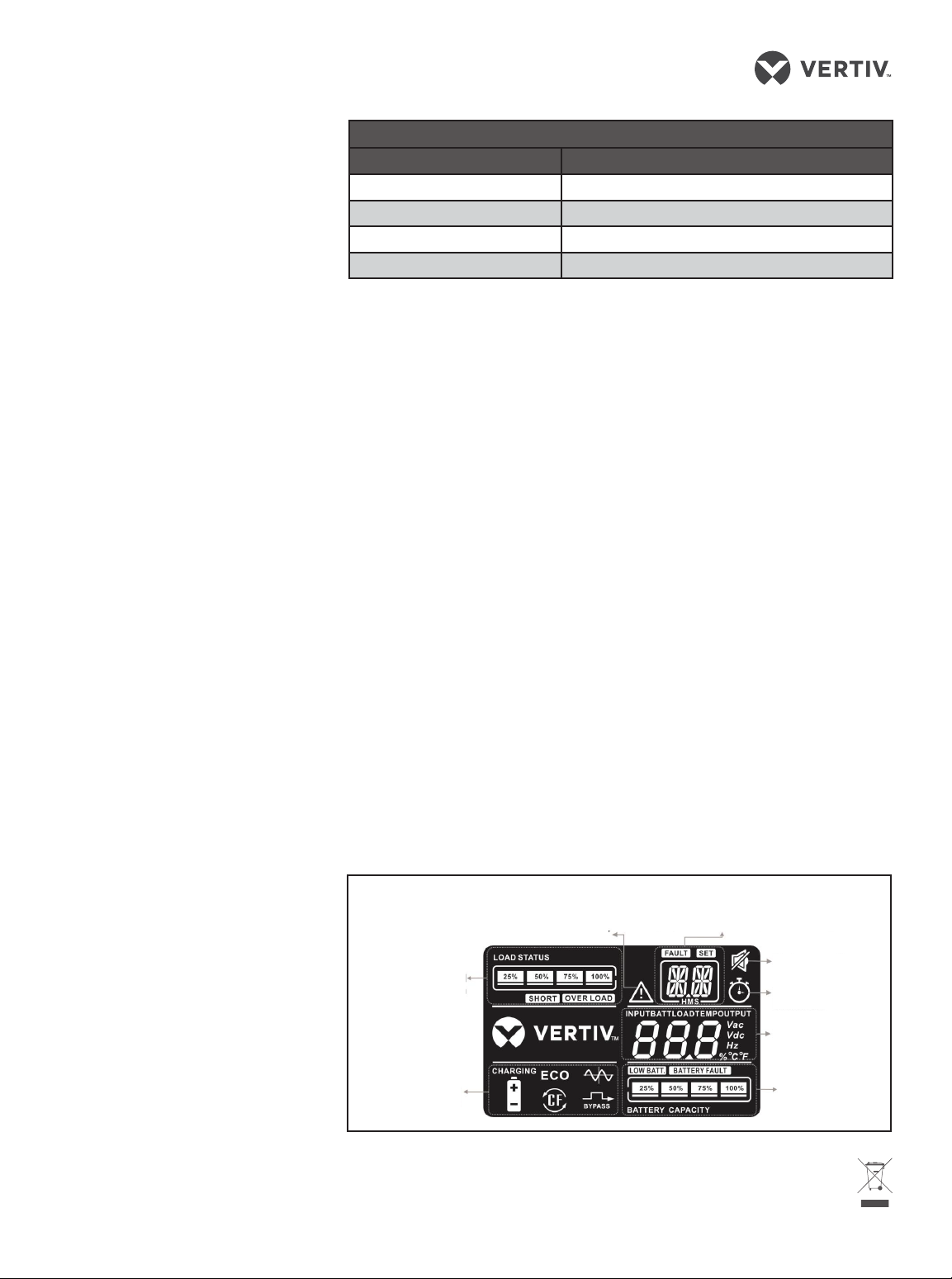
Painel de operação e display
Indicador de advertência
Informações de falha e advertência/Operação de
configuração/Configuração de tempo de backup
Operação em mudo
Indicador de tempo
de backup
Informações do
UPS
Informações
de bateria
Informações
de carga
Informações de
modo de operação
FIAÇÃO
Modelo Disjuntor externo recomendado
GXTRT-1000LVRT2UXLB 15 A
GXTRT-1500LVRT2UXLB 15 A
GXTRT-2000LVRT2UXLB 20 A
GXTRT-3000LVRT2UXLB 30 A
This manual suits for next models
4
Table of contents
Languages:
Popular DC Drive manuals by other brands

Siemens
Siemens SINAMICS PERFECT HARMONY GH180 operating instructions

YASKAWA
YASKAWA PROFINET V1000 installation manual

WEG
WEG CFW300-KHMIR Installation, configuration and operations guide

YASKAWA
YASKAWA JOHB-SMP3 Technical manual

National Instruments
National Instruments ISM-7411 Getting started

Siemens
Siemens 3VT9100-3M.00 operating instructions