manuals.online logo
Brands
  1. Home
  2. •
  3. Brands
  4. •
  5. Vertiv
  6. •
  7. Enclosure
  8. •
  9. Vertiv Liebert ITA2 User manual

Vertiv Liebert ITA2 User manual

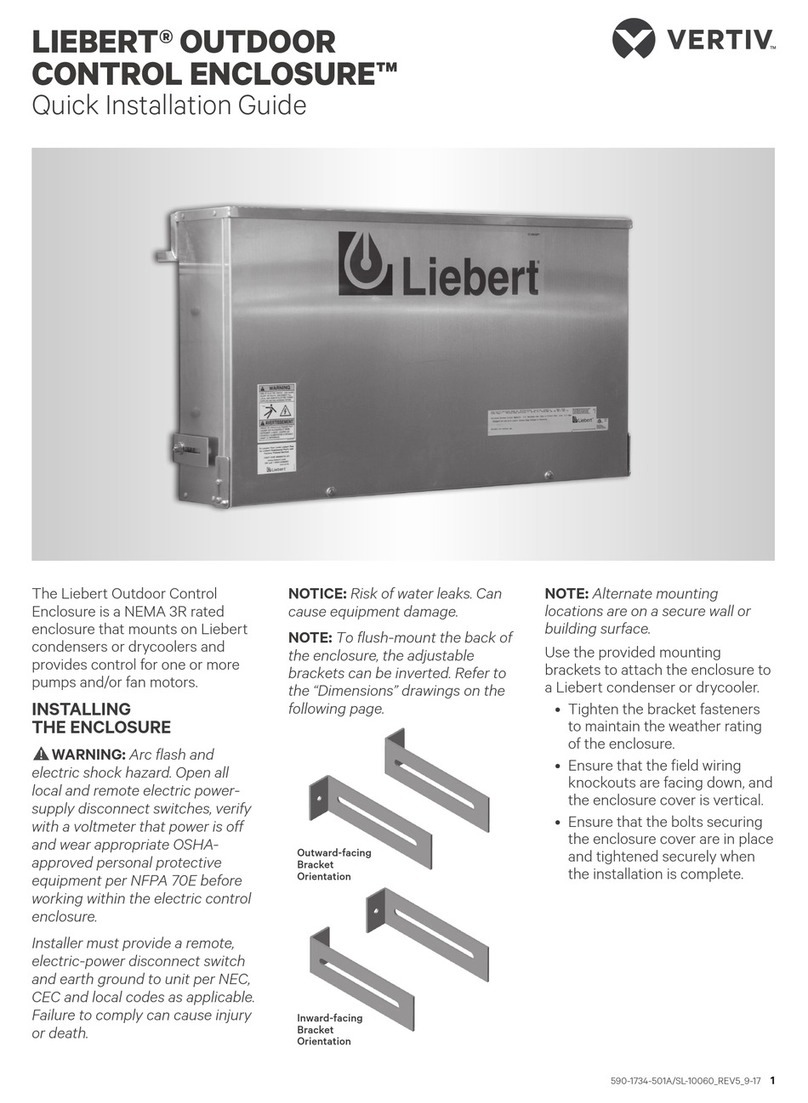
VERTIV™ LIEBERT® ITA2
BATTERY CABINET
Quick Installation Guide
SL-26257QS_REV2_06-20 1
I M P O R TA N T: Before installing,
connecting to supply or operating
your Liebert ITA2 Battery Cabinet,
please review the Safety and
Regulatory Statements sheet. For
detailed installation, operating,
maintenance and troubleshooting
information visit the Liebert ITA2
product page for the Liebert ITA2
Battery Cabinet Installer/User
Guide available at www.Vertiv.com
or use the QR code below.
INSPECT THE BATTERY
CABINET
Inspect the cabinet for any signs of
obvious damage. If damage is
visible, do not proceed. File a
damage claim with the carrier
immediately and send a copy to:
Vertiv
1050 Dearborn Drive
P.O. Box 29186
Columbus OH 43085
Attn. Traic Department
INSTALL THE BATTERY
INSULATING PLATES
NOTE: Only on UPS models with
terminal block battery connectors.
Do not reverse the polarity of the
battery cables.
IMPORTANT!Beforeconnectingthe
battery cables, ensure that the
battery breaker on the rear of the
battery cabinet is open (O).
1. Connect the ground wire (PE)
to the ground screw on the
rear of the UPS.
2. Place the battery cable ring
lug on the terminal block, add
the insulating plate, then insert
the screw and tighten to
30 lb.- in. torque.
3. Repeat Step 2 for each
terminal-block connection:
battery +, battery neutral, and
battery –).
Insulating Plates
LIEBERT® ITA2 BATTERY CABINET
Quick Installation Guide
2 SL-26257QS_REV2_06-20
CONNECTING 3U CABINET
SYSTEMS
Each battery string is made up of
two battery cabinets that are
connected to the UPS in parallel.
1. Connect a single battery
cabinet system.
Refer to the illustration, “Cabling
3U Cabinets in Parallel,” above,
and connect the UPS-to-
battery cable to Connectors A
on each battery cabinet in the
battery string.
2. Connect the
communication cable.
Connect to the communication
port on the UPS and
Communication Port 1 on the
rst battery cabinet.
3. Connect the rst string of
additional battery cabinet
systems.
Connect a battery-to-battery
cable to Connector B on the
rst cabinet in the previous
string, and to Connector A on
rst cabinet in the additional
string.
4. Connect the second
string in additional
battery cabinet systems.
Connect a battery-to-battery
cable to Connector B on the
second cabinet in the previous
string, and to Connector A on
rst cabinet in the additional
string.
5. Connect the
communication cable.
Connect to Communication
Port 2 on the rst cabinet in the
previous string to
Communication Port 1 on the
rst cabinet in the second
string.
6. Close Breakers.
When connections are
complete, close the battery
output breaker(s).
Cabling 3U Cabinets in Parallel
BAT-
BAT N
BAT+
Ground screw
(PE)
Communication
port
String 1
String 2
5
3
4
UPS
2
1
LIEBERT® ITA2 BATTERY CABINET
Quick Installation Guide
SL-26257QS_REV2_06-20 3
CONNECTING 2U CABINET
SYSTEMS
Each battery string is made up of
two battery cabinets that are
connected to the UPS in parallel.
1. Connect a single battery
cabinet system.
Refer to the illustration,
“Cabling 2U Cabinets in
Parallel,” above, and connect
the “Port-B” end of the battery
cables to the battery ports on
the UPS.
Connect the “Port-A” end of
each cable to Connector A on
each battery cabinet in the
battery string.
2. Connect the
communication cable.
Connect to the communication
port on the UPS and one of the
communication ports on the
rst battery cabinet.
3. Connect the rst string of
additional battery cabinet
systems.
Connect a battery cable to
Connector B on the rst
cabinet in the previous string,
and to Connector A on the rst
cabinet in the additional string.
4. Connect the second
string in additional
battery cabinet systems.
Connect a battery cable to
Connector B on the second
cabinet in the previous string,
and to Connector A on the rst
cabinet in the additional string.
5. Connect the
communication cable
Connect a cable between the
RJ-45 communication ports
between each battery cabinet.
6. Set the DIP switches.
Referring to the DIP Switch
illustration, above, and the
table, above right, set the DIP
switch on both cabinets in
each additional string.
7. Close Breakers.
When connections and DIP
switch settings are complete,
close the battery output
breaker(s).
DIP Switch Settings for 2U Battery Cabinet Strings
STRING
CABINET
DIP SWITCH POSITION
Group
Num
1
2
3
4 5
6
1AO O O O O On
BO O O O On O
2
AO O O O On On
BO O O On O O
3
AO O O On O On
BO O O On On O
4
AO O O On On On
BO O On O O O
5
AO O On O O On
BO O On O On O
DIP Switch
Group
Num
Cabling 2U Cabinets in Parallel
To contact Vertiv Technical Support: visit www.Vertiv.com
© 2020 Vertiv Group Corp. All rights reserved. Vertiv™ and the Vertiv logo are trademarks or registered trademarks of Vertiv Group Corp. All other names and logos referred to are
trade names, trademarks or registered trademarks of their respective owners. While every precaution has been taken to ensure accuracy and completeness herein, Vertiv Group
Corp. assumes no responsibility, and disclaims all liability, for damages resulting from use of this information or for any errors or omissions. Specications are subject to change
without notice.
4 SL-26257QS_REV2_06-20

Other manuals for Liebert ITA2

10

Other Vertiv Enclosure manuals

Vertiv NetXtend Flex 20 Operating and installation instructions

Vertiv

Vertiv NetXtend Flex 20 Operating and installation instructions

Vertiv XTE 802 Series Operating and installation instructions

Vertiv

Vertiv XTE 802 Series Operating and installation instructions

Vertiv NetXtend Flex 20 Operating and installation instructions

Vertiv

Vertiv NetXtend Flex 20 Operating and installation instructions

Vertiv NetSure 211 Series User manual

Vertiv

Vertiv NetSure 211 Series User manual

Vertiv XTE 601E Series Operating and installation instructions

Vertiv

Vertiv XTE 601E Series Operating and installation instructions

Vertiv XTE 801 Series Operating and installation instructions

Vertiv

Vertiv XTE 801 Series Operating and installation instructions

Vertiv InstaRack LAN User manual

Vertiv

Vertiv InstaRack LAN User manual

Vertiv Liebert User manual

Vertiv

Vertiv Liebert User manual

Vertiv Ultracab Cross-Connect Operating and installation instructions

Vertiv

Vertiv Ultracab Cross-Connect Operating and installation instructions

Vertiv NetSure 211 Series User manual

Vertiv

Vertiv NetSure 211 Series User manual

Popular Enclosure manuals by other brands

Panduit PZWRKA installation instructions

Panduit

Panduit PZWRKA installation instructions

SilverStone ML04B instruction manual

SilverStone

SilverStone ML04B instruction manual

Akasa A-RA08-A2B installation manual

Akasa

Akasa A-RA08-A2B installation manual

Cooler Master ATCS 840 installation guide

Cooler Master

Cooler Master ATCS 840 installation guide

Wesena e7T Operator's manual

Wesena

Wesena e7T Operator's manual

Spectris Bruel & Kjaer Vibro AC-2114 manual

Spectris

Spectris Bruel & Kjaer Vibro AC-2114 manual

One Stop Systems nanoCUBE quick start guide

One Stop Systems

One Stop Systems nanoCUBE quick start guide

Pulsar AWO610 quick start guide

Pulsar

Pulsar AWO610 quick start guide

Macpower & Tytech Hydra S2 user manual

Macpower & Tytech

Macpower & Tytech Hydra S2 user manual

Tecnoware FBBEVD4003RT Series user manual

Tecnoware

Tecnoware FBBEVD4003RT Series user manual

ENERMAX MarbleShell MS30 user manual

ENERMAX

ENERMAX MarbleShell MS30 user manual

Vimar ELVOX EIC5 Installation and operation manual

Vimar

Vimar ELVOX EIC5 Installation and operation manual

RIHO HAMAR 2.0 R309 Quadrant installation manual

RIHO

RIHO HAMAR 2.0 R309 Quadrant installation manual

Hama Fire Wire Combo operating instructions

Hama

Hama Fire Wire Combo operating instructions

Advantech MIC-3039 user manual

Advantech

Advantech MIC-3039 user manual

nCase M1 Assembly manual

nCase

nCase M1 Assembly manual

StarTech.com INFOSAFE IDE2510U2 user guide

StarTech.com

StarTech.com INFOSAFE IDE2510U2 user guide

MTX Bass Slammer FEN10U Installation directions

MTX

MTX Bass Slammer FEN10U Installation directions

manuals.online logo
manuals.online logoBrands
  • About & Mission
  • Contact us
  • Privacy Policy
  • Terms and Conditions

Copyright 2025 Manuals.Online. All Rights Reserved.