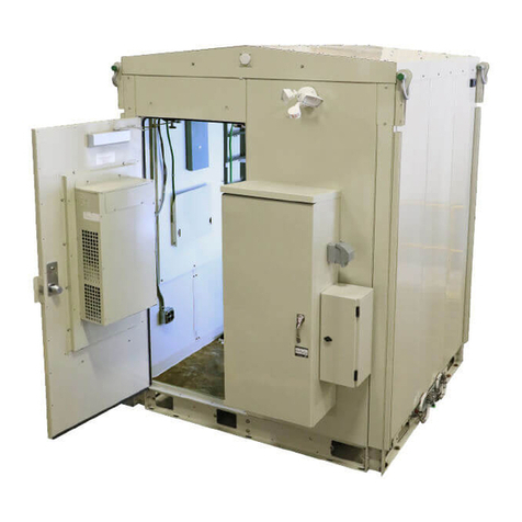
Vertiv XTE 801 Series Operating and installation instructions

XTE 802 Series
Walk-In-Cabinet (WIC)
Description and Installation Manual (631-205-434), Revision D
Specification Number: F2018009

Vertiv |XTE 802 Series Walk-In-Cabinet (WIC) Description & Installation Manual (631-205-434)|Rev. D
2
The information contained in this document is subject to change without
notice and may not be suitable for all applications. While every precaution
has been taken to ensure the accuracy and completeness of this
document, Vertiv Group Corporation assumes no responsibility and
disclaims all liability for damages resulting from use of this information or
for any errors or omissions. Refer to other local practices or building codes
as applicable for the correct methods, tools, and materials to be used in
performing procedures not specifically described in this document.
This document may contain confidential and/or proprietary information of
Vertiv Group Corporation, and its receipt or possession does not convey
any right to reproduce, disclose its contents, or to manufacture or sell
anything that it may describe. Reproduction, disclosure, or use without
specific authorization from Vertiv Group Corporation is strictly prohibited.
Vertiv and the Vertiv logo are trademarks or registered trademarks of
Vertiv Co. All other names and logos referred to are trade names,
trademarks or registered trademarks of their respective owners.
© 2019 Vertiv Co. All rights reserved.

Vertiv |XTE 802 Series Walk-In-Cabinet (WIC) Description & Installation Manual (631-205-434)|Rev. D
3
TABLE OF CONTENTS
Admonishments Used in this Document............................................................6
Important Safety Instructions ..............................................................................7
Safety Precautions Definitions..................................................................................................................7
General Safety Precautions..........................................................................................................................7
Voltages.......................................................................................................................................................................... 8
AC Input Voltages........................................................................................................................................................8
DC Output and Battery Voltages ..................................................................................................................8
Battery .............................................................................................................................................................................. 8
Specific Safety Precautions ......................................................................................................................10
Personal Protective Equipment (PPE)...........................................................................................13
Hazardous Voltage............................................................................................................................................13
Handling Equipment Containing Static Sensitive Components...........................13
Maintenance and Replacement Procedures............................................................................13
Static Warning.........................................................................................................14
Purpose of this Document ................................................................................... 15
Product Description............................................................................................... 15
General...........................................................................................................................................................................15
Part Numbers ..........................................................................................................................................................16
Application .................................................................................................................................................................18
Standards Compliance...................................................................................................................................18
Safety Listed AC or DC Components..............................................................................................19
Commercial AC Service................................................................................................................................20
WIC Dimensions, Weights, and Physical Specifications................................................ 21
WIC Features and Options ........................................................................................................................28
Sequence of Procedures...................................................................................... 46
General..........................................................................................................................................................................46
Front Door ............................................................................................................... 47
Safety Precautions ............................................................................................................................................47
Locking Mechanism.........................................................................................................................................47
Securing Mechanism ......................................................................................................................................47
Intrusion Alarm Switch Operation...................................................................................................... 47
Installation Considerations................................................................................. 48
Important Safety Instructions ................................................................................................................48
Installation Overview.......................................................................................................................................48
Tools and Test Equipment Required for Installation......................................................49
WIC and Generator Placement........................................................................... 50
Overview......................................................................................................................................................................50
Site Selection ..........................................................................................................................................................50
WIC Foundation Kit Installation.............................................................................................................51
WIC Helical Foundation Kit Installation (P/N D1000-0000-0101) .............................51

Vertiv |XTE 802 Series Walk-In-Cabinet (WIC) Description & Installation Manual (631-205-434)|Rev. D
4
WIC Concrete Pier/Pad Foundation Kit Installation (P/N D1007-0000-
0012)......................................................................................................................................................................................55
WIC On The Ground (Gravity) Foundation Kit Installation (P/N D1000-
0000-0103)..................................................................................................................................................................... 57
Generator Foundation Kit Installation............................................................................................58
All Generators up to 20 KW Helical Foundation Kit Installation (P/N
D1000-0010-0109)..................................................................................................................................................58
All Generators up to 30 KW Helical Foundation Kit Installation (P/N
D1000-0010-0109, Two Required).........................................................................................................60
All Generators up to 30 KW On the Ground (Gravity) Foundation Kit
Installation (P/N D1001-0020-0062).....................................................................................................62
WIC and Generator Combo Platform Installation...............................................................63
WIC and Generator Combo Helical Platform Installation (P/N D1000-
0010-0122).......................................................................................................................................................................63
WIC and Generator Combo Concrete/Gravity Platform Installation (P/N
D1000-0010-0123).................................................................................................................................................. 66
Generator Wings Installation (P/N D1000-0020-0032)..................................................... 68
Elevated WIC and Generator Platform Installation (P/N D1000-0010-
0089-04, P/N D1000-0010-0089-06, P/N D1000-0010-0089-08, P/N
D1000-0010-0089-10, P/N D1000-0010-0089-12).................................................................71
Transportation and Storage .....................................................................................................................73
Unpacking and Preparing the WIC at the Installation Site.......................................74
Preparing to Lift the WIC............................................................................................................................ 75
Lifting the WIC........................................................................................................................................................77
Placing the WIC.................................................................................................................................................... 79
On Approved Foundation Kit .........................................................................................................................79
Sealing Cable Entries............................................................................................. 81
Grounding the WIC................................................................................................ 82
Important Safety Instructions ................................................................................................................82
Safety Precautions ............................................................................................................................................82
General..........................................................................................................................................................................82
Exterior Ground Bars ......................................................................................................................................82
Master Ground Bar (MGB) ........................................................................................................................83
GPS Mounting Brackets...............................................................................................................................83
AC Power ..................................................................................................................91
Important Safety Instructions .................................................................................................................91
Safety Precautions .............................................................................................................................................91
General...........................................................................................................................................................................91
WIC AC Schematic.............................................................................................................................................91
AC Input Connections to Power Transfer Load Center (PTLC) E/W
Automatic Transfer Switch (ATS).....................................................................................................92
DC Power ................................................................................................................ 101
Important Safety Instructions ..............................................................................................................101
Safety Precautions ..........................................................................................................................................101
General........................................................................................................................................................................101

Vertiv |XTE 802 Series Walk-In-Cabinet (WIC) Description & Installation Manual (631-205-434)|Rev. D
5
DC Power Cabling Color Scheme.....................................................................................................101
Battery Installation and Wiring............................................................................................................101
External DC Generator Wiring............................................................................................................ 102
Procedure....................................................................................................................................................................... 102
Operating the Power System............................................................................................................... 102
OSP Cables............................................................................................................ 106
Important Safety Instructions .............................................................................................................106
Safety Precautions.........................................................................................................................................106
Sealing Cable Entries...................................................................................................................................106
Installing Fiber Cables.................................................................................................................................106
Alarm Wiring ..........................................................................................................107
Connecting External Alarms..................................................................................................................107
Initial Power Up.................................................................................................... 109
Important Safety Instructions .............................................................................................................109
Safety Precautions.........................................................................................................................................109
Prerequisite ...........................................................................................................................................................109
Initial Power Up Sequence ......................................................................................................................110
Direct Air Cooling (DAC) and HVAC ................................................................ 111
Description................................................................................................................................................................111
General Operation..............................................................................................................................................111
Controller...................................................................................................................................................................114
DC Power, Outdoor Enclosure & Service Contacts.....................................123

Vertiv |XTE 802 Series Walk-In-Cabinet (WIC) Description & Installation Manual (631-205-434)|Rev. D
6
ADMONISHMENTS USED IN THIS DOCUMENT
DANGER
! Warns of a hazard the reader
will
be exposed to that will
likely
result
in death or serious injury if not avoided
. (ANSI, OSHA)
WARNING
! Warns of a potential hazard the reader
may
be exposed to that
could
result in
death or serious injury if not avoided
. This admonition is not used for situations that pose
a risk only to equipment, software, data, or service
. (ANSI)
CAUTION
! Warns of a potential hazard the reader
may
be exposed to that
could
result in minor or moderate injury if not avoided
. (ANSI, OSHA) This admonition is not
used for situations that pose a risk only to equipment, data, or service, even if such use
appears to be permitted in some of the applicable standards
. (OSHA)
ALER
T! Alerts the reader to an action that
must be avoided
in order to protect
equipment, software, data, or service
. (ISO)
ALERT
! Alerts the reader to an action that
must be performed
in order to prevent
equipment damage, software corruption, data loss, or service interruption
. (ISO)
FIRE SAFETY
! Informs the reader of fire safety information, reminders, precautions,
or policies, or of the locations of fire
-fighting and fire-safety equipment. (ISO)
SAFETY
! Informs the reader of general safety information, reminders, precautions, or
policies not related to a particular source of hazard or to fire safety
. (ISO, ANSI, OSHA)

Vertiv |XTE 802 Series Walk-In-Cabinet (WIC) Description & Installation Manual (631-205-434)|Rev. D
7
IMPORTANT SAFETY INSTRUCTIONS
Safety Precautions Definitions
Definitions of the safety admonishments used in this document are listed under “Admonishments Used in this
Document” on page 6.
General Safety Precautions
The following precautions shall be observed at all time when handling and installing the WIC:
•Observe all safety precautions against personal injury and equipment damage.
•The procedures outlined in this manual are only recommended guidelines. Ensure that all NEC (National
Electric Code) and local codes for safety and wiring are followed.
-Use listed two-hole compression connectors (lugs) to terminate all ground connections. Selected
lug shall match wire and type, and crimped applied as specified by the lug manufacturer.
-Apply NO-OX-ID-A to all ground connections.
-Insulation of field-wire conductors should be rated no less than 105 °C, and sized in a manner that is
consistent with the NEC and local codes.
•Always use a non-contact voltage detector, when approaching the WIC, to verify no leaks or shorts are
presents on the external body.
•Read “WIC and Generator Placement” on page 50 in its entirety prior to attempting to handle or secure
the WIC.
•A minimum of two persons are required to safely install the WIC.
•Hard hats and steel-toed boots should be worn while maneuvering the WIC.
•Safety glasses should always be on while on-site.
•Safety gloves should be on when working in temperature extremes, with batteries, or with sharp objects.
•All electricians, operators, and technicians have been trained for the task at hand.
•Keep bystanders away.
•Ensure that all personnel on site are familiar with the first-aid kit location and emergency procedures in
the event of an injury.
•Never leave the WIC unattended. If leaving the site, close and secure the WIC.

Vertiv |XTE 802 Series Walk-In-Cabinet (WIC) Description & Installation Manual (631-205-434)|Rev. D
8
You Must Follow Approved Safety Procedures
DANGER! Performing the following procedures may expose you to hazards. These procedures should
be performed by qualified technicians familiar with the hazards associated with this type of equipment.
These hazards may include shock, energy, and/or burns. To avoid these hazards:
a) The tasks should be performed in the order indicated.
b) Remove watches, rings, and other metal objects.
c) Prior to contacting any uninsulated surface or termination, use a voltmeter to verify that no voltage
or the expected voltage is present. Check for voltage with both AC and DC voltmeters prior to
making contact.
d) Wear eye protection.
e) Use certified and well maintained insulated tools. Use double insulated tools appropriately rated for
the work to be performed.
Voltages
AC Input Voltages
DANGER! This system operates from AC input voltage capable of producing fatal electrical shock. AC
input power must be completely disconnected from the branch circuits wiring used to provide power to
the system before any AC electrical connections are made. Follow local lockout/tagout procedures to
ensure upstream branch circuit breakers remain de-energized during installation. DO NOT apply AC
input power to the system until all electrical connections have been completed and checked.
DC Output and Battery Voltages
DANGER! This system produces DC power and may have a battery source connected to it. Although
the DC voltage is not hazardously high, the rectifiers and/or battery can deliver large amounts of current.
Exercise extreme caution not to inadvertently contact or have any tool inadvertently contact an output
terminal or battery terminal or exposed wire connected to an output terminal or battery terminal.
NEVER allow a metal object, such as a tool, to contact more than one termination or battery terminal at a
time, or to simultaneously contact a termination or battery terminal and a grounded object. Even a
momentary short circuit can cause sparking, explosion, and injury.
Battery
Refer to the battery manufacturer documentation for specific battery safety instructions. The following are
general guidelines.
WARNING! Correct polarity must be observed when connecting battery leads.
WARNING! Special safety precautions are required for procedures involving handling, installing, and
servicing batteries. Observe all battery safety precautions in this manual and in the battery instruction
manual. These precautions should be followed implicitly at all times.

Vertiv |XTE 802 Series Walk-In-Cabinet (WIC) Description & Installation Manual (631-205-434)|Rev. D
9
WARNING! A battery can present a risk of electrical shock and high short circuit current. Servicing of
batteries should be performed or supervised only by properly trained and qualified personnel
knowledgeable about batteries and the required precautions.
The following precautions should be observed when working on batteries:
•Remove watches, rings, and other metal objects.
•Eye protection should be worn to prevent injury from accidental electrical arcs.
•Use certified and well maintained insulated tools. Use double insulated tools appropriately rated for
the work to be performed. Ensure that wrenches with more than one working end have only one
end exposed.
•Do not lay tools or metal parts on top of batteries.
•Disconnect charging source prior to connecting or disconnecting battery terminals.
•Risk of explosion if battery is replaced with an incorrect type or if polarity is reversed.
Recommended to replace batteries with the same manufacturer and type, or equivalent.
•Dispose of used batteries according to the instructions provided with the batteries. Do not dispose
of batteries in a fire. They may explode.
•ALWAYS FOLLOW THE BATTERY MANUFACTURER’S RECOMMENDATIONS AND SAFETY
INSTRUCTIONS.
DANGER! This equipment may be used in conjunction with lead-acid batteries. Working near lead-acid
batteries is dangerous!
In addition to the hazard of electric shock, gas produced by batteries can be explosive and sulfuric acid
can cause severe burns.
•Do not open or mutilate batteries. Released electrolyte is harmful to the skin and eyes, and is toxic.
•Batteries contain sulfuric acid.
•Batteries generate explosive gases during normal operation. Systems containing batteries should
never be installed in an airtight room or space. Only install in a ventilated environment.
•Batteries are an energy source that can produce high amounts of electrical current.
FOR THESE REASONS, IT IS OF CRITICAL IMPORTANCE THAT YOU READ THESE INSTRUCTIONS
AND FOLLOW THEM EXACTLY.
WHEN WORKING WITH LEAD-ACID BATTERIES:
•Follow the recommended PPE requirements per the SDS for the battery to be used.
•If battery acid enters your eye, immediately flush your eye with running cold water for at least 15
minutes. Get medical attention immediately.
•If battery acid contacts skin or clothing, wash immediately with soap and water.

Vertiv |XTE 802 Series Walk-In-Cabinet (WIC) Description & Installation Manual (631-205-434)|Rev. D
10
ALERT! Performing maintenance and/or troubleshooting procedures may interrupt power to the loads,
if battery reserve is not sufficient.
Specific Safety Precautions
DANGER! RISK OF ELECTRICAL SHOCK, GENERAL
All ground connections must be installed and verified prior to connecting any power cables (AC or DC)
and turning-up the WIC.
When connecting any discrete power connection, make the connection first with the ground/return and
break last with ground/return.
Do not install equipment showing any physical damage.
DANGER! RISK OF ELECTRICAL SHOCK, AC
Proper actions, include, but not limited to:
a) Verify before contacting the WIC that no current leakage or ground fault condition is present.
b) Verify a proper ground is in place.
c) Verify for AC hook-up, all WIC circuit breakers are OFF and the utility incoming feed is OFF.
Use a trained licensed electrician.
DANGER! RISK OF ELECTRIC SHOCK
The DC bus is powered by DUAL power sources – Rectifiers and DC Batteries.
To properly work on the system, de-energize by disconnecting BOTH power sources. Even with the
batteries turned off by using a local battery (circuit breaker) disconnect, batteries are still “LIVE” and
hazardous, including a voltage >50 VDC, and a source of high short circuit current.
Use extreme caution around the batteries and terminals.
DANGER! RISK OF ELECTRICAL SHOCK, OSP CABLES
If joint buried cables are used, check the cable sheath for voltage in accordance with local standards. If
voltage is detected, do not proceed with the installation. Contact the supervisor and do not proceed
until the voltage hazard is eliminated.
DANGER! RISK OF CHEMICAL EXPOSURE
A battery can present harmful chemicals. Refer to the battery installation manuals and MSDS supplied
with the batteries. Work in a ventilated area and follow all safety procedures.
At a minimum, wear safety glasses and gloves when working with batteries.
Do not smoke.

Vertiv |XTE 802 Series Walk-In-Cabinet (WIC) Description & Installation Manual (631-205-434)|Rev. D
11
WARNING! PREVENT INJURIES, FROM LIFTING THE WIC
Follow all local safety practices while lifting the WIC. Safety equipment, signage, traffic control and all
required Personal Protective Equipment (PPE) shall be used.
Keep unnecessary personnel and bystanders clear of work areas at all times.
Do not lift the WIC over people. Do not let anyone work, stand, or pass under a lifted WIC.
Do not move or lift the WIC with a door open.
Only properly trained and certified operators shall operate any crane or lifting equipment.
Do not allow the lifting equipment or WIC to touch any electrical wiring or equipment.
Operate all lifting equipment within safety constraints, as defined by the manufacturer and local
practices; for example, do not exceed the capacity of reach.
Crane Operation:
Only properly trained operators shall operate the crane.
Do not operate the crane until all stabilizers are extended. The stabilizers must be in firm contact with
the ground or other adequate support structure. Do not retract or extend the stabilizers when the WIC
is suspended from the crane.
Only the crane rigging crew should set up the crane and rigging.
Do not exceed the lifting capacity of the crane.
Use all four (4) provided lifting points (eyes) at the top corners of the WIC to lift the WIC.
Use crane spreader frames to prevent WIC framework warping due to side loading.
Never route straps, cables or chains through the fork-lift channels in the base for a vertical crane lift.
Do not use slings, clevises or shackles of insufficient capacity.
Forklift Operation:
Only properly trained operators shall operate the forklift.
Do not exceed the lifting capacity of the forklift.
Forklifts shall have a minimum fork length of 72 inches (183 cm).

Vertiv |XTE 802 Series Walk-In-Cabinet (WIC) Description & Installation Manual (631-205-434)|Rev. D
12
CAUTION! PREVENT EQUIPMENT DAMAGE, PROPER HANDLING
Do not stack nor lay the WIC on its side.
Similarly, do not stack batteries or lay them on their side. Do not tip batteries -- keep in upright position
at all times.
DANGER! PREVENT EQUIPMENT DAMAGE, MAINTAIN VENTILATION
To optimize the service life of this equipment, make sure there are no obstructions in front of the
ventilation openings.
WARNING! RISK OF INJURY TO EYES AND SKIN, FROM OPTIC DEVICES
Do not look into a fiber cable or device, nor hold such cable or device against body, fabric or other
material.
WARNING! RISK OF HAZARDOUS SUBSTANCES
After handling of the WIC or any such component, such as batteries, cables, busbars, etc., always wash
hands immediately after.
WARNING! RISK OF EXPLOSION
For safety reasons, never restrict or block the airflow through the door or entry panel ventilation
openings.
CAUTION! PREVENT EQUIPMENT DAMAGE, FROM CONDENSATION
Until the WIC is turned up for service, the bags of desiccant shipped with the WIC must remain in the
WIC to prevent condensation.
Once service is in-place, remove the desiccant.
CAUTION! PREVENT EQUIPMENT DAMAGE, OPERATING TEMPERATURE
The WIC is approved for operation in an environment with an expected temperature range of -40 °F to
+115 °F (–40 °C to +46 °C) and 0% to 95% relative humidity range, condensing. Do not use at
temperatures or humidity exceeding these ranges.
The WIC is not for indoor use.
CAUTION! PREVENT DAMAGES CAUSED BY ELECTROSTATIC DISCHARGES (ESD)
When handling equipment containing static sensitive components, wear an appropriate antistatic device
(a wrist strap for example) that is properly connected to a designated antistatic grounding point (on a
framework, on an anti-static floor mat, etc.). ESD-protective packaging material shall also be used when
carrying/shipping equipment containing static sensitive components.

Vertiv |XTE 802 Series Walk-In-Cabinet (WIC) Description & Installation Manual (631-205-434)|Rev. D
13
Personal Protective Equipment (PPE)
DANGER! ARC FLASH AND SHOCK HAZARD.
Appropriate PPE and tools required when working on this equipment. An appropriate flash protection
boundary analysis should be done determine the “hazard/risk” category, and to select proper PPE.
Only authorized and properly trained personnel should be allowed to install, inspect, operate, or maintain
the equipment.
Do not work on LIVE parts. If required to work or operate live parts, obtain appropriate Energized Work
Permits as required by the local authority, per NFPA 70E “Standard for Electrical Safety in the
Workplace”.
Hazardous Voltage
DANGER! HAZARD OF ELECTRICAL SHOCK.
More than one disconnect may be required to de-energize the system before servicing.
Handling Equipment Containing Static Sensitive Components
ALERT! Installation or removal of equipment containing static sensitive components requires careful
handling. Before handling any equipment containing static sensitive components, read and follow the
instructions contained on the Static Warning Page.
Maintenance and Replacement Procedures
CAUTION! When performing any step in procedures that requires removal or installation of hardware,
use caution to ensure no hardware is dropped and left inside the unit; otherwise service interruption or
equipment damage may occur.
NOTE!
When performing any step in procedures that requires removal of existing hardware, retain all
hardware for use in subsequent steps, unless otherwise directed.

Vertiv |XTE 802 Series Walk-In-Cabinet (WIC) Description & Installation Manual (631-205-434)|Rev. D
14
STATIC WARNING
This equipment contains static sensitive components. The warnings listed below must be observed to
prevent damage to these components. Disregarding any of these warnings may result in personal injury
or damage to the equipment.
1. Strictly adhere to the procedures provided in this document.
2. Before touching any equipment containing static sensitive components, discharge all static
electricity from yourself by wearing a wrist strap grounded through a one megohm resistor. Some
wrist straps have a built-in one megohm resistor; no external resistor is necessary. Read and follow
wrist strap manufacturer’s instructions outlining use of a specific wrist strap.
3. Do not touch traces or components on equipment containing static sensitive components. Handle
equipment containing static sensitive components only by the edges that do not have connector
pads.
4. After removing equipment containing static sensitive components, place the equipment only on
conductive or anti-static material such as conductive foam, conductive plastic, or aluminum foil. Do
not use ordinary Styrofoam™or ordinary plastic.
5. Store and ship equipment containing static sensitive components only in static shielding containers.
6. If necessary to repair equipment containing static sensitive components, wear an appropriately
grounded wrist strap, work on a conductive surface, use a grounded soldering iron, and use
grounded test equipment.

Vertiv |XTE 802 Series Walk-In-Cabinet (WIC) Description & Installation Manual (631-205-434)|Rev. D
15
PURPOSE OF THIS DOCUMENT
This document provides description and installation instructions for the XTE 802 Series Walk-In-Cabinet (WIC);
Spec. No. F2018009, including associated foundation kits and platforms.
When using this document, consider the footprint for the XTE 802 Series Walk-In-Cabinet (WIC) you are
installing as well as any installed options when determining which procedures contained within this document
will be applicable for your installation.
Procedures related to the provisioning, start-up, and acceptance of associated telecom equipment are not
covered in this document.
Documents that supplement the information in this document are referenced in “Sequence of Procedures” on
page 46.
PRODUCT DESCRIPTION
General
The XTE 802 Series Walk-In-Cabinet (WIC) ensures vital electronic equipment is protected from vandalism and
environmental damage. The XTE 802 Series Walk-In-Cabinet (WIC) may be equipped with a NetSure™ 7100
Power System (-48 VDC at 1000 amps, +24 VDC at 500 amps, 3 row distribution). The XTE 802 Series Walk-
In-Cabinet (WIC) offers an array of climate control, remote monitoring and control, power, mounting and
configuration options. See Figure 1for overall views of the XTE 802 Series Walk-In-Cabinet (WIC).
Figure 1:
Overall Views of XTE 802 Series Walk-In-Cabinet (WIC)
Front Rear

Vertiv |XTE 802 Series Walk-In-Cabinet (WIC) Description & Installation Manual (631-205-434)|Rev. D
16
Part Numbers
Refer to Table 1for applicable product part numbers.
Table 1:
XTE 802 Series Walk-In-Cabinet (WIC) Part Numbers and Descriptions
Part Number Description NEQ
XTE 802 Series Walk-In-Cabinet (WIC)
F2018009
ATT 6X6 WIC e/w as detailed below.
NEQ.20060
Electrical Service Entrance
PTLC-ATS-3S-12200-
CL_ATT
UL 891 Listed, 32x22*x10 cabinet with CamLok Connector
Panel, 240 VAC / 120 VAC, 200 A Power Transfer Load Center
with automatic transfer between Utility and an Alternative
Power Source permanently connected or temporarily
connected via CamLok style connectors. PTLC includes
ASCO 510 Series TVSS surge protection, a 30-position Square
D NQ panelboard, and an alarm monitor for utility power loss
SPD fail, and generator. (Vertiv P/N 151840.)
NEQ.20110
DC Power System
582127000203 NetSure™ 7100 SERIES -48V DC Power System sized at 1,000
Amp on the -48 VDC side and 500 A on the +24 VDC side
with 3 factory-installed and wired battery trays.
NEQ.20068
Additional Equipment
PTS 3703-WIC WOF
Rack CommBay-WIC-without Fiber Panel.
NEQ.19678
PTS3704-WIC-WF
Rack CommBay-WIC-with Fiber Panel.
NEQ.19679
DAC2000S000-299-VAR-
0013
Direct Air Cooling (DAC) system. Dual Fan -48 VDC powered
fresh air cooling kit with HVAC control for low voltage (24
VAC) controlled HVAC unit. (Vertiv P/N 151903.)
N/A
ECUA18ACA036S-A5-299-
VAR-0018
1.5 TON WALL MOUNTED HVAC, with controller, supply and
return grills and remote sensor (Vertiv P/N 151916).
N/A
WIC Foundation Options
D1000-0000-0101
WIC Helical Foundation Kit – (4) WIC Corner Plates, (1) Two
Step Stair, and (4) 6” x 7’ Helical Piers with Leveling Hardware.
NEQ.19785
D1007-0000-0012
WIC Concrete Pier/Pad Foundation Kit - (4) WIC Corner Plates,
(1) Two Step Stair, and (4) 11" Extensions with Leveling
Hardware.
NEQ.20061
D1000-0000-0103
WIC On The Ground (Gravity) Foundation Kit - (1) Frame, (1)
Two Step Stair, and (9) 11" Footers with Leveling Hardware.
NEQ.20140
Generator Foundation Kits
D1000-0010-0075
Vertical Polar Generator Helical Foundation Kit - (1) Frame, (2)
6" x 7' Helical Piers with Leveling Hardware.
NEQ.20046
D1000-0010-0109 All Generators Up To 20KW Helical Foundation Kit - (1) 5' x 6'
platform, (2) 6" x 7' Helical Piers with Leveling Hardware.
NEQ.20047
D1000-0010-0109
All Generators Up To 30KW Helical Foundation Kit - Order two
of these platforms and bolt together. All material provided.
NEQ.20047
x2
D1000-0000-0115
Vertical Polar Generator Concrete Pier/Pad Foundation Kit -
(1) Frame, (2) Leveling Plates with Leveling Hardware.
NEQ.20297

Vertiv |XTE 802 Series Walk-In-Cabinet (WIC) Description & Installation Manual (631-205-434)|Rev. D
17
Part Number Description NEQ
D1001-0020-0062
All Generators Up To 30KW On the Ground (Gravity)
Foundation Kit - (1) 4' x 9' Platform, (9) Feet with Leveling
Hardware.
NEQ.20186
WIC Generator Combo Platforms
D1000-0010-0122
WIC Generator Combo Helical Platform - (1) Platform, (2)
Stairs, (4) 8" x 7' Helical Piers with Leveling Hardware, and
Rodent Barrier.
NEQ.20323
D1000-0010-0123
WIC Generator Combo Concrete/On the Ground Platform - (1)
Platform, (2) Stairs, (3) Skis with Leveling Hardware, and
Rodent Barrier.
NEQ.20324
D1000-0020-0032
Generator Wings - (2) 12" x 38" Extensions for Combo
Platforms to accommodate Generac 30KW Diesel Generator.
NEQ.20732
D1000-0010-0089-04
Elevated WIC and Generator Platform 4' - (1) Platform, (1)
Stairs, (1) Stairs Landing, (5) 10" x 2' Extensions with Leveling
Hardware, and (5) 10" x 10' Helical Piers with Leveling
Hardware.
CEQ.24448
D1000-0010-0089-06
Elevated WIC and Generator Platform 6' - (1) Platform, (1)
Stairs, (1) Stairs Landing, (5) 10" x 4' Extensions with Leveling
Hardware, and (5) 10" x 10' Helical Piers with Leveling
Hardware.
NEQ.20721
D1000-0010-0089-08
Elevated WIC and Generator Platform 8' - (1) Platform, (1)
Stairs, (1) Stairs Landing, (5) 10" x 6' Extensions with Leveling
Hardware, and (5) 10" x 10' Helical Piers with Leveling
Hardware.
CEQ.24454
D1000-0010-0089-10
Elevated WIC and Generator Platform 4' - (1) Platform, (1)
Stairs, (1) Stairs Landing, (5) 10" x 8' Extensions with Leveling
Hardware, and (5) 10" x 10' Helical Piers with Leveling
Hardware.
CEQ.24455
D1000-0010-0089-12
Elevated WIC and Generator Platform 4' - (1) Platform, (1)
Stairs, (1) Stairs Landing, (5) 10" x 10' Extensions with Leveling
Hardware, and (5) 10" x 10' Helical Piers with Leveling
Hardware.
NEQ.20734
Custom Item
Elevated WIC Generator Platform - This foundation kit is used
in flood zones and areas where the site needs to be elevated.
Request
quote for
elevations
over 12'
up to 20'.

Vertiv |XTE 802 Series Walk-In-Cabinet (WIC) Description & Installation Manual (631-205-434)|Rev. D
18
Application
The XTE 802 Series Walk-In-Cabinet (WIC) is designed to house and protect environmentally sensitive
electronics at telecommunications sites including cellular, microwave radio, BBU pools for CRAN, and edge
applications with virtualized networks.
•The XTE 802 Series Walk-In-Cabinet (WIC) is designed to provide secure and water-tight housing for
equipment, power and batteries supporting wireless and wireline telecommunications applications.
•The XTE 802 Series Walk-In-Cabinet (WIC) depends upon a proven structural system and integrated
mechanical components.
•The XTE 802 Series Walk-In-Cabinet (WIC) has several mounting options, primarily helical and concrete
pier.
Standards Compliance
The XTE 802 Series Walk-In-Cabinet (WIC) is designed to meet the following standards where applicable:
•CSA Certificate of Compliance #70096774.
-CLASS - C321111 - INDUSTRIAL CONTROL EQUIPMENT - Enclosures for Electrical Equipment
-CLASS - C321191 - INDUSTRIAL CONTROL EQUIPMENT - Enclosures for Electrical Equipment – US
-Enclosure Type 3R
NOTE!
The WIC is intended for industrial and/or power distribution equipment applications. These
components are intended for the installation of industrial electrical equipment and/or power distribution
equipment where the complete assembly is approved for installation in non-hazardous locations in
accordance with the National Electric Code (NEC) and Canadian Electric Code (CEC).
APPLICABLE REQUIREMENTS
a) CSA C22.2 No, 94.1-07 / UL 50 12th Ed (Harmonized) Enclosures for Electrical Equipment, Non-
Environmental Considerations.
b) CSA C22.2 No. 94.2-07 / UL 50E 1st Ed (Harmonized) Enclosures for Electrical Equipment,
Environmental Considerations.
•National Building Code - Canada, 2005.
•National Building Code - USA, 2012.
•ASTM A653 - Galvanized Steel.
•Welding Conformance to CWB - CSA Standard W47.1 and AWS – D1.2, D1.3 and D1.6.
•Designed to Meet Seismic Zone 4.
•Telcordia GR487 compliant for corrosion, water intrusion, ultraviolet radiation, and impact resistance.
•DC Power System - UL Listed 1801, cUL, NEBS Level 3.
•Power Transfer Load Center (PTLC) – constructed in accordance with UL 67 Standard for Panelboards.
Suitable for use as Service Entrance.
•Automatic Power Transfer Switch: UL Listed to UL 1008, Standard for Transfer Switching Equipment.

Vertiv |XTE 802 Series Walk-In-Cabinet (WIC) Description & Installation Manual (631-205-434)|Rev. D
19
•UL/CSA Compliant Climate and other miscellaneous electrical equipment.
•Electrical certification as per CSA and NFPA70 (NEC) requirements.
•Installation method compliant to AT&T TP76300.
Safety Listed AC or DC Components
A typical XTE 802 Series Walk-In-Cabinet (WIC) only utilizes listed or recognized components for the United
States and/or Canada. The following examples of these may or may not be included in the WIC:
•AC Terminal Blocks
•Liquid Tight Flexible Metallic Conduit
•GFI AC Receptacle
•AC-DC Rectifiers
•AC or DC Circuit Breakers

Vertiv |XTE 802 Series Walk-In-Cabinet (WIC) Description & Installation Manual (631-205-434)|Rev. D
20
Commercial AC Service
AC power to be provided by customer via an upstream power source load center or power pedestal.Only load
circuits to be brought into AC entry facility. Overcurrent devices are not provided in the WIC.Load circuits in
the WIC requiring power as per the WIC AC schematic.
•Power Service Required: 120 VAC / 240 VAC, 1 phase, 60 Hz with upstream fuse protection and
upstream surge protection.
The service entrance system will consist of the following:
•Power Transfer Load Center constructed in accordance with UL 67 Standard for Panelboards.
Suitable for use as service equipment.
•Automatic Power Transfer Switch: ASCO D3ATS, 2 Pole, 200 Amp, 240 VAC maximum. UL Listed to UL
1008, Standard for Transfer Switching Equipment.
-Transfer Controller – ASCO Group G Automatic Transfer Switch Controller including:
Automatic Engine Starting Contacts.
Single Phase voltage sensing of Normal and Emergency sources.
Frequency sensing of Emergency source.
•Short Circuit Ratings:
-Main (Normal Source): Utility main disconnect circuit breaker, 2 pole, 200 amp at 240 VAC
maximum, 22kA – Square-D Type QD.
-Main (Normal Source): Utility main disconnect circuit breaker, 2 pole, 200 amp at 240 VAC
maximum, 42kA – Square-D Type QG.
-Permanent Emergency Source: Permanent emergency source circuit breaker, 2 pole, 200 amp at
240 VAC maximum, 10kA – Square-D Type QB.
-Temporary Emergency Source: Temporary emergency source circuit breaker, 2 pole, 200 amp at
240 VAC maximum, 10kA – Square-D Type QB.
-Branch: Branch ratings as follows when used with the specified branch devices and in combination
with selected optional normal and emergency source short-circuit ratings.
42kA using Square-D QH or QHB rated: 1 pole 15-30A, 2 pole 15-30A, 3 pole 15-30A.
22kA using Square-D QO-VH or QOB-VH rated: 2 pole 150A, 3 pole 35-150A.
10kA using Square-D QO or QOB rated: 1 pole 15-70A, 2 pole 15-125A, 3 pole 15-30A.
•Panelboard: Square-D NQ, 200 Amp maximum, 240 VAC maximum, single phase with 100% rated
neutral. 30 circuits, accepts bolt-on or plug-in branch devices.
•Square-D QO120GFI, 20 Amp, 120 VAC Ground Fault Circuit Interrupter (GFCI) circuit breaker, wired to a
duplex outlet.
•Transient Surge Protection: Connected to line side of panelboard for L-N (and L-G if used as service
equipment) mode protection. ASCO 510 Series TVSS with phase monitoring, alarm module, and load
phase voltage availability indicator’s (LED) on front of swing panel.
•Enclosure:
-Type 3R Listed to UL 50/50E. Single compartment wall mount compartment provides Type 1
protection with exterior open and swing panels closed.
-Box and Doors: Constructed of 0.095 think aluminum alloy (5052-H32).
-Finish (all interior and exterior surfaces): Textured polyester powder coat, pebble gray (RAL 7032).
•Alarms –Utility Loss Alarm Monitoring, SPD Fail, and generator
Table of contents
Other Vertiv Enclosure manuals

Vertiv
Vertiv NetSure 211 Series User manual

Vertiv
Vertiv Ultracab Cross-Connect Operating and installation instructions

Vertiv
Vertiv NetXtend Flex 20 Operating and installation instructions

Vertiv
Vertiv NetXtend Flex 20 Operating and installation instructions

Vertiv
Vertiv Liebert User manual

Vertiv
Vertiv NetSure 211 Series User manual

Vertiv
Vertiv Liebert ITA2 User manual

Vertiv
Vertiv InstaRack LAN User manual

Vertiv
Vertiv XTE 601E Series Operating and installation instructions

Vertiv
Vertiv XTE 802 Series Operating and installation instructions