Contents
Chapter 1 Product Introduction............................................................................................................................................ 1
1.1
Description of Parts............................................................................................................................................... 1
1.1.1
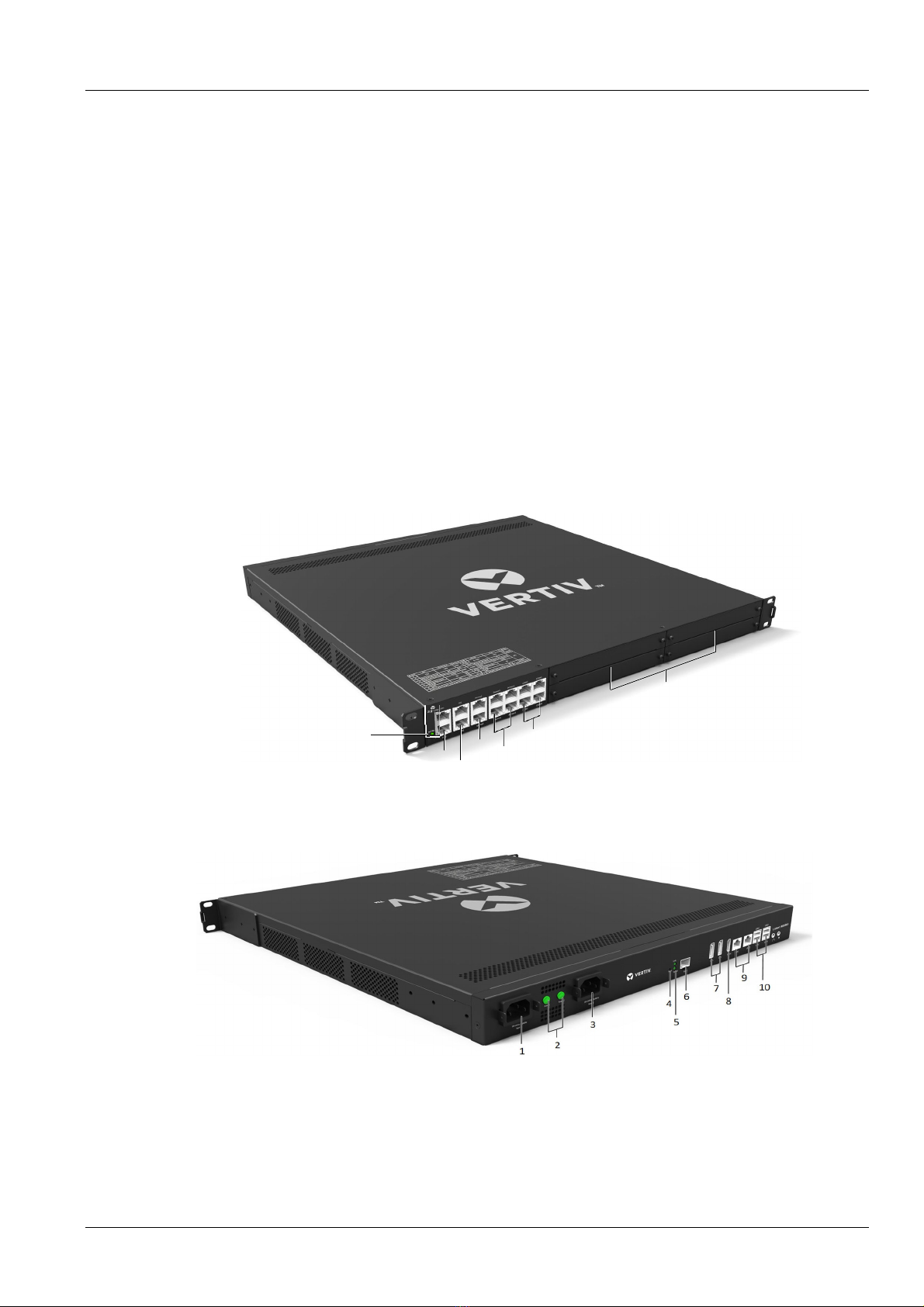
RDU501 Main Unit..................................................................................................................................... 1
1.1.2
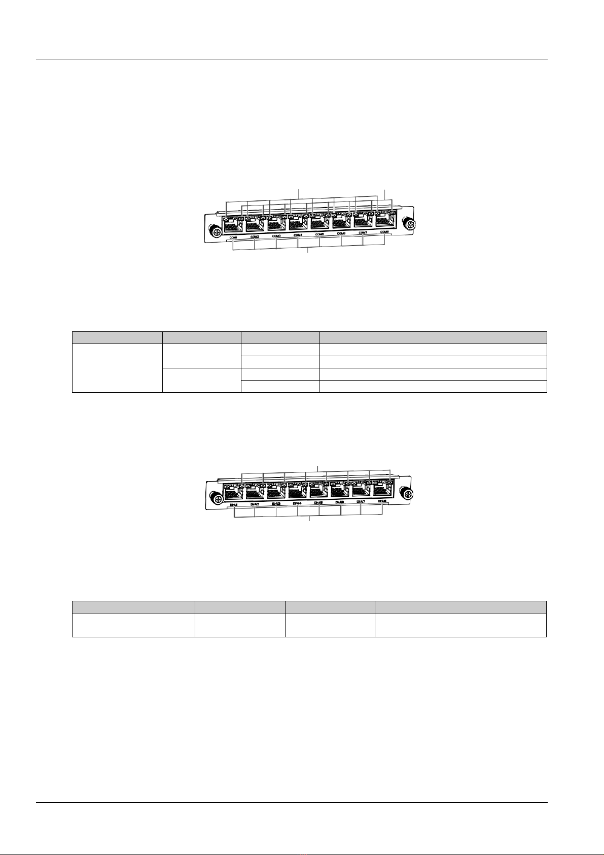
Expansion card.......................................................................................................................................... 4
1.2
Main Functions...................................................................................................................................................... 6
1.3
Technical Specifications ....................................................................................................................................... 7
1.3.1
Environmental Specifications..................................................................................................................... 7
1.3.2
Mechanical Specifications ......................................................................................................................... 7
1.3.3
Performance Specifications ....................................................................................................................... 8
1.3.4
Product Certification .................................................................................................................................. 9
Chapter 2 Hardware Installation ........................................................................................................................................ 10
2.1
Installation Preparation ....................................................................................................................................... 10
2.1.1
Cautions .................................................................................................................................................. 10
2.1.2
Environmental Requirements .................................................................................................................. 10
2.1.3
Space requirements ................................................................................................................................ 10
2.1.4
Installation Tools...................................................................................................................................... 10
2.2
Install RDU501 Main Unit.................................................................................................................................... 11
2.2.1
Mechanical installation............................................................................................................................. 11
2.2.2
Electrical connection................................................................................................................................ 11
2.3
Install Accessories of Expansion Card and Sensor............................................................................................. 12
2.3.1
Install expansion card.............................................................................................................................. 12
2.3.2
Install intelligent sensors.......................................................................................................................... 12
2.3.3
Install physics sensor............................................................................................................................... 13
Chapter 3 Web Interface of RDU501................................................................................................................................. 15
3.1
Login Preparation................................................................................................................................................ 15
3.1.1
Checking IP Address Connectivity........................................................................................................... 15
3.1.2
Checking browser version ....................................................................................................................... 15
3.2
Login RDU501 .................................................................................................................................................... 15
3.2.1
Authorized Startup................................................................................................................................... 15
3.2.2
Login page............................................................................................................................................... 16
3.2.3
Retrieving the password .......................................................................................................................... 16
3.3
RDU501 Main Page ............................................................................................................................................ 17
3.3.1
Power and Environment Overview........................................................................................................... 17
3.3.2
Overview of IT Device.............................................................................................................................. 20
3.3.3
Time calibrating link................................................................................................................................. 21
3.3.4
Release timeout....................................................................................................................................... 21
3.3.5
Logout...................................................................................................................................................... 21
3.3.6
Real-time alarm reminder settings ........................................................................................................... 21