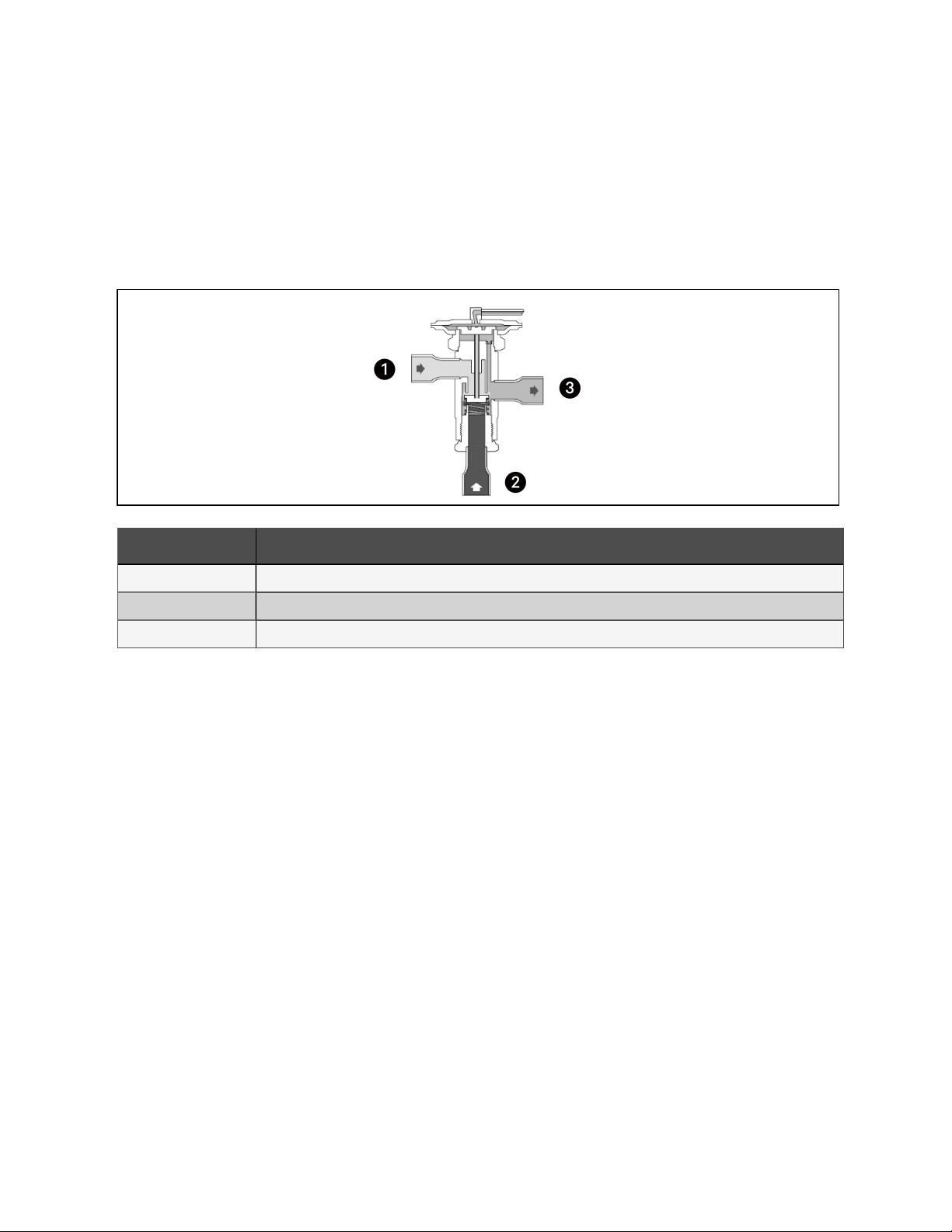
Head Pressure Valve
The head pressure valve is a three-way modulating valve that responds to discharge pressure. When the discharge pressure
falls below a certain value, the discharge port is opened and the discharge gas bypasses the condenser. When the discharge
pressure is high, the discharge port is closed and there is full liquid flow to the condenser.
During the soldering process, care must be taken not to overheat and damage the valve.
Figure 2.2 Structure Diagram of Head Pressure Valve
Item Description
1 Connected with discharge pipe
2 Connected with condenser
3 Connected with receiver
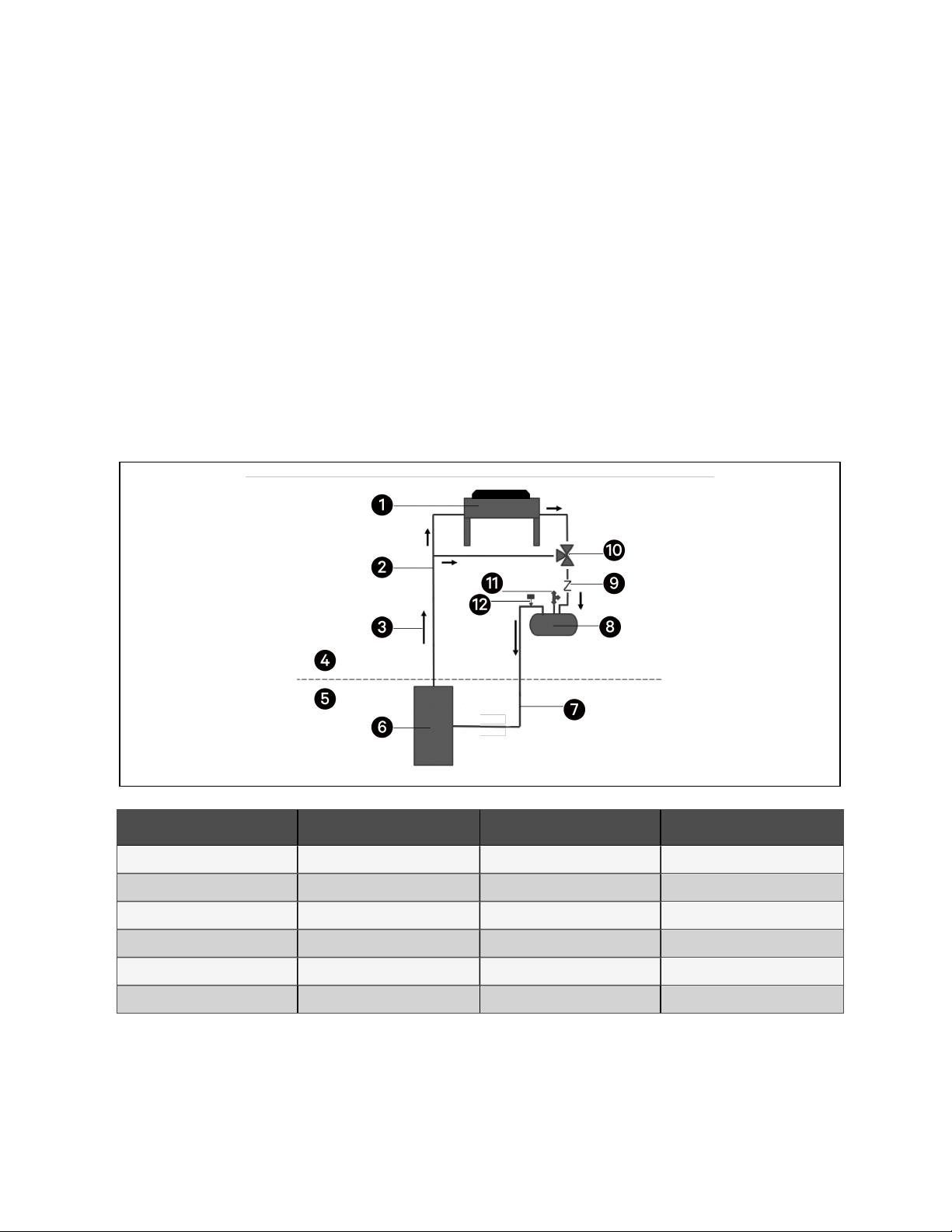
Heater Belt
The receiver is equipped with four heater belts which consume a total power of 300 Watts. The heater belt is controlled by
the pressure of refrigerant in the receiver. When the pressure is lower than 1.4 MPa (203.1 psig), the heater belt will start
heating. When the pressure is higher than 1.9 MPa (275.6 psig), the heater belt will stop heating.
Pressure Switch
Pressure switch controls the heater belt. When the refrigerant pressure in the receiver is lower than 1.4 MPa (203.1 psig), the
pressure switch will be closed and the heater belt will start working. When the refrigerant pressure in the receiver is higher
than 1.9 MPa (275.6 psig), the pressure switch will be opened and the heater belt will stop working.
Check Valve
Check valve is installed between the head pressure valve and the receiver on the liquid line, to prevent the refrigerant from
flowing back to the condenser. The arrow on the valve indicates the direction of the flow and it should point towards the
receiver.
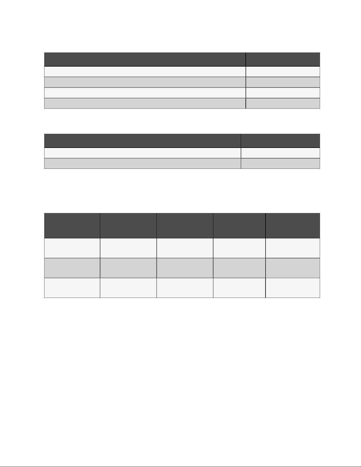
2.3 Accessories
The accessories provided with the condenser are listed in the table below.
2 Nomenclature and Components 5
Vertiv™ Liebert® CRV CCD25 and CCD35 CondensersUser Manual