Vertiv Liebert LSF24-T User manual

Liebert® Air Cooled Condenser
USER MANUAL

Copyright by Vertiv Co. Ltd.
The content in this document is subject to change without notice. All rights, including rights of
translation, reproduced by printing, copying or similar methods, and even of parts, are reserved.
Violators will be liable for damages. All rights, including rights deriving from patent license or
registration of a utility model or design, are reserved. No part of this document may be
reproduced or transmitted in any form or by any means without the prior written consent of
Vertiv Co. Ltd.
Notice
The purchased products, services, and features are stipulated by the contract made between
Vertiv Co., and the customer. All or part of the products, services, and features described in this
document may not be within the purchasing scope or the usage scope. Unless otherwise
specified in the contract, all statements, information, and recommendations in this document
are provided "AS IS" without warranties, guarantees or representations of any kind, either
express or implied. The information in this document is subject to change without notice. Every
effort has been made in the preparation of this document to ensure the accuracy of the
contents, but all statements, information, and recommendations in this document do not
constitute a warranty of any kind, express or implied.
Vertiv Co., Ltd.
•China
Website:www.vertivco.com
E-mail: support@Vertivco.com
Customer service hotline: 4008876510
•Asia Pacific
Homepage: www.vertivco.com
E-mail: overseas.suppor[email protected]
For Technical Support, users may contact the nearest Vertiv Co. local sales office or service
center.

Purpose of the Document
This document applies to the Liebert LSF Air Cooled Condenser used in precision air
conditioners and cooling solutions which maintain an optimal environmental control for
technological ecosystems at minimal operating costs. This document gives an overview of the
technical specifications and parameters. The figures used in this document are for reference
only.
Styling used in this Guide
The styles used in the manual will be defined as mentioned in the following table:
Situation Description
Warning/Danger/Caution
The
Warning/Danger/Caution
note indicates a hazardous or
potentially harmful situation that can result in death or injury. It
also indicates instructions that need to be ad
hered to, failing
which may result in danger and safety issues thereby having an
adverse effect on the reliability of the device and security. Even
for practices not related to physical injury, the content under the
Warning heading is used for precautions which need to be taken
which, otherwise, could result in equipment damage,
performance degradation, or interruption in service.
Note
The
Note
section indicates additional and useful information. It
also calls attention to best practices and industry-best protocols
that are standardized and help make maximum utilization of the
resources at hand. Helpful information related to the product
also comes under the Note heading, helping the users with the
definitions, concepts, and terminologies used in the manual.
Version History
BOM Revision Change
31012725 V1.3 --

TABLE OF CONTENTS
Chapter 1 Overview ............................................................................................1
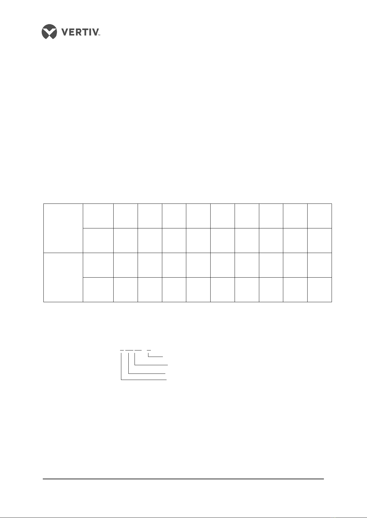
1.1 Classification And Models.....................................................................................................................................1
1.2 Model Description.................................................................................................................................................1
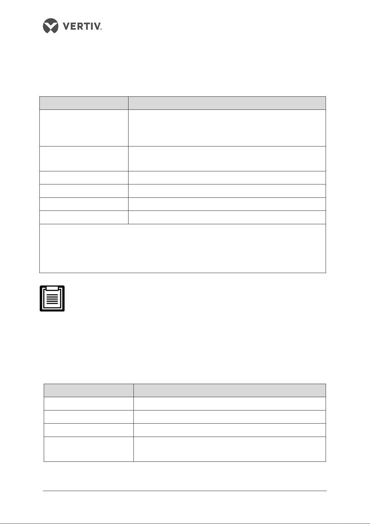
1.3 Main Components .................................................................................................................................................2
1.4 Technical Parameters...........................................................................................................................................3
1.4.1 Mechanical Parameters.............................................................................................................................3
1.4.2 Mounting Base Dimensions.......................................................................................................................4
1.4.3 Parameters of Operating Environment......................................................................................................6
1.4.4 Parameters Of Storage Environment.........................................................................................................6
Chapter 2 Installation ....................................................................................... 7
2.1 Moving, Unpacking And Inspection .....................................................................................................................7
2.2 Installation Notes .................................................................................................................................................8
2.3 Space Requirements ............................................................................................................................................9
2.4 Installation Procedures......................................................................................................................................10
Chapter 3 Application of Fan Speed Controller ...........................................13
3.1 Wiring Terminals................................................................................................................................................. 13
3.2 HMI .....................................................................................................................................................................14
3.3 Operation Description Of HMI ...........................................................................................................................17
3.3.1 Initial Interface.........................................................................................................................................17
3.3.2 Main Menu Interface................................................................................................................................17
Chapter 4 Maintenance and Troubleshooting ............................................24
4.1 Maintenance .......................................................................................................................................................24
4.2 Troubleshooting.................................................................................................................................................26
Appendix Circuit Diagram...........................................................................28

Vertiv I Liebert Air Cooled Condenser I User Manual 1
Chapter 1 Overview
This chapter introduces the classification and models, model description, main components
and technical parameters of the Liebert condenser (condenser for short).
1.1 Classification And Models
The condenser is classified into two types: single circuit and dual circuit. The single circuit has
a set of discharge/liquid pipe to match the single refrigeration system of indoor unit. The dual
circuit has two sets of discharge/liquid pipes to match the two separate refrigeration systems
of indoor unit.
The condenser is available in 17 models. The classification and models are listed in Table 1-1.
Table 1-1 Condenser models
R22/R407C
refrigeration
Single
circuit
LSF24
-T
LSF32-
T
LSF38
-T
LSF42
-T
LSF52-
T
LSF62
-T
LSF70
-T
LSF76
-T
LSF85
-T
Dual
circuit
LDF42
-T
LDF52
-T
LDF62
-T
LDF70
-T
LDF76
-T
LDF85
-T
R410A
refrigeration
Single
circuit
LSF24
-R3
LSF32-
R3
LSF38
-R3
LSF42
-R3
LSF52-
R3
LSF62
-R3
LSF70
-R3
LSF76
-R3
LSF85
-R3
Dual
circuit
LDF42
-R3
LDF52
-R3
LDF62
-R3
LDF70
-R3
LDF76
-R3
LDF85
-R3
1.2 Model Description
Taking LSF62 for example, the model description of the condenser is shown in Figure 1-1.
LSF 62 -T
Liebert
SF: single circuit with fan speed controller
DF: dual circuit with fan speed controller
Model code
-T R22/R407C System
-R3 R410A system
Figure 1-1 Model description

Vertiv I Liebert Air Cooled Condenser I User Manual 2
1.3 Main Components
The main components of the condenser include the heat exchanger, fan, fan speed controller
and pressure sensor. The heat exchanger is inside the condenser, and the appearance and
position of other components are shown in Figure 1-2 and Figure 1-3.
Fan
Figure 1-2 Condenser (single fan, single circuit)
Fans
Isolation switch
Electrical control box (with a fan speed
controller inside)
Pressure sensors
Figure 1-3 Condenser (double fans, dual circuit)
Electrical control box (with a fan speed
controller inside)
Isolation switch
Pressure sensors

Vertiv I Liebert Air Cooled Condenser I User Manual 3
1.4 Technical Parameters
1.4.1 Mechanical Parameters
The condenser structure is shown in Figure 1-4. The mechanical parameters of each model are
listed in Table 1-2.
W
H
L
L
H
Front view Side view
Figure 1-4 Structure (double fans) (unit: mm)
Table 1-2 Mechanical parameters
Model Weight (kg)
Fan diameter
(mm)
Fan number
Dimension (mm)
L H W
LSF24 105 710 1 1384 990 689
LSF32 110 710 1 1384 990 689
LSF38 120 800 1 1384 990 695
LSF42 130 800 1 1584 1273 695
LSF52 140 800 1 1584 1273 695
LSF62 150 710 2 1884 1273 689
LSF70 150 710 2 1884 1273 689
LSF76 220 800 2 2384 1273 695
LSF85 230 800 2 2384 1273 695
LDF42 130 800 1 1584 1273 695
LDF52 140 800 1 1584 1273 695
LDF62 160 710 2 2084 1273 689
LDF70 160 710 2 2084 1273 689
LDF76 220 800 2 2384 1273 695
LDF85 230 800 2 2384 1273 695

Vertiv I Liebert Air Cooled Condenser I User Manual 4
1.4.2 Mounting Base Dimensions
Mounting base dimensions for horizontal installation
The mounting base figure for horizontal installation is shown in Figure 1-5, and the specific
mounting base dimensions of each model are listed in Table 1-3.
DD
L'
D
H'
D
Amplified part figure
D
D
Installation holes
(8 holes in total )
Figure 1-5 Mounting base figure for horizontal installation (unit: mm)
Table 1-3 Mounting base dimensions for horizontal installation (unit: mm)
Model Dimension (L' × H' × D) Model Dimension (L' × H' × D)
LSF24 1126 × 837 × 53 LSF85 2126 × 1120 × 53
LSF32 1126 × 837 × 53 LDF42 1326 × 1120 × 53
LSF38 1126 × 837 × 53 LDF52 1326 × 1120 × 53
LSF42 1326 × 1120 × 53 LDF62 1826 × 1120 × 53
LSF52 1326 × 1120 × 53 LDF70 1826 × 1120 × 53
LSF62 1626 × 1120 × 53 LDF76 2126 × 1120 × 53
LSF70 1626 × 1120 × 53 LDF85 2126 × 1120 × 53
LSF76 2126 x 1120 x 53
The installation holes are long and flat holes. It is recommended to use M10 × 20
bolts to fix the mounting base.

Vertiv I Liebert Air Cooled Condenser I User Manual 5
Mounting base dimensions for vertical installation
The mounting base figure for vertical installation is shown in Figure 1-6, and the specific
mounting base dimensions of each model are listed in Table 1-4.
250 102
452
490
a2020
Figure 1-6 Mounting base figure for vertical installation (top view) (unit: mm)
Table 1-4 Mounting base dimensions for vertical installation (unit: mm)
Model Dimension ‘a’
LSF24, LDF32, LSF38 1280
LSF42, LDF42, LSF52, LDF52 1480
LSF62, LSF70 1780
LDF62, LDF70 1980
LSF76, LDF76, LSF85, LDF85 2280
1.The installation holes are long and flat holes. It is recommended to use M10 × 20
bolts to fix the mounting base.
2. The upper condenser must be installed on a rack during vertical installation, and
the cushion pads should be installed between the condenser and the rack for
reducing vibration. It is prohibited to stack two condensers through bolt
connection.

Vertiv I Liebert Air Cooled Condenser I User Manual 6
1.4.3 Parameters of Operating Environment
Refer to Table 1-5 for parameters of operating environment.
Table 1-5 Parameters of operating environment
Item Requirement
Installation position
The standard equivalent distance between the indoor unit and the condenser
is 30m. Vertical difference* ∆H: -5m ≤ ∆H ≤ 20m. Installation mode: horizontal
or vertical mode
Ambient temperature
Outdoor temperature: -20°C ~ +45°C. Low temperature accessories are
required if the temperature is between -35°C and -20°C
Ambient relative humidity Outdoor humidity: 5%RH ~ 95%RH
Operation power 400V ± 10%, 50/60Hz
Altitude ≤ 1000m. Derating is required if the altitude exceeds 1000m
Protection level Electrical control box: IP55; unit: IP20; fan motor: IP54
Note*:
Condenser fins have a corrosion resistant coating designed to provide maximum life expectancy for the heat
exchanger and protect the aluminium fins from harsh environments. The high performance coating has been
tested for 2000 hours exposure to a 5% neutral salt spray test in accordance with ASTMB117 without impact to the
coating
When the equivalent distance between the indoor unit and the condenser exceeds
30m, refer Refrigerant Tubing System in Liebert LSF Air Conditioner Technical
Manual for the requirement of the line equivalent length.
1.4.4 Parameters Of Storage Environment
Refer to Table 1-6 for parameters of storage environment.
Table 1-6 Parameters of storage environment
Item Requirement
Storage environment Clean indoor environment with good ventilation and no dust
Ambient temperature -40°C ~ +70°C
Ambient relative humidity 5%RH ~ 85%RH
Storage time
The total storage time should not exceed 6 months. Otherwise, the
performance needs to be re-calibrated

Vertiv I Liebert Air Cooled Condenser I User Manual 7
Chapter 2 Installation
This chapter introduces the moving, unpacking, inspection, installation notes, space
requirements and installation procedures.
2.1 Moving, Unpacking And Inspection
Moving
It is recommended to use the mechanical transport equipment such as a forklift or a crane
when unloading and transferring the condenser closest to the installation site.
When a forklift is used, insert the tines of the forklift shown in Figure 2-1 (taking the single fan
condenser for example).
Forklift
direction
Figure 2-1 Forklift direction
When a crane is used, refer to Figure 2-2 to lift the package (taking the double fans condenser
for example).
When lifting the package, fix the cable by leading it through the slots located at the
bottom of the pallet. Otherwise, the cable may slide during the lifting process, and
the package may fall to the ground, damaging the pipes inside and resulting in
system leakage.

Vertiv I Liebert Air Cooled Condenser I User Manual 8
Figure 2-2 Crane lifting
Unpacking
Remove the timber frame package and foam of the condenser but reserve the protection
cardboard of fins. The protection cardboard of fins and the cushion pad of U tube located at
the end of the condenser should be removed after the condenser is in its installation position.
1. If the condenser is to be placed horizontally, you should complete the installation
of legs while the condenser is located vertically.
2. When moving the condenser by hand, to avoid distortion and system leakage, do
not touch the copper pipes.
Inspection
After the product arrival, you should check the accessories against the packing list. If any parts
are found missing or damaged, please report to the carrier immediately. If any covert damage is
found, please report to the carrier and the distributor immediately.
2.2 Installation Notes
The installation notes of the condenser are as follows:
1. To ensure the heat dissipation capacity, install the condenser in the place with smooth
airflow. Do not install it where the coil of the condenser may be obstructed by dust or snow.
Ensure that there is no steam or waste heat around.
2. If possible, the horizontal installation is recommended to reduce the noise.
3. The condenser should be installed away from the residential areas (≥ 15m).

Vertiv I Liebert Air Cooled Condenser I User Manual 9
4. Be careful not to damage the waterproof layer and observe the local regulations when the
condenser is installed on the roof of the building.
5. Position the condenser higher than the indoor unit to ensure normal oil return.
6. Follow the installation arrows on the condenser for correct installation direction.
2.3 Space Requirements
1. A 4000mm clearance is required around the condenser air outlet.
2. 600mm service spaces are required on the four sides of the condenser.
The condenser needs sufficient installation and service space around the installation place.
The specific space requirements are shown in Figure 2-3 and Figure 2-4.
Figure 2-3 Horizontal installation space requirement (unit: mm)
Figure 2-4 Vertical installation space requirement (unit: mm)
Airflow Airflow
Airflow

Vertiv I Liebert Air Cooled Condenser I User Manual 10
2.4 Installation Procedures
Before commencing installation hot works, release all nitrogen holding charges
from the indoor and outdoor units.
Installing pipelines
1. Protect copper pipes from heat sources. Isolate copper pipes from structures or
other obstacles using rigid supports. Avoid dust, water vapor and irrelevant objects
from entering copper pipes.
2.Use a good quality, silver-based solder for all brazed connections. Use
refrigeration grade copper pipes and fittings throughout the installation. Purge all
pipes with nitrogen during brazing to prevent oxidation.
1. Identify the pipe sizes
Refer to Installing Unit Pipes in Liebert LSF Air Conditioner User Manual for pipe sizes.
2. Identify the condenser installation height
Refer to Installing Unit Pipes in Liebert LSF Air Conditioner User Manual for installation height.
3. Install the pipes
Install the pipes according to local and national codes and standards.
Connecting external power (external power supply of the condenser)
1. Identify the cable specifications
Select the power supply cables and start/stop signal cables of the condenser according to site
conditions, such as the distance between the indoor unit and the condenser.
Table 2-1 Operation current of fan under 400V voltage
Condenser Model FLA (A)
LSF24 1.65
LSF32 1.05
LSF38, LSF42, LSF52, LDF42, LDF52 2.4
LSF62, LSF70, LDF62, LDF70 3.3
LSF76, LSF85, LDF76, LDF85 4.8

Vertiv I Liebert Air Cooled Condenser I User Manual 11
1. It is recommended to use the 20AWG (0.52mm2) cable as the condenser
start/stop signal cable.
2. The (outdoor) air cooled condenser requires a three-phase, neutral and earth
power supply. The indoor unit is the recommended point of connection for this
electrical service and includes a three-pole circuit breaker rated at 16 amps.
3. The cables should not contact hot objects, such as the copper pipe and water
pipe without insulation, to avoid damaging the insulation layers.
4. The cables should be connected in accordance with the local regulations.
2. Connect the cables
Refer Figure 2-5, Figure 2-6 and Circuit Diagram for the connections of external power cables.
Figure 2-5 Connection figure of single fan external power cables (taking LDF42 for example)
Figure 2-6 Connection figure of double fans external power cables (taking LDF62 for example)
1. The external power cables enter the electrical control box through the
waterproof joint of external power cable whose inner diameter is Φ10mm.
2. The compressor signal cables enter the electrical control box through the
waterproof joint of external power cable whose inner diameter is Φ6mm.
3.After connecting the external power cables, apply waterproof sealant treatment
to ensure the good waterproof performance of electrical control box.
Waterproof joint of Compressor signal
Waterproof joint of external power
cables by others
Accessing terminal of
external power
supply (single fan)
Fan speed controller board
Accessing terminal of
external power
supply (double fan)
Waterproof joint of
Compressor signal
Waterproof joint of
external power
cables by others

Vertiv I Liebert Air Cooled Condenser I User Manual 12
4. The phase sequence of three-phase AC input (L1, L2, L3) must be correct.
Otherwise, the fan speed controller will generate the phase loss alarm, and there
will be no AC output.
5. For dual circuit condenser (such as LDF42, LDF52, LDF62, LDF70, LDF76 and
LDF85), the four condenser start/stop signal cables should be paralleled at the
terminal block of indoor unit before connection; for single circuit condenser, the
two condenser start/stop signal cables can be connected directly.
Charging refrigerant and adding cooling oil
Refer to Installing Unit Pipes in Liebert LSF Air Conditioner User Manual for charging
refrigerant and adding cooling oil.

Vertiv I Liebert Air Cooled Condenser I User Manual 13
Chapter 3 Application of Fan Speed Controller
This chapter introduces the use of the fan speed controller, which includes the definitions of
wiring terminals, introduction of human-machine interface (HMI) and operation of HMI. This
chapter is mainly provided for the factory maintenance personnel. It is recommended that
users should not operate the fan speed controller unless necessary.
The configured fan number must be the same as the number of the actual fans, or
else a false alarm will be generated. Refer to Configuration data main menu
interface in 3.3.2 Main Menu Interface for detailed settings.
3.1 Wiring Terminals
The wiring terminals are located on the fan speed controller board (Refer Figure 2-5 and
Figure 2-6). Their distribution is shown in Figure 3-1 and the definitions are listed in Table 3-1.
Refer to Circuit Diagram for detailed connections.
Figure 3-1 Layout of wiring terminals

Vertiv I Liebert Air Cooled Condenser I User Manual 14
Table 3-1 Definitions of wiring terminals
Silk print Definition Definition of pins
J1 AC I/O terminal
PE: protection earth
L1, L2, L3: three-phase AC input
U, V, W: three-phase AC output, which connects
with the power supply terminals
The middle terminal pin without logo is reserved
J3 (HP1)
Input terminal of voltage
pressure sensor 1 (spare)
Pin 1: positive terminal of 5V power
Pin 2: input terminal of 0.5V ~ 4.5V pressure
voltage signal
Pin 3: negative terminal of 5V power
J4 (HP2)
Input terminal of voltage
pressure sensor 2 (spare)
J15 (HP1)
Input terminal of current
pressure sensor 1
Pin 1: positive terminal of 12V power
Pin 2: input terminal of 4mA ~ 20mA pressure
current signal
J14 (HP2)
Input terminal of current
pressure sensor 2
J5 (Out Temp)
Input terminal of ambient
temperature sensor (spare)
Pin 1: input terminal of temperature signal
Pin 2: signal ground
J11 (RS485)
Serial communication interface
(used for maintenance)
Pin 1: RS485+
Pin 2: RS485-
J7 (Fan1Sta)
Detecting terminal of fan 1 over
temperaturestate Pin 1: output terminal of 19Vac signal
Pin 2: return terminal of 19Vac signal
J10 (Fan2Sta) Detecting terminal of fan 2 over
temperature state
J6 (CompSta1)
Detecting terminal of
compressor1 state Pin 1: output terminal of 19Vac signal
Pin 2: return terminal of 19Vac signal
J33 (CompSta2)
Detecting terminal of
compressor2 state
3.2 HMI
The fan speed controller operation and setup is provided through indicators, RS485 serial
communication port, keys and LCD.

Vertiv I Liebert Air Cooled Condenser I User Manual 15
Indicators
There are ten indicators (Refer Figure 3-1) on the fan speed controller board. Refer Table 3-2
for the functions of indicators.
Table 3-2 Functions of indicators
Silk print Definition Color State Function
D97
+5V Power
indicator
Yellow
On
The CPU circuit of fan speed controller
board is supplied with 5V power
Off The fan speed controller board is faulty
D115
+12V Power
indicator
Yellow
On
The fan speed controller board is supplied
with +12V power
Off
The fan speed controller board is faulty
D116
+24V Power
indicator
Yellow
On
The fan speed controller board is supplied
with +24V power
Off
The fan speed controller board is faulty
D139
VCOM Power
indicator
Yellow
On
The fan speed controller board is supplied
with VCOM power
Off
The fan speed controller board is faulty
D156
-5V Power
indicator
Yellow
On
The fan speed controller board is supplied
with -5V power
Off The fan speed controller board is faulty
D114
VCC_BOT Power
indicator
Yellow
On
The fan speed controller board is supplied
with VCC_BOT power
Off
The fan speed controller board is faulty
D99 Run indicator Green
On or off
The fan speed controller board is faulty
Blinking at 2Hz
(slowly)
The fan is not running
Blinking at 5Hz
(quickly)
The fan is running
D164 Alarm indicator Red
On
Fan speed controller detects an
alarm(alarms)
Off
No alarm
D100
RS485 sending
indicator
Green
On RS485 is sending data
Off
No data sending
D101
RS485 receiving
indicator
Green
On
RS485 is receiving data
Off
No data receiving

Vertiv I Liebert Air Cooled Condenser I User Manual 16
RS485 serial communication port
The RS485 serial communication port is a port to connect the computer using factory-defined
protocol. It is used for factory commissioning and maintenance.
Keys and LCD
The keys and LCD, which can realize the functions in Table 3-3, provide the HMIs for
maintenance personnel. Refer to 3.3 Operation Description of HMI for operation of keys and
LCD HMI.
Table 3-3 Function descriptions of keys and LCD
NO. Function Description
1
Query the acquisition data in real
time
The acquisition data include condensing pressure, ambient
temperature, output percentage, the state of fan enable singal
and the state of alarm
2
Query the current alarm data in real
time
The current alarm data include phase loss alarm, PIM over
temperature, fan 1 over temperature, fan 2 over temperature,
fan 1 over temperature locked, fan 2 over temperature locked,
pressure sensor failure, EEPROM read fault alarm, hardware
over current and bus over voltage
3
Query the historical alarm data in
real time
The latest saved 100 historical alarms can be queried
4
Modify the configured parameters in
real time
The configured parameters include running pressure,
pressure controlling range, minimum output frequency,
maximum output frequency, fan number and pressure sensor
type, refrigerant type, jump frequency 1, jump frequency 1
range, jump frequency 2, jump frequency 2 range, jump
frequency 3, jump frequency 3 range, the curve of frequency
control, manual mode, manual mode output frequency; or
resume the default values
The keys and LCD are on the upper right corner of the fan speed controller board, as shown in
Figure 3-1. Their appearance is shown in Figure 3-2.
This manual suits for next models
29
Table of contents
Other Vertiv Heat Pump manuals