Vertiv LIEBERT BATTERY INTERFACE BOX UPSBIBX User manual

1
LIEBERT®BATTERY INTERFACE BOX™: UPSBIBX, UPSBIBN AND
UPSBIBR
Product Specification/Installation Sheet—Liebert EXL™, Liebert EXL™S1, Liebert NX™225-600
and Liebert NXL™
SAVE THESE INSTRUCTIONS
This manual contains important instructions that should be followed during installation of your Liebert Battery Interface Box. The Liebert Battery Interface Box can be
used with the Liebert NXL, Liebert NX 225-600, Liebert EXL and Liebert EXL S1 systems. Read this document thoroughly before working with the DC system. Retain
this manual for use by installing personnel.
This unit complies with the limits for a Class A digital device, pursuant to Part 15 Subpart J of the FCC rules. These limits provide reasonable protection against harmful
interference in a commercial environment. This unit generates, uses and radiates radio frequency energy and, if not installed and used in accordance with this
instruction manual, may cause harmful interference to radio communications. Operation of this unit in a residential area may cause harmful interference that the user
must correct at his own expense.
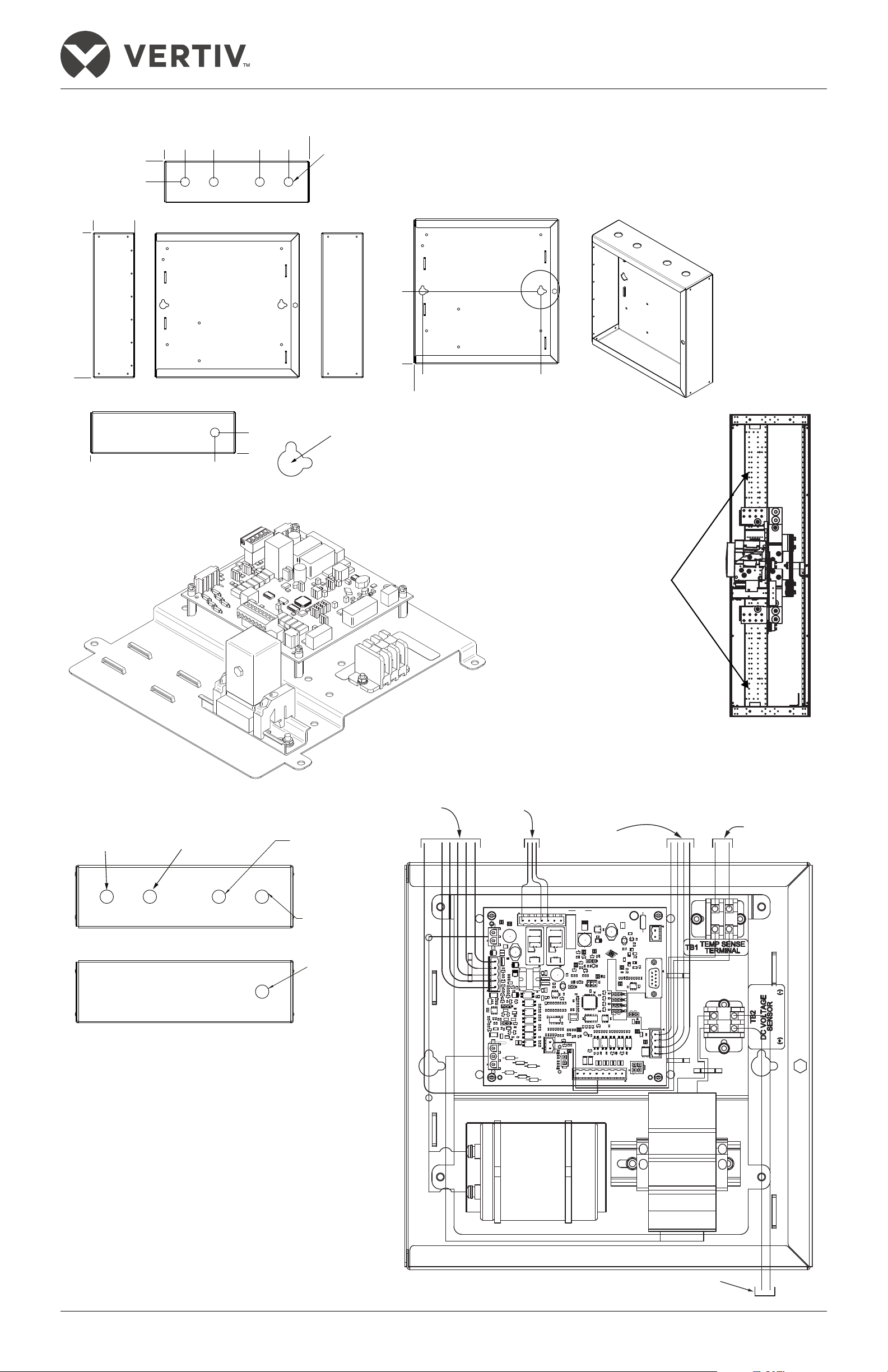
PLACEMENT AND CABLE ENTRY
The Liebert Battery Interface Box should be installed near the DC disconnect. The location should allow access to the box and allow the front door to be opened for
service. Access to the Battery Interface Board (BIB), fuse disconnects and terminal blocks are behind the front door. See Figure 1 for cable entry layout.
UPSBIBX—Separately mounted assembly to interface with a battery breaker, either stand-alone or as part of a battery cabinet.
UPSBIBN—Variation of the UPSBIBX that includes a mounting plate, hardware and wire harness, allowing installation on a Vertiv-supplied MBD and BIS using a
Square D type NW-DC breaker.
UPSBIBR—Separately mounted assembly to interface with a Samsung lithium-ion battery.
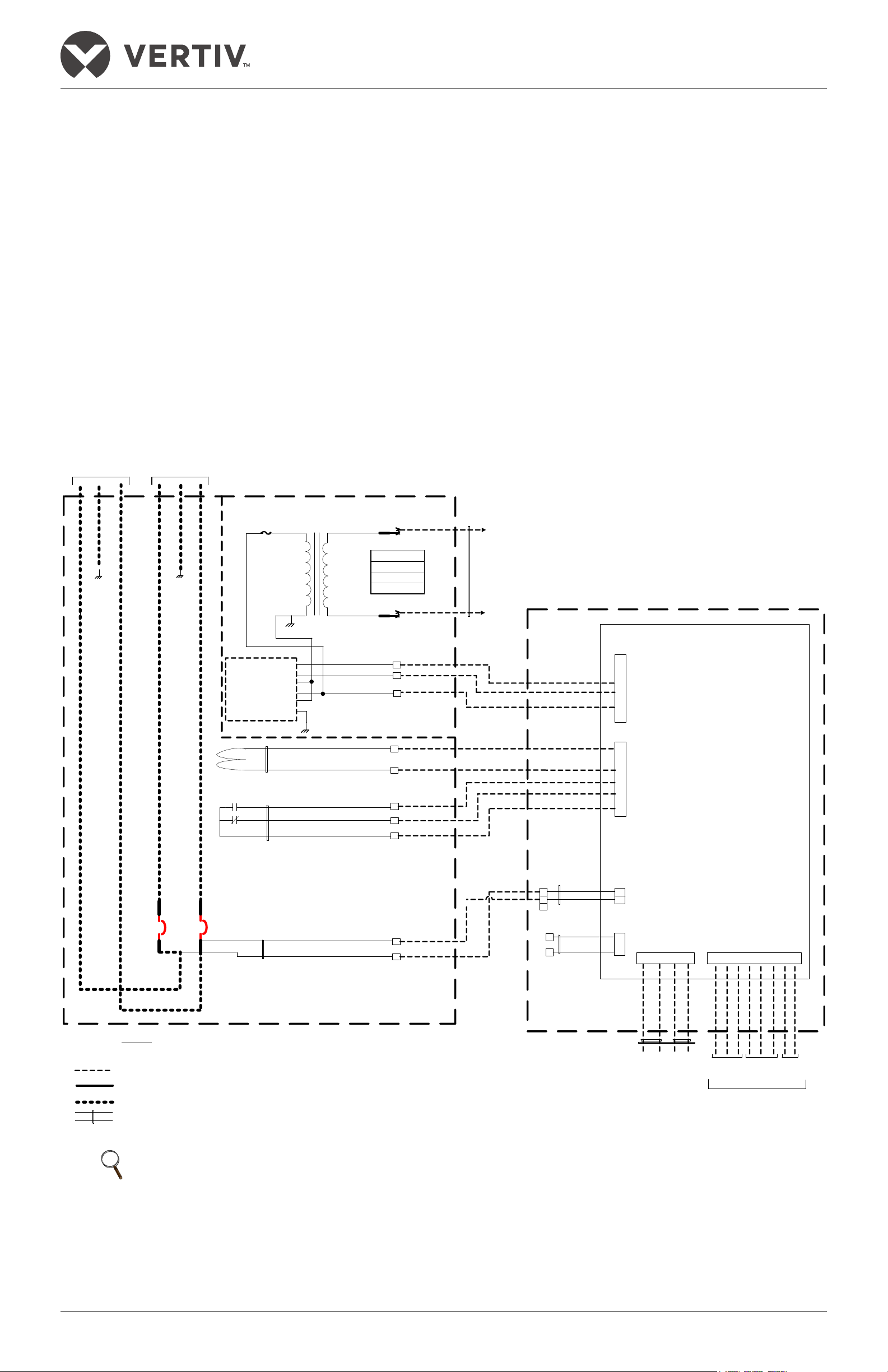
CONTROL CONNECTION
Each Liebert Battery Interface Box contains a Battery Interface Board (BIB). When multiple BIB’s are used, DC systems must have their Battery Interface Board controls
connected in series. The CAN cables must be two twisted pair. Vertiv recommends Belden 9156 or the equivalent; however, the wire size is dependent on the length of
the cable run..
NOTICE
Risk of improper installation. Can cause equipment damage.
During system commissioning, Vertiv Services will set the jumpers on the External Interface Board in the UPS and the BIB. If another DC source is added to the system
after commissioning, it is imperative that Vertiv Services reset the jumpers on the EIB and the BIB.
!
WARNING
Risk of electric shock. Can cause personal injury or death.
The DC terminal voltage connected to this equipment will exceed 400VDC and is potentially lethal. Be constantly aware that the DC system contains
high DC as well as AC voltages. Check for voltage with AC and DC voltmeters before making contact.
Special safety precautions are required for procedures involving handling, installing and maintaining the DC system. Only properly trained and
qualified personnel wearing appropriate personal protective equipment should be involved in installing the Liebert Battery Interface Box or preparing
the system for installation.
Special care must be taken when working with the batteries associated with this equipment. Observe all DC safety precautions before working on or
near the DC system.
The following precautions must be observed when working on this equipment:
• Remove watches, rings and other metal objects.
• Use tools with insulated handles.
• Wear rubber gloves and boots.
• Do not lay tools or metal parts on top of batteries.
• Disconnect charging source prior to connecting or disconnecting DC terminals.
• Determine whether the DC source is grounded. If it is grounded, remove source of ground.
Contact with any part of a grounded DC source can result in electrical shock. The likelihood of such shock will be reduced if such grounds are
removed during installation and maintenance.
!
AVERTISSEMENT
Risque de décharge électrique pouvant causer des blessures graves, voire mortelles.
La tension c.c. à la borne de cet équipement dépasse 400 V c.c. et est potentiellement mortelle. Soyez toujours conscient du fait que le système c.c.
contient des tensions c.c. et c.a. élevées. Vérifiez les tensions avec des voltmètres c.a. et c.c. avant d’établir tout contact.
Des précautions de sécurité spéciales sont requises pour les procédures associées à la manutention, à l’installation et à l'entretien du système c.c.
Seuls des employés qualifiés et dûment formés portant l’équipement de protection personnel approprié peuvent se charger d'installer le boîtier
d’interface pour batterie Liebert ou de préparer le système pour l’installation.
Des précautions particulières doivent être prises lors de travaux touchant les batteries associées à cet équipement. Observez toutes les précautions
de sécurité appropriées lorsque vous travaillez sur à proximité d’une source c.c.
Lorsque vous travaillez avec cet équipement, prenez les précautions suivantes :
• Retirez montre, bagues et tout autre objet métallique.
• Utilisez des outils dont le manche est isolé.
• Portez des gants et des bottes de caoutchouc.
• Ne posez aucun outil ni pièce métallique sur le dessus d’une batterie.
• Déconnectez la source de chargement avant de brancher ou de débrancher les bornes c.c.
• Vérifiez si la source c.c. est mise à la terre. Le cas échéant, éliminez la cause de la mise à la terre.
Le contact avec toute partie d'une source c.c. mise à la terre peut provoquer une décharge électrique. Pour réduire de tels risques d’accident,
débranchez les prises de terre avant de procéder à l’installation ou à l’entretien.
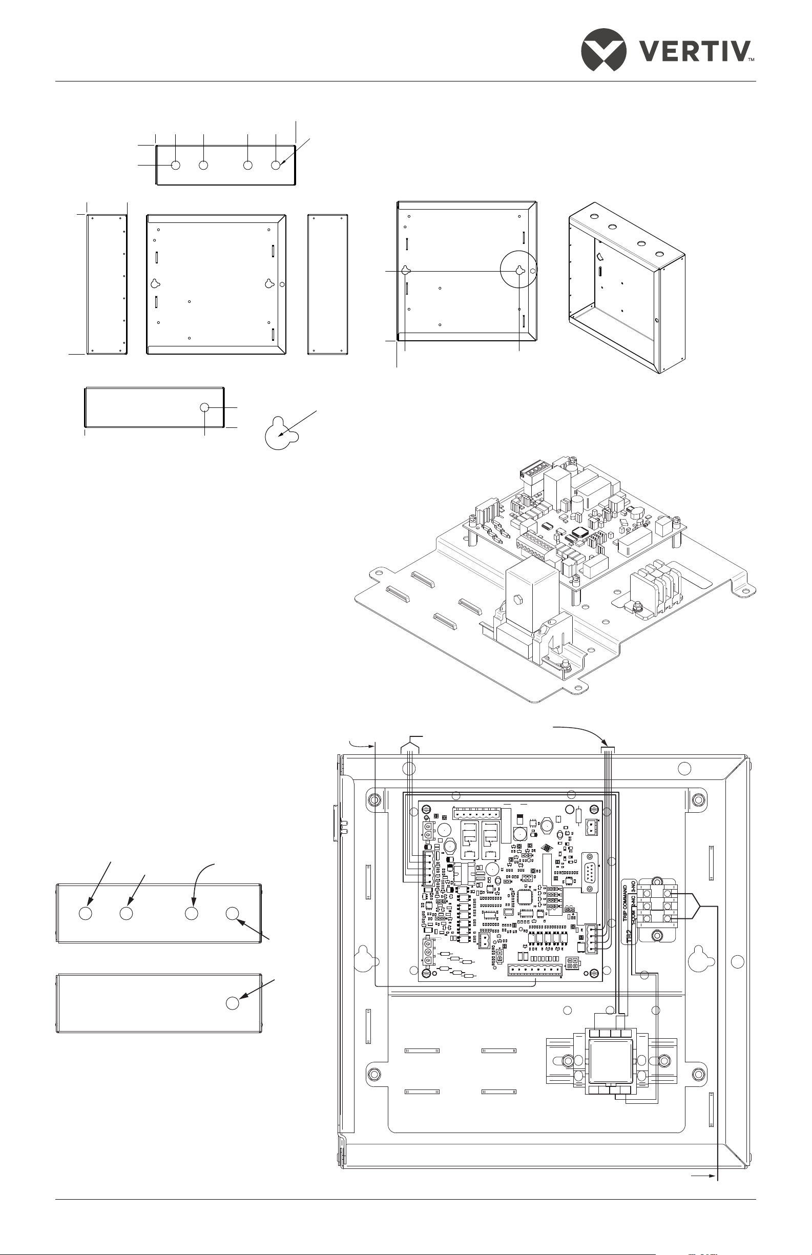
NOTE
Care must be taken to route control cables away from high-voltage cables and busbars.Use recommended knockouts for installing all
cables and use provided tie point to secure, see Figure 2.

2
Figure 1 Dimensions and layout—UPSBIBN and UPSBIBX
Figure 2 Control wiring routing—UPSBIBN and UPSBIBX
NOTE:
1. All dimensions are in inches (mm).
2.Mounting hardware must support the full
weight of units and be appropriate
for the material the box will be attached to.
Dia. .78 (20)
Knockout
4 Places
Mounting Slot Dia.
.25 (6.4); 2 Each
Hole Cutout Dia.
.63 (15.9); 2 Each
A
FRONT
BOTTOM
TOP
LEFT SIDE
0
4.3
(109)
8.3
(211)
10.8
(274)
12.6 (320)
0
12.6
(320)
0
1.8 (46)
1.8
(46)
1.8 (46)
0 10.8 (274)
0
RIGHT SIDE
03.6 (92)
FRONT (MOUNTING)
DETAIL A
0
.7 (19) 11 (280)
0
6.3
(160)
547230
Pg. 3, Rev. 7
Mounting Plate
RIGHT SIDE
MBD12010
The UPSBIBN mounting plate
can be attached to structures on
the right and left side of the
battery breaker. The right side of
the mounting area is shown at
right. Vertiv recommends
making all other cable
connections to the battery
breaker before installing the
UPSBIBN and its mounting plate
in either of the areas indicated
on the right or left side.
Monitoring
UVR/Breaker
Contacts
Leads
Optional
Motor
Operator
Sense
Leads
CAN
Communication
Leads
Optional
Temperature
Sense Leads
Optional DC
Sense Leads
TEMP SENSE
FOR ONLY 1 BOARD IN THE
BOARD IN THE WIRING CHAIN.
JUMPER TO "ON" POSITION
(example jumpers 4+2+1=7)
Each board must have a unique
CAN BUS TERMINATION JUMPER
MUST BE SET TO "ON" POSITION
SET CAN BUS TERMINATION
CAN BUS CHAIN.
FOR THE LAST (FURTHEST AWAY)
SET ALL OTHER BOARDS TO "OFF".
"ON" to indicate number.
number. Set jumpers to
CAN HEALTH
BATT POS
RESISTOR.
TERMINATION
CAN BUS
ENABLE
BARCODE
VOLTAGE
AC HIGH
BAT-
HIGH VOLTAG E
CANL
BATT NEG
CAN TX
CAN BUS
GND
+24V
STATUS
OFF
CLOSED OPEN
NC+
+15V
+ 48V -
DRIVE
+
CAPACITOR
+
ASSY NO. 02-806821- REV
+48V
1
8
MAINT. ALBER
4
CRIT.
ALBER
DANGER!!
BAT+
EPO
CANH +24V
1
OFF
ON
ON
COM-NO+
COIL
-15V
ENABLE
COIL
MTR
CLOSE
POS
NEG
NC
EPO
+
GND
MTRMTR MTR
CRITICAL
NC+
MAINT.
POS
RESET ALARM
COM-
NO+
ALARM
COM-
NC+NO+
REMOTE
NEG
BATTERY
ALARM ALARM
NC+
NO+
NC+
NO+
GND
PS
OK
12
48
1
+
+5V
CB
5
MTR
2
- +
1
ISO
AC1 AC2 AC2
AC1 AC2
7AC2 AC2 1
CLOSE OPEN ENB
P1159
TB1154
R121
P1152
DS14
R124
DS20
R152
R155
R117
TB1150
TB1123
VR1
P1155
R120
TB1158
X5
R131
R22
R30
R43
R50
R46
RT1
R16
R20
R24
R34
R38
TP7
R87
R85
TB1153
DS8
R70
C64
DS5
DS6
DS9
Q3
C40
D15
R84
U19
C11
R18
R21
C18
R40
E8
D20
Q11
R13
R14
C14
R19
C16
R23
R32
R33
R36
R41
TP5
R29
C62
R113
Q1
C22
C29
C26
C31
U12
U17U16
R168
C73
R28
C39
C45
R95
R92
R108
R110
R140
Q18
J8
J5
J4
D10
R60
R68
R72
R76
C44
R80
R104
C55
DS13
D22
U21
C72
R151
R27
R26 Q6
C43
R94
R79
R107 R154
J3
J2
D8 D9
C36
C33
R71
R75
C50
C53
R103
R102R100
R101
R106
C65
U14
Q10
R125
P1160 U9
C25
L5
R136
Q15R134
R150
C3
U1
C10
D7
R91
R123
U20
DS10
R49
R62
C41
D17
C68
R133 R147
Q14
DS7
R31
C24
R52
R57
R63
C49
R98
C59
T1
R10
R54
DS19
R146
C7
D1
R51
Q4
TP6
K1
Q12
R144
R39
TP9
D12
Q2
D13 L6
C6
DS12
TP8
DS11
R56
R3
R6 C69
VR2
C8
L3
R1
TP12
R119
E4
P1153
R118 R132
R88
R89
R122
R86
R37
D5 D6
R42
X4
R116
U3 U7
R115
TP13
U2 U4 U6
DS16
DS17
D14
E3
DS1
R2
TP2
R44
R67
R55
X3
C47
R83
R97
R114
R163
X2
C52
R78
C54
C58
R105
U18
R128 R130 R143
R160
R66
R74
R73
R82
R96
C63 DS18
R142
R139
C38
R69
R81
R77
R93
C57
R161 D24
L2
C46
R112
Q9
L1
R8
U8
J9
R159
R158
R167
R127
Y1
C51
R111
C71
C15
C30
C56
R141
R156
R157
R166
R165
R164
R109 R126
J1
U5
C21 R61
U15
C61 DS15
C37
R65
D19
Q17
D21
C70
R153
C34
C35
R138
U22
Q16
R25
U13
D18
R137
R162
C20 R59
C42
C48
U11
J6
R149
R135
R99
C60
DS4
X1
C32
Q8 R129
TP3
R35
R53
R58
R64
R90
R5
R9
R17
C9
Q7 C67 R148
C2
R4
R7
R12
R15
R11
TP4
Q5
Q13
E7
U10
TP1
R45
R48
C23
D16
C1
D4
J7
R47
K2
C13
R145
P1163
D23
C5
D3
D2 C12
C28
C4 D11
C19 C66
C17
RT2
L4
C27
TP10
TB1151
1158
Knockout for
Optional Temp
Sense Wiring
Knockout
for Optional
DC Sense
Leads,
Monitoring
Knockout for Breaker Aux
Contacts Leads, UVR
and Monitoring
Knockout for Optional
Motor Operator
Sense Wiring
Knockout for
CAN
Communication
TOP VIEW
BOTTOM VIEW

3
Figure 3 Dimensions and layout UPS BIBR
Figure 4 Control wiring routing—UPSBIBR
NOTE:
1. All dimensions are in inches (mm).
2.Mounting hardware must support the full
weight of units and be appropriate
for the material the box will be attached to.
Dia. .78 (20)
Knockout
4 Places
Mounting Slot Dia.
.25 (6.4); 2 Each
Hole Cutout Dia.
.63 (15.9); 2 Each
A
FRONT
BOTTOM
TOP
LEFT SIDE
0
4.3
(109)
8.3
(211)
10.8
(274)
12.6 (320)
0
12.6
(320)
0
1.8 (46)
1.8
(46)
1.8 (46)
0 10.8 (274)
0
RIGHT SIDE
03.6 (92)
FRONT (MOUNTING)
DETAIL A
0
.7 (19) 11 (280)
0
6.3
(160)
547230
Pg. 3, Rev. 7
Mounting Plate
7812
643
5
P1152
Breaker
Trip Command
TEMP SENSE
FOR ONLY 1 BOARD IN THE
BOARD IN THE WIRING CHAIN.
JUMPER TO "ON" POSITION
(example jumpers 4+2+1=7)
Each board must have a unique
CAN BUS TERMINATION JUMPER
MUST BE SET TO "ON" POSITION
SET CAN BUS TERMINATION
CAN BUS CHAIN.
FOR THE LAST (FURTHEST AWAY)
SET ALL OTHER BOARDS TO "OFF".
"ON" to indicate number.
number. Set jumpers to
CAN HEALTH
BATT POS
RESISTOR.
TERMINATION
CAN BUS
ENABLE
BARCODE
VOLTAGE
AC HIGH
BAT-
HIGH VOLTAG E
CANL
BATT NEG
CAN TX
CAN BUS
GND
+24V
STATUS
OFF
CLOSED OPEN
NC+
+15V
+ 48V -
DRIVE
+
CAPACITOR
+
ASSY NO. 02-806821- REV
+48V
1
8
MAINT. ALBER
4
CRIT.
ALBER
DANGER!!
BAT+
EPO
CANH +24V
1
OFF
ON
ON
COM-NO+
COIL
-15V
ENABLE
COIL
MTR
CLOSE
POS
NEG
NC
EPO
+
GND
MTRMTR MTR
CRITICAL
NC+
MAINT.
POS
RESET ALARM
COM-
NO+
ALARM
COM-
NC+NO+
REMOTE
NEG
BATTERY
ALARM ALARM
NC+
NO+
NC+
NO+
GND
PS
OK
12
48
1
+
+5V
CB
5
MTR
2
- +
1
ISO
AC1
AC2 AC2
AC1
AC2
7
AC2 AC2
1
CLOSE OPEN ENB
P1159
TB1154
R121
P1152
DS14
R124
DS20
R152
R155
R117
TB1150
TB1123
VR1
P1155
R120
TB1158
X5
R131
R22
R30
R43
R50
R46
RT1
R16
R20
R24
R34
R38
TP7
R87
R85
TB1153
DS8
R70
C64
DS5
DS6
DS9
Q3
C40
D15
R84
U19
C11
R18
R21
C18
R40
E8
D20
Q11
R13
R14
C14
R19
C16
R23
R32
R33
R36
R41
TP5
R29
C62
R113
Q1
C22
C29
C26
C31
U12
U17U16
R168
C73
R28
C39
C45
R95
R92
R108
R110
R140
Q18
J8
J5
J4
D10
R60
R68
R72
R76
C44
R80
R104
C55
DS13
D22
U21
C72
R151
R27
R26 Q6
C43
R94
R79
R107 R154
J3
J2
D8 D9
C36
C33
R71
R75
C50
C53
R103
R102R100
R101
R106
C65
U14
Q10
R125
P1160 U9
C25
L5
R136
Q15R134
R150
C3
U1
C10
D7
R91
R123
U20
DS10
R49
R62
C41
D17
C68
R133 R147
Q14
DS7
R31
C24
R52
R57
R63
C49
R98
C59
T1
R10
R54
DS19
R146
C7
D1
R51
Q4
TP6
K1
Q12
R144
R39
TP9
D12
Q2
D13 L6
C6
DS12
TP8
DS11
R56
R3
R6 C69
VR2
C8
L3
R1
TP12
R119
E4
P1153
R118 R132
R88
R89
R122
R86
R37
D5 D6
R42
X4
R116
U3 U7
R115
TP13
U2 U4 U6
DS16
DS17
D14
E3
DS1
R2
TP2
R44
R67
R55
X3
C47
R83
R97
R114
R163
X2
C52
R78
C54
C58
R105
U18
R128 R130 R143
R160
R66
R74
R73
R82
R96
C63 DS18
R142
R139
C38
R69
R81
R77
R93
C57
R161 D24
L2
C46
R112
Q9
L1
R8
U8
J9
R159
R158
R167
R127
Y1
C51
R111
C71
C15
C30
C56
R141
R156
R157
R166
R165
R164
R109 R126
J1
U5
C21 R61
U15
C61 DS15
C37
R65
D19
Q17
D21
C70
R153
C34
C35
R138
U22
Q16
R25
U13
D18
R137
R162
C20 R59
C42
C48
U11
J6
R149
R135
R99
C60
DS4
X1
C32
Q8 R129
TP3
R35
R53
R58
R64
R90
R5
R9
R17
C9
Q7 C67 R148
C2
R4
R7
R12
R15
R11
TP4
Q5
Q13
E7
U10
TP1
R45
R48
C23
D16
C1
D4
J7
R47
K2
C13
R145
P1163
D23
C5
D3
D2 C12
C28
C4 D11
C19 C66
C17
RT2
L4
C27
TP10
TB1151
Breaker Contacts
CAN
Communication
Leads
Monitoring
1158
Not Used
Not Used
Knockout for Breaker Aux
Contacts and Monitoring
Knockout
for Optional
DC Sense
Leads, Trip
BCB
Knockout for
CAN Communication
TOP VIEW
BOTTOM VIEW

4
OPTIONAL EXTERNAL BATTERY ROOM TEMPERATURE SENSOR—UPSBIBX AND UPSBIBN ONLY
Connecting an optional sensor to the BIB to monitor the ambient room temperature will enable the Liebert NXL™and Liebert NX™225-600 to perform temperature
compensation charging. The Liebert EXL™and Liebert EXL S1 can detect overtemperatures with the optional temperature sensor installed and can open the battery
breaker to prevent thermal runaway. The UPS’s both perform temperature compensation charging.
OPTIONAL DC SENSE CONNECTIONS—UPSBIBX AND UPSBIBN ONLY
Connecting the optional DC sense voltage wires will allow the Liebert NXL, Liebert NX 225-600 and Liebert EXL to display the DC source on the UPS HMI. This
connection cannot be used with split-battery bus systems, flywheel systems or any DC system that does not have a valid DC voltage when the DC breaker is open.
If the DC sense wires are connected to the BIB, the DC source cabinet may require field-installed fuse protection; refer to national and local codes to verify. The DC
sense wires must run from the most-positive DC voltage to the most-negative DC voltage.
DC BREAKER UNDERVOLTAGE RELEASE (UVR) CONTACTS—UPSBIBX AND UPSBIBN ONLY
If the DC breaker is used as a Module Battery Disconnect breaker (UPS will have control of the breaker), then the 48V UVR contacts must be run to the BIB.
If the DC breaker is used as a Battery Isolation Switch, then the 48V UVR contacts will not be run to the BIB.
OPTIONAL MOTOR OPERATOR CUSTOMER CONNECTIONS
UPSBIB-X and UPSBIB-N is available only for the Liebert EXL and Liebert NX. The option permits remotely closing the circuit breaker from the UPS.
Figure 5 Motor operator customer connections—UPSBIBX and UPSBIBN only
NOTE
Unless otherwise noted, use copper or aluminum conductors suitable for at least 75°C.
+-
MBD
+-
TB1150 (T Conn)
Battery Interface
Board (BIB)
TB1151 (T Conn)
4
3
2
5
1
TB1153
Optional Battery
Voltage Sense
(540VDC)
+
-
To
UPS
MBD Form C
From
Battery String
Thermistor
(Option )
Notes:
Unless noted otherwise, wiring symbols used are:
Control wiring by others
Copper busbar/ cable landing for power cables
Power wiring by others
Twisted pair control wiring
EG
5
4
2
P1152
1
+
2
-
BIB w/
Enclosure
MBD w/ Enclosure
++
--
+
-
-
+
EG
TB2
HV TB
Red
Black
White
Yellow
Brown
Input Voltage
208V
460V/ 480V
575V/ 600V
H1
FDISC 2
T1
F1
H2X1
X2
From UPS Input
(F53, F54, line-side of CB1)
Use FNQ-R-15 fuses
FDISC 1
Control - Off
Control - On
120/230VAC
120/230VAC
TB2
Motor Operator Parts
Motor Op .
120/230VAC
(Option)
Green
Critical
Alarm
Cont.
CAN L (In)
CAN H (In)
TB1154 (T Conn)
241
Input from TB1154A
(UPS EIB)
+24V (In)
3
Gnd (In)
1
TB1158 (T Conn)
764523
Maint.
Alarm
Cont.
Input from Alber Monitor (Option)
8
Remote
Reset
Control
Contact
UVR Coil
(48VDC)
NO
NC
Com
Com
NC
NO
Neg
Po s
1
2
TB1
Fuse
Block
1
2
3

5
Table 1 Cable groups—UPSBIBX and UPSBIBN
Terminal Designation
Signal Name
Max.
Voltage
Max.
Current
Wire
Range
Max.
Length RemarksFrom To
DC Breaker
Cabinet
TB2-1 DC Voltage - Positive 600VDC 2mA #14-22AWG 10ft.
(3m) Optional
TB2-2 DC Voltage - Negative
TB1150-1 Breaker Aux Comm
24VDC 10mA #14-22AWG 10ft.
(3m)
Pin 2 Shorted to Pin 1 = CB is Open
Pin 3 Shorted to Pin 1 = CB is Closed
TB1150-2 Breaker Aux Open
TB1150-3 Breaker Aux Closed
TB1150-4 Breaker UVR Trip Coil (-) 48VDC 100mA #14-22AWG 10ft.
(3m)
The UVR contacts are required if the DC breaker will be
controlled Module Battery Disconnect (MBD) breaker.
TB1150-5 Breaker UVR Trip Coil (+)
TB1153-1 Temp Sense 5V 10mA #14-22AWG 100ft.
(30.5m)
Optional
Cable must be rated for 600V
TB1153-2 Temp Sense Return
TB1151-2 Motor Op 120/230V Sense
120V/
230V 15A #14-8AWG 100ft.
(30.5m) Optional
Circuit protected by 15A fuse (FNQ-R type) in UPS.
Actual voltage and current to MBD determined by MBD
manufacturer.
TB1151-4 Motor Op Control Off
TB1151-5 Motor Op Control On
UPS - F53-2 Motor Op Power Ph A 480VAC 15A #14AWG 500ft.
(150m)
UPS - F54-2 Motor Op Power Ph C
TB1158-6 MIN NO Minor Alarm NO
30VDC 1A #22AWG 500ft.
(150m)
Maintenance Alarm on UPS Display
TB1158-5 MIN NC Minor Alarm NC Maintenance Alarm on UPS Display
TB1158-4 MIN COM Minor Alarm COM Maintenance Alarm on UPS Display
TB1158-3 MAJ NO Major Alarm NO Critical Alarm on UPS Display
TB1158-2 MAJ NC Major Alarm NC Critical Alarm on UPS Display
TB1158-1 MAJ COM Major Alarm COM Critical Alarm on UPS Display
Previous BIB
Box or UPS
TB1154-1 CAN +24V 24VDC 2A
#18AWG 1000ft.
(300m)
Belden 9156 (2 Twisted Pair) or equal
The maximum length must take into account all
connections of the CAN communication cables in the DC system.
TB1154-2 CAN Common
TB1154-3 CAN Bus High 24VDC 2A
TB1154-4 CAN Bus Low
Table 2 Cable groups—UPSBIBR
Terminal Designation
Signal Name
Max.
Voltage
Max.
Current
Wire
Range
Max.
Length Remarks
From To
TB1-1 MCCB STAT COM MCCB COM
30VDC 1A #22AWG 500ft.
(150m)
—
TB1-2 MCCB STAT NC All MCCB’s Open —
TB1-3 MCCB STAT NO MCCB Closed
#22AWG 500ft.
(150m)
—
TB2-3 Input Trip BCB Input 5VDC 10mA —
TB2-1 Ground Trip BCB COM —
TB1158-6 MIN NO Minor Alarm NO
30VDC 1A #22AWG 500ft.
(150m)
Maintenance Alarm on UPS Display
TB1158-5 MIN NC Minor Alarm NC Maintenance Alarm on UPS Display
TB1158-4 MIN COM Minor Alarm COM Maintenance Alarm on UPS Display
TB1158-3 MAJ NO Major Alarm NO Critical Alarm on UPS Display
TB1158-2 MAJ NC Major Alarm NC Critical Alarm on UPS Display
TB1158-1 MAJ COM Major Alarm COM Critical Alarm on UPS Display
Table 3 Battery Interface Box specifications—UPSBIBX, UPSBIBN and UPSBIBR
Parameter
Values
UPSBIBX/UPSBIBN UPSBIBR
DC Sense Volts, VDC 384-576 —
DC Sense Current, IDC 0.0002A —
CAN Volts, VDC 24V 24V
CAN Maximum Current, IDC 2A 2A
UVR Volts, VDC 48V —
Dry Contacts Volts, VDC (Auxiliary Contacts) 24V 24V
Dry Contacts Volts, VDC (Breaker Aux) 10mA 10mA
Mounting Hardware (supplied by others) Must support 30 lb. (13.6kg) Must support 30 lb. (13.6kg)
UVR Max Cont Current, IDC 100mA —

6
© 2011 Liebert Corporation
All rights reserved throughout the world. Specifications subject to change without
notice.
® Liebert is a registered trademark of Liebert Corporation. All names referred to are
trademarks or registered trademarks of their respective owners.
SL-25515_REV13_02-18
Vertiv
1050 Dearborn Drive
P.O. Box 29186
Columbus, OH 43229
Telephone: 1-800-877-9222
Facsimile: 1-614-841-6022
www.vertivco.com
TECHNICAL SUPPORT / SERVICE
Web Site
www.vertivco.com
Monitoring
liebert.monitoring@vertivco.com
800-222-5877
Outside North America: +00800 1155 4499
Three-Phase UPS & Power Systems
800-543-2378
Outside North America: 614-841-6598
LOCATIONS
United States
1050 Dearborn Drive
P.O. Box 29186
Columbus, OH 43229
Europe
Via Leonardo Da Vinci 8
Zona Industriale Tognana
35028 Piove Di Sacco (PD) Italy
+39 049 9719 111
Fax: +39 049 5841 257
Asia
29/F, The Orient Square Building
F. Ortigas Jr. Road, Ortigas Center
Pasig City 1605
Philippines
+63 2 687 6615
Fax: +63 2 730 9572
This manual suits for next models
2
Table of contents
Other Vertiv Recording Equipment manuals