Vertiv Liebert SiteLink-2E User manual

Liebert® SiteLink-E™
SiteLink-2E, SiteLink-4E, and SiteLink-12E
Installation Manual

Technical Support Site
If you encounter any installation or operational issues with your product, check the pertinent section of
this manual to see if the issue can be resolved by following outlined procedures. Visit
https://www.VertivCo.com/en-us/support/ for additional assistance.

TABLE OF CONTENTS
1 Product Overview 5
2 Installing the Liebert SiteLink-E Module 7
2.1 Preparations for Mounting the Module 7
2.1.1 Choose a Location to Install the Liebert SiteLink-E 7
2.2 Enclosure Diagrams 7
3 Connect Input Power Wiring 11
3.1 Power Wiring 11
3.1.1 Input Power Requirements 11
3.2 Connect Input Power—AC or DC 11
4 Communication and Control Wiring 13
4.1 IGM Communication 13
4.1.1 Wiring IGM Ports 13
4.2 RS-485 and ARC156 Wiring Considerations 14
4.3 Wiring for BACnet/ARC156 Network 15
4.4 Wiring Port S1 16
4.4.1 Wiring Port S1 for RS-485 Network—Four-Wire 16
4.4.2 Wiring Port S1 for RS-485—Two-Wire 17
4.4.3 Wiring Port S1 for RS-232 18
4.5 Wiring a Modem for Half-Router Communication—Port S1 19
5 Specifications 21
Appendices 23
Appendix A: Communication Protocol and Wiring Considerations 23
Vertiv | Liebert® SiteLink-E™ Installation Manual | 3

Vertiv | Liebert® SiteLink-E™ Installation Manual | 4

1 PRODUCT OVERVIEW
The Liebert SiteLink-E™ interface module is a BACnet router that provides the communications link
between Liebert units and other protocols and modules. The Liebert SiteLink-E module communicates
with Liebert equipment such as environmental units, UPSs, frequency converters and power distribution
units.
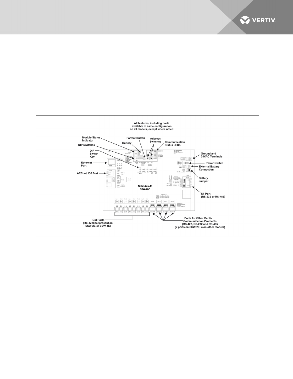
See Figure 1.1 below for port locations. The Vertiv™ ports, Ports1to12, support IGM, Velocity, ASCII, and
Hironet (RS-485). Ports 9to12 may be RS-484 or RS-232.
Figure 1.1 Liebert SiteLink-E layout—power and communication connections, ports and switches
NOTE: This equipment has been tested and found to comply with the limits for a ClassA digital device,
pursuant to Part15 of the FCC Rules. These limits are designed to provide reasonable protection
against harmful interference when the equipment is operated in a commercial environment. This
equipment generates, uses and can radiate radio frequency energy and, if not installed and used in
accordance with the instruction manual, may cause harmful interference to radio communications.
Operation of this equipment in a residential area is likely to cause harmful interference that the user
alone must correct.
Vertiv | Liebert® SiteLink-E™ Installation Manual | 5

Vertiv | Liebert® SiteLink-E™ Installation Manual | 6
This page intentionally left blank.

2 INSTALLING THE LIEBERT SITELINK-E MODULE
The Liebert SiteLink-E module comes in an enclosure for mounting on the wall or floor.
2.1 Preparations for Mounting the Module
2.1.1 Choose a Location to Install the Liebert SiteLink-E
The Liebert SiteLink-E module’s installation location must be easily accessible, within the allowable
cable-run distances for communication wiring and have about 2 in. (51mm) on all sides for wiring and
service.
•Refer to the following drawings in Enclosure Diagrams below:
Enclosure dimensions—overall on the next page
Enclosure dimensions—Wall mount on the next page
Enclosure dimensions—Floor mount on page9
2.2 Enclosure Diagrams
Figure 2.1 Module dimensions, without enclosure
Vertiv | Liebert® SiteLink-E™ Installation Manual | 7

Figure 2.2 Enclosure dimensions—overall
Figure 2.3 Enclosure dimensions—Wall mount
Vertiv | Liebert® SiteLink-E™ Installation Manual | 8

Figure 2.4 Enclosure dimensions—Floor mount
Vertiv | Liebert® SiteLink-E™ Installation Manual | 9

Vertiv | Liebert® SiteLink-E™ Installation Manual | 10
This page intentionally left blank.

3 CONNECT INPUT POWER WIRING
3.1 Power Wiring
WARNING! Risk of electric shock. Can cause injury or death. Disconnect all local and remote
electric power supplies before working within. The Liebert SiteLink-E unit must be connected
by a licensed and qualified electrician only. Ensure that the unit is electrically isolated for the
duration of the connection operation and is secured against unauthorized startup.
CAUTION: Do NOT turn the module On. Turning the module On before it is checked and
approved by a properly trained and qualified specialist may void the warranty. The module
should be turned on by a factory-trained specialist only.
The Liebert SiteLink-E module is a Class 2 device (less than 30VAC, 0.4A). Take appropriate isolation
measures when mounting the Liebert SiteLink-E module in a control panel where non-Class 2 devices
(120VAC or greater) or wiring are present.
Several modules may be powered from the same transformer if:
•the modules have the same polarity
•the transformer’s power rating is at least 20% greater than needed for the modules
For example, if the transformer is rated for 50VA and two modules, each rated at 20VA, are
connected, the power trunk uses a recommended 80% of the transformer’s power (20+20=40).
3.1.1 Input Power Requirements
The Liebert SiteLink-E is available in 50Hz and 60Hz models. The unit has an operating range of 21.6VAC
to 26AVAC. If voltage measured at the module’s power input terminals is outside this range, the module
may not work properly.
3.2 Connect Input Power—AC or DC
Liebert SiteLink-E modules may be powered with either alternating current or direct current within the
operating range of 21.6-26.4 volts. The input power terminals are in the upper right corner of the module
(see Figure 1.1 on page5 for location).
1. Turn the Liebert SiteLink-E module’s power switch Off.
This prevents the module from being powered up before the wiring is completed and the
proper voltage is verified.
2. Make sure the 24VAC power source is Off.
3. Pull the screw terminal connector from the control module’s power terminals labeled
24VAC/DC and Gnd.
4. Connect the transformer wires to the screw terminal connector (see Figure 3.1 on the next
page).
5. Apply power to the power supply.
Vertiv | Liebert® SiteLink-E™ Installation Manual | 11

6. Measure the voltage at the Liebert SiteLink-E’s power input terminals to verify that the voltage
is within the operating range of 21.6-26.4 VAC.
7. Insert the screw terminal connector into the Liebert SiteLink-E’s power terminals.
Figure 3.1 Power connections
Vertiv | Liebert® SiteLink-E™ Installation Manual | 12

4 COMMUNICATION AND CONTROL WIRING
NOTICE
Communication wiring must be performed in accordance with industry standards. All methods,
wiring and connections must comply with local and national codes.
Communication cables must not be kinked or otherwise damaged during installation. Kinked
cables must be replaced.
Communication cables must be properly supported every four feet (1.2m) or less.
4.1 IGM Communication
Liebert SiteLink-E uses the Information Gathering Module Network protocol to communicate to other
Liebert units over the RS-422 protocol. IGM is a point-to-point protocol, where one device connects
directly to another and only those two devices communicate with each other.
NOTE: If shielded cable is used, connect the shield wire to earth (ground) at the Liebert equipment. Do
not ground the shield at the Liebert SiteLink-E.
Liebert SiteLink-E modules have up to 12 IGM ports, depending on the model. The ports are along the
bottom of the module (see Figure 1.1 on page5).
4.1.1 Wiring IGM Ports
1. Connect the IGM wiring to the SiteLink-E IGM ports, using the labels above the ports as a guide
(see Figure 4.1 below).
2. If using a four-wire connection, set the jumpers, located behind the terminals, as required for
the protocol to be implemented. A guide is at the lower right corner of the module’s housing.
Figure 4.1 IGM connections
Vertiv | Liebert® SiteLink-E™ Installation Manual | 13

Figure 4.2 Liebert precision cooling units networked with Liebert SiteLink-E modules
4.2 RS-485 and ARC156 Wiring Considerations
An RS-485 network is intended to be configured as a linear bus with daisy-chained connections (star
topologies are not recommended). Termination in RS-485 and ARC156 setups is usually applied to both
ends of the network (see Wiring Port S1 for RS-485 Network—Four-Wire on page16).
Repeaters often are required when connecting 32 or more RS-485 or ARC156 devices or when using
ARC156 cable segments longer than 2000 feet. Refer to the BMS documentation for information on when
to use repeaters.
To reduce communication and data errors, terminate each end of the network with a resistor whose value
equals the network's characteristic impedance. Some third-party manufacturers provide a built-in resistor
that you enable or disable with a jumper. Make sure that only devices at the end of a network have
termination enabled.
EXAMPLE: If the network’s characteristic impedance is 120 Ohms, terminate the network by
placing a 120 Ohm resistor across the Net+ and Net- connectors of the Liebert SiteLink-E and
a 120 Ohm resistor across the + and - connectors of the furthest third-party device.
Bias must be applied to each RS-485 network segment. To add bias to a network segment, put
the bias jumper in place on the DIAG485 that is in the middle of the segment. You can use
additional DIAG485s with the bias jumper removed to monitor network communication, but
only one DIAG485 may have the bias jumper in place.
Vertiv | Liebert® SiteLink-E™ Installation Manual | 14

4.3 Wiring for BACnet/ARC156 Network
Network Liebert SiteLink-E modules to other Liebert Site Scan modules using the ARCnet port. Set the
baud rate to 156 Kbps for all modules connected to the ARCnet156 network.
NOTE: Use the same polarity throughout the network segment.
1. Be sure the module’s power is Off before beginning to connect wiring for the ARCnet port.
2. Check the network communication wiring for shorts and grounds.
3. Locate the BACnet terminal location in the upper left corner of the Liebert SiteLink-E module
(see Figure 1.1 on page5).
4. Connect the communication wiring to the control module’s screw terminals labeled Net +, Net -
and Shield using the labels near the ARCnet port as a guide. For details, see Figure 4.3 below..
Figure 4.3 BACnet/ARC156 Network port
Vertiv | Liebert® SiteLink-E™ Installation Manual | 15

Figure 4.4 Liebert SiteLink-E modules in ARCnet network
4.4 Wiring Port S1
PortS1 on the Liebert SiteLink-E accommodates these connection types:
•RS-485 four-wire
•RS-485 two-wire
•RS-232
These ports and protocols enable connection to Liebert equipment or to third-party devices, such as a
Building Management System.
4.4.1 Wiring Port S1 for RS-485 Network—Four-Wire
NOTE: Use the same polarity throughout the network segment. The baud rate of the control module's
port must match the baud rate of the third party device. The baud rate may be set in the module driver
properties in Liebert SiteScan™Web. See the Integration Guide for the third-party protocol.
1. Be sure that power to the Liebert SiteLink-E is Off before beginning to connect wiring.
2. Check the communication wiring for shorts and grounds.
3. Wire the Liebert SiteLink-E to the third-party device, using the labels near the Port S1 as a
guide (see Figure 4.5 on page18 for details).
4. Set the RS-232 or RS-485 jumper to RS-485.
5. Set the MS/TP on S1 DIP switch to Enable (On).
6. Set the PTP on S1 DIP switch to Disable (Off).
Vertiv | Liebert® SiteLink-E™ Installation Manual | 16

4.4.2 Wiring Port S1 for RS-485—Two-Wire
For connecting the Liebert SiteLink-E Port S1 to a BMS that uses two-wire RS-485:
•Liebert recommends using shielded, 18-24AWG twisted pair wiring.
•The distance from the Liebert SiteLink-E module to the first RS-485 device depends on the
communications baud rate. This distance seldom should exceed 3,000 ft. (914.4m) at 9600
baud.
1. Be sure that power to the Liebert SiteLink-E is Off before beginning to connect wiring.
2. Check the communication wiring for shorts and grounds.
3. Wire the Liebert SiteLink-E to the third-party device, using the labels near Port S1 as a guide
(see Figure 4.5 on the next page for details).
4. Set the RS-232 or RS-485 jumper to RS-485.
5. Set the MS/TP on S1 DIP switch to Enable (On).
6. Set the PTP on S1 DIP switch to Disable (Off).
Vertiv | Liebert® SiteLink-E™ Installation Manual | 17

Figure 4.5 Port S1 jumpers and DIP switches
4.4.3 Wiring Port S1 for RS-232
NOTE: Use the same polarity throughout the network segment. Use the same baud rate for all control
modules on the network segment.
When connecting the Liebert SiteLink-E Port S1 to a third-party device that uses RS-232:
•Liebert recommends using 18-28AWG wiring.
•Most RS-232 cables are not twisted pair, but twisted-pair wiring is acceptable.
•The distance from the Liebert SiteLink-E to the RS-232 BMS interface should not exceed 50 ft.
(15.2m).
Vertiv | Liebert® SiteLink-E™ Installation Manual | 18

To connect a third-party, RS-232 device to Port S1:
1. Be sure that power to the Liebert SiteLink-E module is Off before beginning to connect wiring.
2. Check the communication wiring for shorts and grounds.
3. Set the RS-232 or RS-485 jumper to RS-232.
Refer to Figure 4.5 on the previous page and to the labels on the Liebert SiteLink-E housing.
4. Connect the communication wiring to the control module’s screw terminals labeled Tx, Rx, and
Signal Ground on Port S1, and jumper the DTR and DCD terminals.
Refer to Figure 4.5 on the previous page and to the labels on the Liebert SiteLink-E housing.
5. Set the MS/TP on S1 DIP switch 4 to Disable (Off).
The DIP switches are at the top of the Liebert SiteLink-E module, near the battery; see Figure
1.1 on page5 for the DIP switch location and Figure 4.5 on the previous page for setting
positions.
6. Set the PTP on S1 DIP switch 5 to Enable (On).
Figure 4.6 RS-232 connection to Port S1
4.5 Wiring a Modem for Half-Router Communication—Port S1
1. Turn Off power to the Liebert SiteLink-E.
2. Connect the modem to Port S1 using a standard modem cable connected to an S2-DB9
adapter, available from Liebert, or a cable made using the wiring diagram in Figure 4.7 below.
3. Set the PTP on S1 DIP switch to Enable (ON).
Refer to Figure 4.5 on the previous page for determining the wiring connections.
Figure 4.7 Fabricated cable for modem in half-router communication
Vertiv | Liebert® SiteLink-E™ Installation Manual | 19

Vertiv | Liebert® SiteLink-E™ Installation Manual | 20
This page intentionally left blank.
This manual suits for next models
2
Table of contents
Other Vertiv Recording Equipment manuals