Vestax PMC-55 User manual

VESTAX CORPORATION
2-37-1Kamiuma,Setagaya-ku,Tokyo154-0011Japan
Phone:03-3412-7011Fax:03-3412-7013
VESTAX America
2750C29thAveSuite.115Hollywood.Fl33020
Phone:303-766-5269Fax:303-766-2196
VESTAX (Europe)Ltd.
18st.ChristophersRoad,Haslemere,SurreyGU271DQEngland.
Phone:(0)1428-653117Fax:(0)1428-661021
OWNER'S MANUAL
55/E/面付け 00.9.12 4:44 PM ページ 16


3
15. Damage Requiring Service-Unplug this product
from the wall outlet and refer servicing to
qualified service personnel under the following
conditions:
a.When the power-supply cord or plug is
damaged.
b. If liquid has been spilled or objects have fallen
into the product.
c. If the product has been exposed to rain or
water.
d. If the product dose not operate normally by
following the operating instructions. Adjust
only those controls that are coverd by the
operating instructions as an improper
adjustment of other, controls may result in
damage and will often require extensive work
by a qualified technician to restore the product
to its normal operation.
e. If the product has been dropped or cabinet has
been damaged.
f. When the product exhibits a distinct change in
perfromance-this indicates need for service.
16. Replacement Parts-When replacement parts are
required, be sure the service technician has used
replacement parts specified by the manufacturer
or have the same characterristics as the original
parts. Unauthorized substitutions may result in
fire, electric shock or other hazards.
17. Safety Check-Upon completion of any service or
repairs to product, ask the service technician to
perfrom sefety checks to determine that the
product is in proper operating condition.
18. Carts and Stands-The appliance should be used
only with a cart stand that is recommended by
manufacturer.
19. An appliance and cart combination should be
moved with care. Quick stops, excessive force,
and uneven surfaces may cause the appliance
and cart combination to overturn.
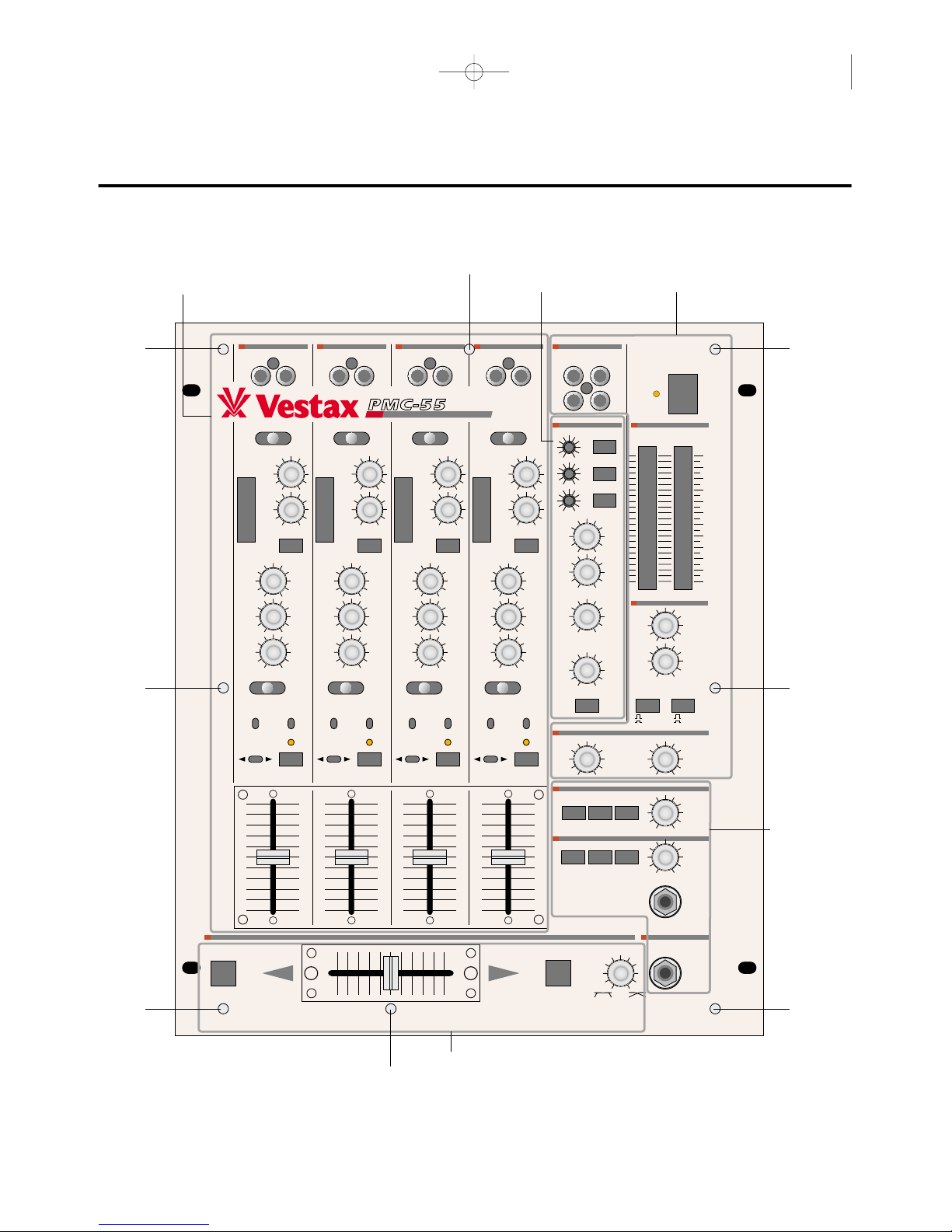
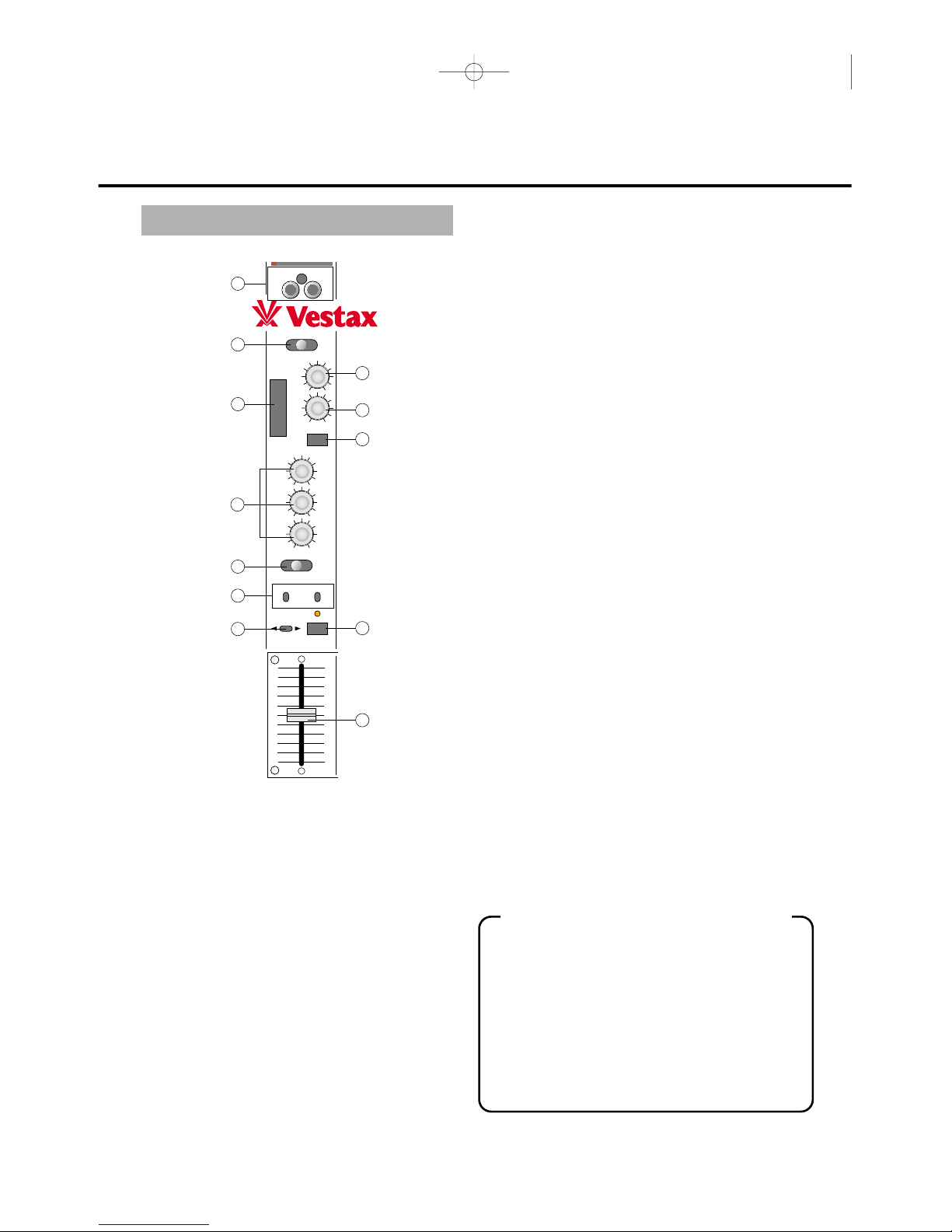
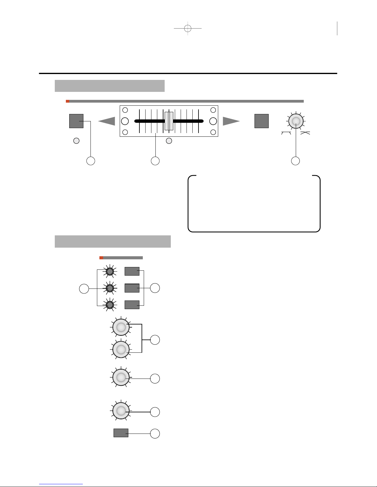
FEATURES
1. A high specification VCA, Voltage Controlled
Amplifier, is utilized in the Crossfader system.
This minimizes noise and wear from the
mechanical parts of the Crossfader. Additionally,
the Crossfader "Curve" can be easily adjusted on
the front panel for change in Mixing styles. At
one extreme is the long running mix and at the
other is the Scratch or Cut mix.
2. Each of the input channels will accept one stereo
phono and two stereo line sources, these are
instanly switchable giving a massive twelve input
capability. Each input channel has a gain control
for the setting of input levels. A level display,
balance control and three band EQ are also
provided on each channel. The separate Mic input
section has its own EQ.
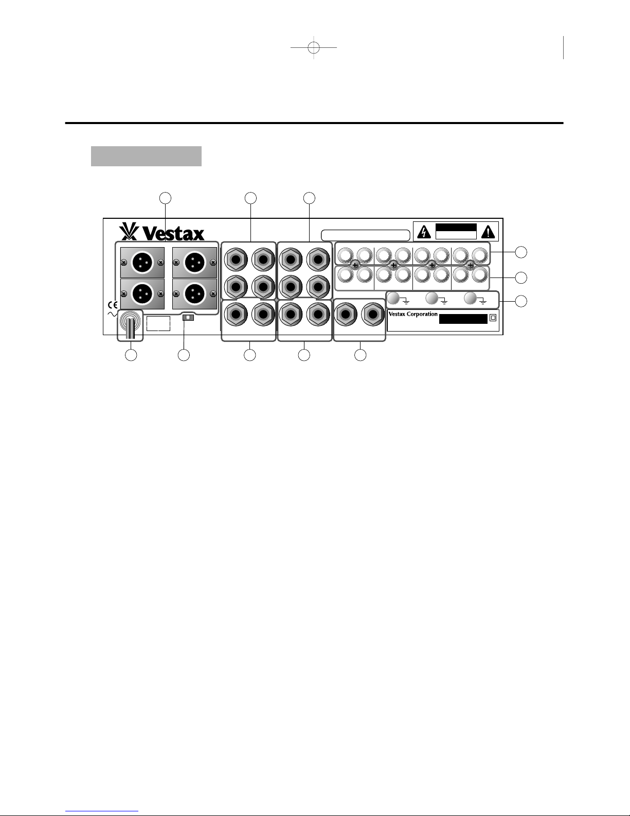
3.One stereo input of each channel can be
connected via the top panel for quick and easy
access. This is particularly useful for "visiting"
DAT players,etc.
4. The stereo Insertion ports are provided on the
front panel. These allow for the easy connection
of outboard effects such as VESTAX DCR-
1200PRO Frequency Separator, Compressor and
Gate machines. And the stereo Master loop is
provided on the top panel also. This allows for
total sound control with Graphic EQ or
Reverberator, etc.
5. The PMC-55 has the most comprehensive output
lineup as well. No less than two separate
Masters(balanced and unbalanced), one DJ Booth
Monitor, one stereo Cue and a Headphones
Monitor makes this mixer the most versatile
"MIXER'S MIXER" available today.
55/E/面付け 00.9.12 4:44 PM ページ 5

4
MAX
LINE 1
PHONO 1 LINE 2
LR
MIN
R
L
PGM 1
+6dB(0dB)
IN
-24dB
PRE
OUT
POST PRE
OUT
POST PRE
OUT
POST PRE
OUT
POST
OUT
A MASTER B
+6dB(0dB)
-24dB
+6dB(0dB)
+6dB(0dB)
+6dB(0dB)
+6dB(0dB)
+6dB(0dB)
+6dB(0dB)
+6dB(0dB)
+6dB(0dB)
+6dB(0dB)
+6dB(0dB)
+3
0
-3
-8
-13
(dB)(
dB)(
dB)(
dB)
(dB)
-24dB
-24dB
-24dB
-24dB
-24dB
-24dB
-24dB
-24dB
-24dB
-24dB
HI
LOW
AUX
MASTER 1
C.F. ASSIGN
CUE
EQ CUT
IN
OUT
MASTER 2
MID
TRIM
BAL
INPUT
EQ EQ EQ EQ
EQ
LINE IN 2
MAX
LINE 3
PHONO 2 LINE 4
LR
MIN
R
L
PGM 2
IN
OUT
A MASTER B
+3
0
-3
-8
-13
HI
LOW
AUX
MASTER 1
C.F. ASSIGN
CUE
EQ CUT
IN
OUT
MASTER 2
MID
TRIM
BAL
INPUT
LINE IN 4
MAX
LINE 5
PHONO 3 LINE 6
LR
MIN
MAXMIN
MAXMIN
R
L
PGM 3
IN
OUT
A MASTER B
+3
0
-3
-8
-13
HI
LOW
AUX
MASTER 1
C.F. ASSIGN
CUE
EQ CUT
IN
OUT
MASTER 2
MID
TRIM
BAL
INPUT
LINE IN 6
MAX
1
+6
+3
+2
+1
0
-1
-2
-4
-7
-10
-15
-20
2
DJ
LINE 7
PHONO 4 LINE 8
LR
L
L
R
R
MIN
R
L
PGM 4
POWER ON
OFF
MASTER LOOP
AUX
MIC LEVEL
MASTER
BOOTH MONITOR
HEAD PHONE MONITOR
DJ MIC IN
IN
OUT
A MASTER B
+3
0
-3
-8
-13
+16dB-16dB
+16dB-16dB
MAXMIN MAXMIN
MAXMIN
MAXMIN
MAXMIN
MAXMIN
HI
HI
LOW
LEVEL
SEND
RCV
MASTER 1
PHONES
TRANSFORMER TRANSFORMER MIC INCF MODE
MASTER 1
MASTER 1
MASTER 2
OFF
ON
IN METER LOOP
MASTER 2
CUE
MASTER
AUXCUE
MASTER 2
TALK OVER
LOW
AUX
MASTER 1
C.F. ASSIGN
CUE
EQ CUT
IN
OUT
MASTER 2
MID
TRIM
BAL
INPUT GAIN
SEND
RCV
ON
LINE IN 8
B
A
PRO FESSIONAL MIXING CONTROLLER
10
9
8
7
6
5
4
3
2
1
0
10
9
8
7
6
5
4
3
2
1
0
10
9
8
7
6
5
4
3
2
1
0
10
9
8
7
6
5
4
3
2
1
0
PROGRAM INPUT
SECTION MICROPHONE
SECTION MASTER
SECTION
MONITOR
SECTION
CROSSFADER
SECTION
(*)
(*)
(*)
(*)
(*)
(*)
(*)
(*)
CONTROL AND FUNCTIONS
55/E/面付け 00.9.12 4:44 PM ページ 8

5
PROGRAM INPUT SECTION
MAX
LINE 1
PHONO 1 LINE 2
LR
MIN
R
L
PGM 1
+6dB(0dB)
IN
-24dB
PRE
OUT
POST
OUT
A MASTER B
+6dB(0dB)
-24dB
+6dB(0dB)
+3
0
-3
-8
-13
(dB)
-24dB
HI
LOW
AUX
MASTER 1
C.F. ASSIGN
CUE
EQ CUT
IN
OUT
MASTER 2
MID
TRIM
BAL
INPUT
EQ
LINE IN 2
10
9
8
7
6
5
4
3
2
1
0
1
3
10
8
9
7
6
11
12
5
4
2
○
5BALANCE CONTROL
Adjusts the stereo balance for each PGM channel.
Can be used for adjusting the unbalanced stereo
image caused by strong Anti-Skating setting.
Clockwise rotation from center position increase
volume of R over L channel. Counter clockwise
rotation increase volume of L channel over R.
○
6EQ CUT SWITCH
Press this switch to bypass EQ secti
on.
○
7EQ (HI, MID, LOW)
Adjusts the HI,MID and LOW frequencies for each
PGM channel. Each band has following
specifications.
HI 8kHz -24dB~ +6dB Shelving type
MID 500Hz -24dB~ +6dB Peaking type
LOW 80Hz -24dB~+6dB Shelving type
○
8AUX ASSIGN SWITCH
Used when sending signal to external effect processor
connected to AUX SEND/RETURN (42).
○
9MASTER OUT ASSIGN 1, 2
Used to send the signal from each program to either
MASTER OUT 1 or 2 (43). MASTER LOOP is
located on MASTER OUT 1.
○
10
CROSSFADER ASSIGN
Used to send the signal from each program to either
the crossfader (A or B) or the master directory. A for
left side of the crossfader, B for right side.
○
11
CUE ASSIGN
Used to send the signal from each program to
monitor section for headphones monitoring. Signal
is sent to CUE OUT (42) too. This allows for
sending signal to external sampling unit connected
to CUE OUT.
○
12
INPUT FADER
Used to adjust the Input level of each program.
Usually set at the 7-8 position. This is a detachable
fader for the ease of replacement. Replace with IF-
50 when It is worn out.
HOW TO REPLACE THE INPUT FADER
●
Remove four screws which hold the fader unit panel.
●Take the unit out with the panel
●Remove a knob and two screws which hold the
fader unit.
●Carefully remove the multi-cable connector from
the fader unit.
●Insert the connector to the new fader unit.
●Replace the knob and the fader unit to the panel
and fix it with screws.
●Replace the fader unit panel and tighten the
screws.
○
1LINE IN 2, 4, 6, 8 (RCA)
Used for line level input. Connect CD player or tape
deck to these jacks. Line level musical instruments
with stereo outputs such as rhythm machine or
sampler are also good for LINE IN. And they are
located on the top panel for quick and easy access.
This is particularly useful for "visiting" equipment.
○
2INPUT SELECTOR
Used to select the input (two LINE or one PHONO)
to be sent to each PGM channel.
○
3INPUT LEVEL METER
The LED level meters indicate the input signal level
of each PGM channel.
○
4GAIN CONTROL
Adjusts the input level of each channel. Set INPUT
FADER (12) to 7-8 position, adjust GAIN so that
INPUT LEVEL METER(3) shows about 0dB.
55/E/面付け 00.9.12 4:44 PM ページ 9

6
CROSSFADER SECTION
MICROPHONE SECTION
TRANSFORMER TRANSFORMER CF MODE
B
A
14 13 15
○
13
CROSS FADER
Mixes the signal assignes by CROSSFADER
ASSIGN(10) to A side of the crossfader and B side.
When the crossfader is set in the center position,
both A and B can be heard. This is a detachable
fader for ease of replacement with CF-50 when it is
worn out.
○
14
TRANSFORMER SWITCH
With the crossfader moved to either right or left, the
opposite program can be heard instantly by pressing
the opposite⑳transformer button.
○
15
CF MODE VOLUME
Adjust the crossfader curve. Clockwise rotation give a
gentle crossfade good for long running mixes. Counter
clockwise rotation gives a steep crossfade good for
scratching and cutting.
○
16
MIC GAIN
Adjusts the input level from each microphone input.
○
17
MIC SELECTOR
Used to select the microphones to be Master section.
○
18
MIC EQ (HI,LOW)
Adjusts the HI and LOW frequencies for all
microphones input.
○
19
MIC LEVEL
Adjusts the input level from all microphones input.
○
20
TALK OVER LEVEL
When TALK OVER SWITCH◯
21
is depressed, the
level of all sources excluding the microphone input
are reduced. Reduction level can be adjusted by this
control. Clockwise rotation gives a large reduction
level.
○
21
TALK OVER SWITCH
When this switch is depressed, the level of all
sources excluding the microphone input are reduced.
HOW TO REPLACE THE CROSS FADER
●
Remove a knob and four screws which hold the fader
unit.
●Take the unit out.
●Carefully remove the multi-cable connector from
the fader unit.
●Insert the connector to the new fader unit.
●Replace the knob and the fader unit and fix it with
screws.
EQ
MAXMIN
MAXMIN
1
2
DJ
MIC
+16dB-16dB
+16dB-16dB
HI
LOW
LEVEL
IN
TALK OVER
GAIN ON
17
18
16
19
20
21
55/E/面付け 00.9.12 4:44 PM ページ 12

7
MASTER SECTION
○
22
MASTER LOOP (RCA)
This loop(send/return) is located on MASTER OUT
1 (43) before output jack. It is useful for total sound
control with Graphic EQ or Reverberator,etc.
○
23
POWER SWITCH
LED located on the top panel is lit when on.
○
24
OUTPUT LEVEL METER
The LED level meters indicate the signal level of
MASTER OUT 1 or 2 (43).
○
25
AUX SEND LEVEL
Used to adjust send level from AUX SEND (41).
The signal is selected by AUX ASSIGN SWITCH
(8).
○
26
AUX RETURN LEVEL
Used to adjust return level to AUX RETURN (41).
This AUX RETURN can be used as the sub line
input.
○
27
METER ASSIGN
Select either MASTER OUT 1 or 2 indicated by
OUTPUT LEVEL METER (25).
○
28
LOOP SWITCH
Used when sending signal to external effect
processor connected to MASTER LOOP (22).
○
29
MASTER OUT LEVEL 1, 2
Used to adjust the output level from MASTER OUT
1 and 2 (43).
(dB)
+6
+3
+2
+1
0
-1
-2
-4
-7
-10
-15
-20
L
L
R
R
POWER ON
OFF
MASTER LOOP
AUX
LEVEL
MASTER
MAXMIN MAXMIN
MAXMIN
MAXMIN
SEND
RCV
MASTER 1
MASTER 1
MASTER 2
OFF
ON
METER LOOP
MASTER 2
SEND
RCV
23
22
2827
24
25
29
26
55/E/面付け 00.9.12 4:44 PM ページ 13

8
MONITOR SECTION
FRONT PANEL
○
30
BOOTH MONITOR SELECTOR
Select either MASTER OUT 1,2 (43) or CUE
ASSIGN (11) for monitoring by boothout.
○
31
BOOTH MONITOR LEVEL
Used to adjust the output level from BOOTH OUT
(44).
○
32
HEADPHONES MONITOR SELECTOR
Select either CUE OUT (42), MASTER OUT (43) or
AUX SEND (41) for monitoring by headphones.
○
33
HEADPHONES LEVEL
Adjusting the headphones output level.
○
34
HEADPHONES JACK
When listening with stereo headphones, connect
them to this jack. This features stereo cue system.
○
35
DJ MIC JACK
Input jack for connecting a DJ microphone.
○
36
PROGRAM SEND/RETURN (RCA)
They are stereo channel insertion ports allow for the
easy connection of outboard effects.
BOOTH MONITOR
HEAD PHONE MONITOR
DJ MIC IN
MAXMIN
MAXMIN
PHONES
MIC IN
MASTER 1 MASTER 2
CUE
MASTER
AUXCUE
31
30
33
34
35
32
RCN
SEND
RCN
SEND
RCN
SEND
RL
PGM1
RL
PGM2
RL
PGM3
PGM I/O
RL
PGM4
36
55/E/面付け 00.9.12 4:44 PM ページ 14

9
REAR PANEL
○
37
LINE IN 1, 3, 5, 7 (RCA)
They work the same as LINE IN 2, 4, 6, 8 (1).
○
38
PHONO IN 1, 2, 3, 4 (RCA)
Connects turntable output equipped with MM type
pickup cartridge. If MC type cartridge is used, a pre-
amp is required.
○
39
GROUND TERMINAL
Connects to ground lead of the turntable. This helps
to reduce noise and hum.
○
40
MIC 1, 2 (1/4" Phone)
Input jack for connecting the microphones.
○
41
AUX SEND/RETURN (1/4" Phone)
Connects to outboard effects such as Delay
machine. AUX SEND is located on pre-input fader.
○
42
CUE OUT (1/4" Phone)
When CUE ASSIGN(11) is depressed,the signal
comes out from this jack. It can be used for
sampling source output.
○
43
MASTER OUT 1, 2
(1/4" Phone, Unbalanced)
Connects to the input of power amplifier. These
jacks are Phone type for consumer applications. This
mixer has two pairs of MASTER OUT. And each
output level can be set separately. This means that
MASTER OUT (43) can be used for main output and
sub. For example, one for hall, the other for entrance.
○
44
BOOTH OUT (1/4" Phone)
This can be used for DJ booth monitor. Same signal
as HEADPHONES OUT comes out.
○
45
MASTER OUT 1, 2 (XLR, Balanced)
Connects to the input of power amplifier. These
connectors are XLR type for professional audio
applications. They works the same as Unbalanced
MASTER OUT 1, 2 (43). Pin No.3 for HOT.
○
46
AC POWER CABLE
Connects the plug to AC outlet on the wall.
○
47
BALANCE OUT LEVEL SWITCH
Used to select the output level of the MASTER
OUT 1.2.
PMC-55
50 / 60Hz 20W
AC100V
MADE IN JAPAN
SERIAL NO.
CAUTON
RISK OF ELECTRIC
SHOCK. DO NOT OPEN
WARNING;SHOCK HAZARD-DO NOT OPEN.
AVIS;RISQUE DE CHOC ELELCTRIQUE -NE PAS OUVRIR.
GND GND GND
LINE 1
PHONO 1
LINE 3
PHONO 2
LINE 5
PHONO 3
RLRLRLRL
R
PIN 1 GND
PIN 2 HOT
PIN 3 COLD
L
RL
RLRL
LINE 7MASTER 1
MASTER 1
MASTER 2
BAL OUT LEVEL
-20 -10 0(dB)
AUX SEND
MASTER 2
AUX RTN
BOOTH OUT
CUE OUT
PHONO 4
MIC 2 MIC 1
PROFESSIONAL MIXING CONTROLLER
46 44
43 4145
42 4047
39
38
37
55/E/面付け 00.9.12 4:44 PM ページ 11

10
BLOCK DIAGRAM
55/E/面付け 00.9.12 4:44 PM ページ 10

11
CONNECTION
Speaker Speaker
CD Player[Vestax CD
EFFECTOR.
(DELAY.REVERB.SAMPLER
AMPLIFIER FOR BOOTH
MONITOR POWERED SPEAKER
Sampler
MIC
Turntable[Vestax PDX
CHANNEL
A
CHANNEL
B
MAXMINIMAXMINI
PROTECT B.T.L POWER
POWER
INPUT
PEAK
INPUT ON/ OFF
PEAK
Power Amp[Vestax PT-X1000A]
LINE
1,3,5,7
GND
PHONO
1,3,5,7
SEND
SEND RTN
RETURN
RCN
SEND
RCN
SEND
RCN
SEND
RL
PGM1
RL
PGM2
RL
PGM3
PGM I/O
RL
PGM4
PMC-55
50 / 60Hz 20W
AC100V
MADE IN JAPAN
SERIAL NO.
CAUTON
RISK OF ELECTRIC
SHOCK. DO NOT OPEN
WARNING;SHOCK HAZARD-DO NOT OPEN.
AVIS;RISQUE DE CHOC ELELCTRIQUE -NE PAS OUVRIR.
GND GND GND
LINE 1
PHONO 1
LINE 3
PHONO 2
LINE 5
PHONO 3
RLRLRLRL
R
PIN 1 GND
PIN 2 HOT
PIN 3 COLD
L
RL
RLRL
LINE 7MASTER 1
MASTER 1
MASTER 2
BAL OUT LEVEL
-20 -10 0(dB)
AUX SEND
MASTER 2
AUX RTN
BOOTH OUT
CUE OUT
PHONO 4
MIC 2 MIC 1
PROFESSIONAL MIXING CONTROLLER
EFFECTOR.
(DELAY.REVERB.SAMPLER.
55/E/面付け 00.9.12 4:44 PM ページ 7

12
BOOST CANCEL SW/TRIM LEVEL SELECT SW
①Each EQ volume has boost cancel switch.
②When boost cancel switch is on, equalizer range
changes - 24
〜
+6dB to - 24
〜
0dB EQ boost is
canceled.
③Each trim volume has level select switch. you can
select range of trim from -20,-10,and 0dB.
BOOST CANCEL SWITCH and TRIM LEVEL SELECT SWITCH are located under front panel. When you
change settings, remove 8 screws (*) on front panel (refer to page 5, CONTROL AND FUNCTION) . And
remove front panel.
CAUTION
BOOST CANCEL SWITCH
TRIM LEVEL SELECT SWITCH
-24dB +6dB -24dB 0dB
①
②
③
55/E/面付け 00.9.12 4:44 PM ページ 6

14
SPECIFICATIONS
Normal Input Level/Impedance
PHONO ‐42dBv/60kΩ
LINE ‐10dBv/20kΩ
MIC ‐60dBv/2kΩ
AUX RTN ‐10dBv/10kΩ
MASTER LOOP RTN ‐10dBv/10kΩ
PGM I/O RTN -10dBv/5kΩ
Normal Output Level/Impedance
MASTER OUT(UNBAL.)0dBv/1kΩ
MASTER OUT(BAL.)+4dBm/200Ω
AUX SEND -10dBv/500Ω
CUT OUT 0dBv/500Ω
BOOTH OUT 0dBv/500Ω
HEADPHONES 80mW max. @ 33Ω/ ≧8Ω
MASTER LOOP SEND -10dBv/1kΩ
PGM I/O SEND -10dBv/500Ω
Frequency Response 20Hz〜20kHz(+0,‐1dB)
S/N Ratio ≧120dB
THD <0.01%Dimensions
Dimensions(W×H×D)330×90×400mm
Weight 7.0kg
Power Requirement 20W
55/E/面付け 00.9.12 4:44 PM ページ 2

Vestax Corporation
55/E/面付け 00.9.12 4:44 PM ページ 15
Table of contents
Other Vestax Music Mixer manuals

Vestax
Vestax PCV-175 User manual

Vestax
Vestax CDX-16 User manual

Vestax
Vestax PMC-07ProISP User manual

Vestax
Vestax PMC-07ProD User manual

Vestax
Vestax PMC-25 User manual

Vestax
Vestax PMC-37Pro User manual

Vestax
Vestax PCV-002 Quick start guide

Vestax
Vestax PMC-270A User manual

Vestax
Vestax MDM-410 User manual

Vestax
Vestax PMC 250 User manual