6
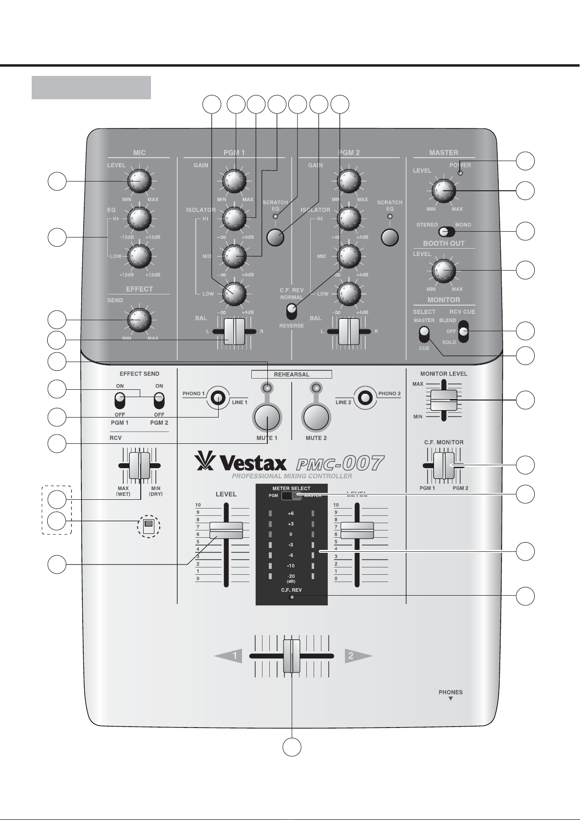
qMIC LEVEL
This switch is used to adjust the signal level of the Main
MIC input.
wMIC EQ
The2-Band MIC EQ feature is used to adjust the equalization
level of the High & Low frequencies on the MIC input
signal. These levels can be adjusted to/by +/-12dB.
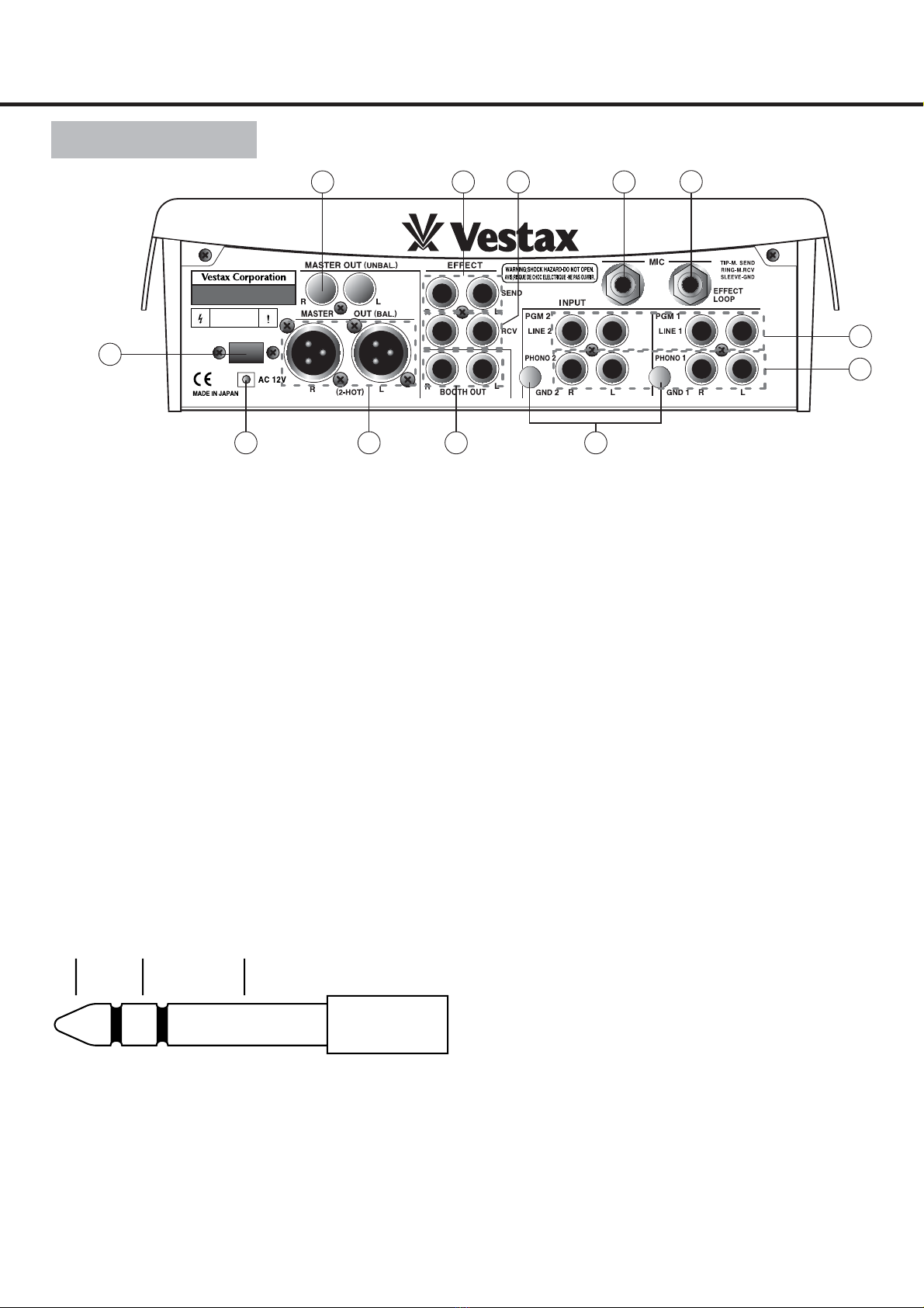
eEFFECT SEND LEVEL
This knob is used to adjust the signal level from an
external effects device connected to the AUX send input
jack on the rear panel of this mixer.
rGAIN
The GAIN controls (on both PGM 1 & 2) are used to adjust
input signal levels. For optimal acoustic quality first set the
level of the input fader @3 to a position of 7 or 8, then, make
any necessary adjustments to the GAIN control so that a
sufficient signal is fed through the channel (PGM) without
distorting.
tHI ISOLATOR
This knob is used to adjust the HI frequency signal level
relevant to each PGM.
yMID ISOLATOR
This knob is used to adjust the MID frequency signal
level relevant to each PGM.
uLOW ISOLATOR
This knob is used to adjust the LOW frequency signal
level relevant to each PGM.
iSCRATCH EQ
This button is used to activate the scratch EQ feature
(new) on this mixer. The scratch EQ feature essentially
disregards the manual isolator EQ setting and passes all
signal feeds through a Mid Boost and Hi Boost EQ and
Low Cut circuit (per PGM), which is designed to
generate the best scratch EQ setting possible.
oSCRATCH EQ INDICATOR
This LED will be illuminated when the Scratch EQ
feature iis on.
!0 PGM BALANCE
This fader is used to adjust the stereo balance on each
PGM. The PGM Balance can also be used to adjust an
unbalanced stereo image. From the center position a
movement to the right will increase the volume of the
signal R over L and vice versa.
!1 CF REVERSE SWITCH
This switch is used to reverse the direction of the cross
fader (CF) such that if reversed position 1 becomes position
2 and vice versa. When reverse mode is activated the CF
REV LED @6 will be illuminated in the main LED section.
!2 MASTER LEVEL
This knob is used to adjust the signal levels from the Line
Out connections found on the rear panel of this unit.
!3 STEREO/MONO SELECT SWITCH
This switch is used to select either a mono or stereo
signal output for the Line Out section. Regardless of your
choice, the L & R levels will remain the same.
!4 BOOTH LEVEL
This knob is used to adjust the level of output through the
Booth section.
!5 MONITOR SELECT SWITCH
This switch is used to select which type of monitor signal,
either CUE or MASTER, is heard in headphones connected
to this mixer. When set to CUE, both signals (including the
EQ settings on each) will be heard. Using the CF Monitor
Fader @9 will alter what is heard in the headphones.
!6 RECEIVE CUE SWITCH
This switch has three settings, which in turn control how
the Effect Received signal is monitored. When set to
BLEND, users will hear both the effect receive signal and
either the Cue or Master output (see 15 for more). When
set to OFF, no effect receive signal will be heard. When
set to SOLO, only the effect receive signal will be heard.
!7 POWER INDICATOR
This LED will be illuminated when powered.
!8 EFFECT SEND ON/OFF SWITCH
When on this feature will send the PGM signal (1 & or 2)
to the effects send jack found on the rear panel.
!9 EFFECT RECEIVE LEVEL
This fader when moved from DRY to WET is used to adjust
the signal level received from any external effects device
connected to the Effect Receive input located on the rear
panel of this unit.
@0 PHONO/LINE SELECTOR
This switch is used to determine which input source is
sent to the PGM. Once an input is connected to the
correct PGM jack users are able to switch back and
forward between either phono or line signals, effectively
creating a type of transformer scratch.
@1 REHEARSAL MUTE SWITCH
When activated this switch restricts the signal path of the
PGM to only the headphone monitor, allowing you to
practice a mix or scratch using the master CF but without
the sound being outputted. Moreover, any adjustment to
the monitor CF will have no effect to the headphone signal
whilst the Freeze feature is active. Pressing both PGM 1 &
2 Freeze switches will result in all output being muted.
When PGM 1 Freeze is on, the LED indicator above the button
will illuminate and all signals from PGM will be routed only to
the headphone section and thus not outputted. Moving the CF
from position 2 to 1 will have only an effect in the headphones,
facilitating practice of a mix point or scratch point.
When PGM 2 Freeze is on, the LED indicator above the button
will illuminate and all signals from PGM will be routed only to
the headphone section and thus not outputted. Moving the CF
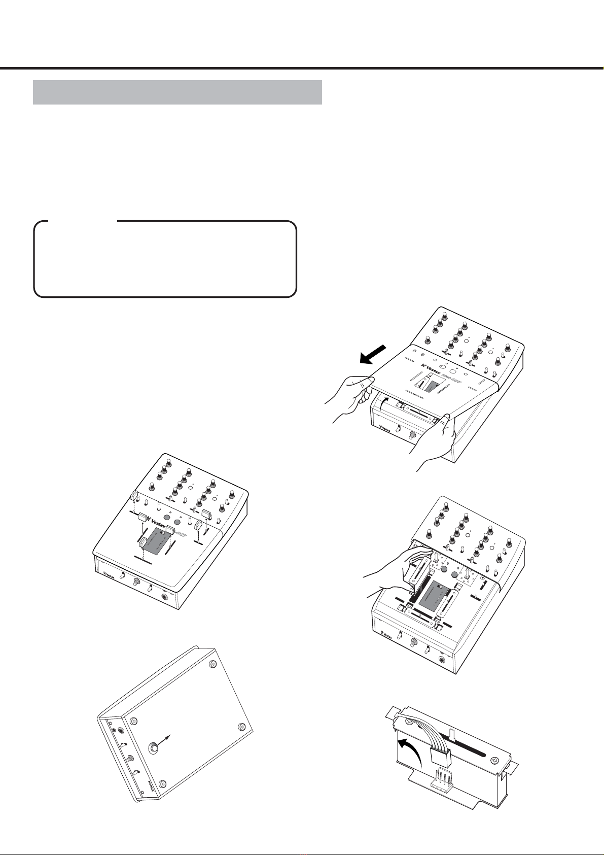
CAUTION
Afunctioncanbechangedwiththeswitch(*)undera
toppanel.Onlythelevelofthesignal(RCVsound)
inputtedfromtheEFFECTRCVjackisadjustedat
thetimeofSwitchOFF(atthetimeofainitialsetup),
anditchangestothebalanceregulationvolumeof
RCVsoundandthesoundofMASTEROUTatthe
timeofSwitchON.