manuals.online logo
Brands
  1. Home
  2. •
  3. Brands
  4. •
  5. Vestil
  6. •
  7. Storage
  8. •
  9. Vestil STOR-44-G-W-1RH User manual

Vestil STOR-44-G-W-1RH User manual

This manual suits for next models

4

Other Vestil Storage manuals

Vestil CYL-H-4-KD Quick guide

Vestil

Vestil CYL-H-4-KD Quick guide

Vestil HDC-450 Series User manual

Vestil

Vestil HDC-450 Series User manual

Vestil DCT-2000 User manual

Vestil

Vestil DCT-2000 User manual

Vestil VHSR Series User manual

Vestil

Vestil VHSR Series User manual

Vestil CYL-V Series Quick guide

Vestil

Vestil CYL-V Series Quick guide

Vestil CYL-H-4-KD Quick guide

Vestil

Vestil CYL-H-4-KD Quick guide

Popular Storage manuals by other brands

IBM 40/80 GB HH DLTVS user guide

IBM

IBM 40/80 GB HH DLTVS user guide

Synology DiskStation DS716+II Quick installation guide

Synology

Synology DiskStation DS716+II Quick installation guide

Vantec NexStar-HX4 user manual

Vantec

Vantec NexStar-HX4 user manual

LaCie Christofle Galet datasheet

LaCie

LaCie Christofle Galet datasheet

LaCie Rugged Thunderbolt user manual

LaCie

LaCie Rugged Thunderbolt user manual

OCZ IBIS datasheet

OCZ

OCZ IBIS datasheet

Transcend JetFlash 110 Brochure & specs

Transcend

Transcend JetFlash 110 Brochure & specs

QNAP TS 32PXU Series user guide

QNAP

QNAP TS 32PXU Series user guide

LaCie RUGGED RAID user manual

LaCie

LaCie RUGGED RAID user manual

Freecom CLS DOCK Quick install guide

Freecom

Freecom CLS DOCK Quick install guide

PNY Attache P-FD64MBATT3 install guide

PNY

PNY Attache P-FD64MBATT3 install guide

OWC Mercury Elite Pro Dual mini Assembly manual

OWC

OWC Mercury Elite Pro Dual mini Assembly manual

OLT 6x6 Maximizer Assembly manual

OLT

OLT 6x6 Maximizer Assembly manual

Transcend JetFlash 160 Specifications

Transcend

Transcend JetFlash 160 Specifications

Thunderbolt 600 user manual

Thunderbolt

Thunderbolt 600 user manual

Intel RAID High Availability user guide

Intel

Intel RAID High Availability user guide

LaCie 12big Thunderbolt 3 Quick install guide

LaCie

LaCie 12big Thunderbolt 3 Quick install guide

Spectra Logic T-Series Spectra T50e quick start guide

Spectra Logic

Spectra Logic T-Series Spectra T50e quick start guide

manuals.online logo
manuals.online logoBrands
  • About & Mission
  • Contact us
  • Privacy Policy
  • Terms and Conditions

Copyright 2025 Manuals.Online. All Rights Reserved.

TABLE OF CONTENTS Copyright 2021 Vestil Manufacturing Page 1of 19
VESTIL MANUFACTURING CORP.
2999 N. Wayne St., Angola, IN 46703
Ph: 260-665-7586 · Fax: 260-665-1339
E-mail: info@vestil.com · Website: www.vestil.com
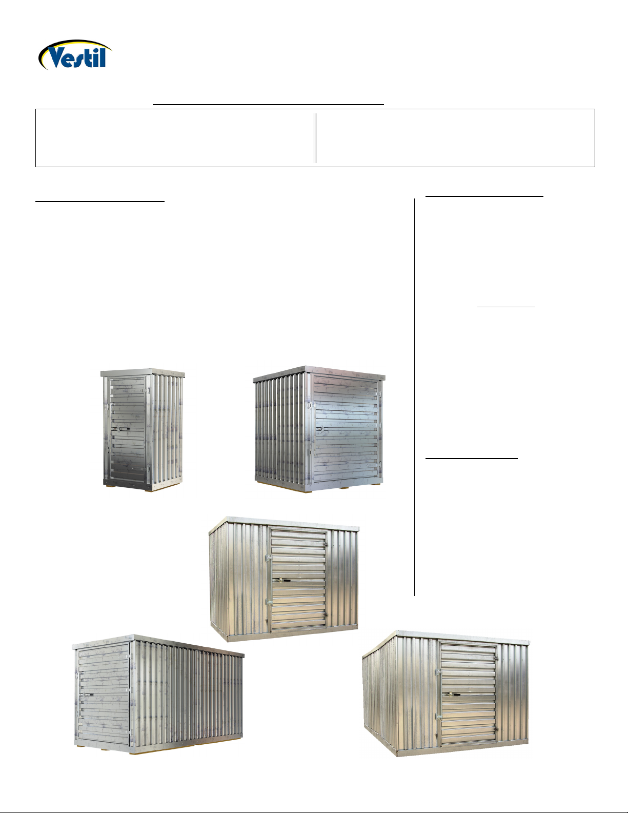
STORAGE SHED MODELS: STOR-96-G-W-1RH & STOR-912-G-W-1RH
OWNER’S
MANUAL
SAFETY INSTRUCTIONS
WARNING: Read and understand these instructions before assembling the
shed.
•DO NOT attempt to assemble/install this product until you read and
understand the entire owner’s manual. All persons who will install, use, or
care for this product must be familiar with this material.
•Ensure that all labeling applied to the shed is in place and legible.
•DO NOT modify the unit without the manufacturer’s approval. Unapproved
modifications automatically void the limited warranty (p. 19), and might
make the shed unsafe to use.
•Maintenance and repairs are to be done only by personnel qualified to
perform the required work. Consideration will not be given for warranty
repair charges without prior written authorization by the manufacturer.
RECEIVING INSTRUCTIONS
It is possible that this product
could incur damage during
transit.
Inspect the unit closely when
it arrives. If you see evidence
of damage or rough handling to
either the packaging or to the
product when it is being
unloaded, immediately make a
note of it on the Bill Of Lading!
It is important that you
remove the product’s packaging
upon its arrival to ensure that
there is no concealed damage
or to enable a timely claim with
the carrier for freight damage.
Also verify that the product
and its specifications are as
ordered.
TOOLS REQUIRED
-7/16” socket or wrench
-1/2” socket or wrench
-5/16” nut driver for drill
-Level
-Eye/Hand protection advised
Note – At least two people
required to assemble this
product; three suggested.
STOR-612-G-W-1RH
STOR-96-G-W-1RH
STOR-66-G-W-1RH
STOR-912-G-W-1RH
STOR-44-G-W-1RH
Table of Contents
Page
Table of Contents
Page
Safety Instructions………………………………………………
1
Exploded Views…………………………………….….………
13-18
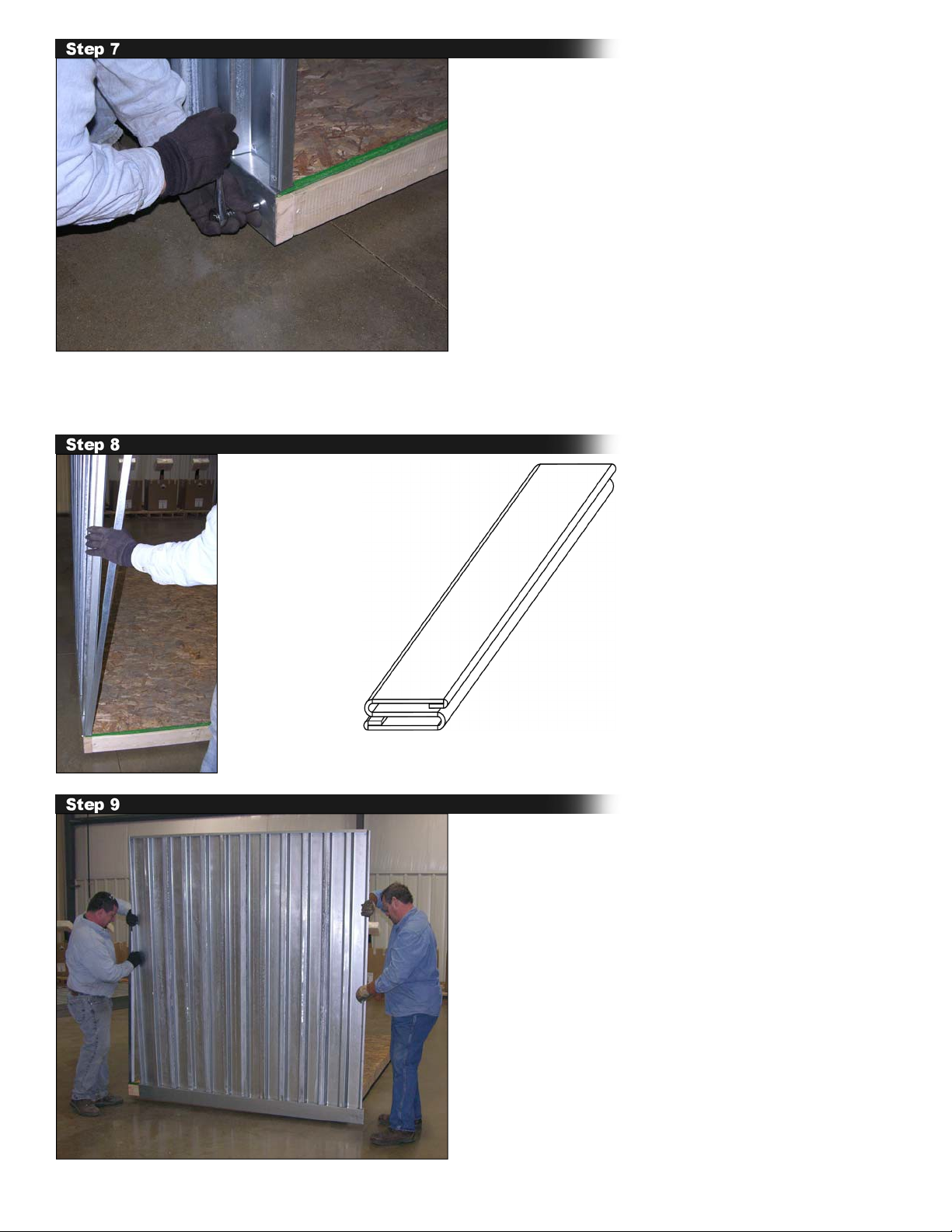
Assembly Instructions: STOR-44/66/96………………
2-5
Limited Warranty…………………………………….………
19
Assembly Instructions: STOR-612/912……………….
6-12
STOR-96 and 912-G-W-1RH 0116
Copyright 2016 Vestil Mfg. Co.
Page 2 of 15
ASSEMBLY INSTRUCTIONS
Review the applicable bill of materials located on pages 13-18. Unpack all materials and verify quantities before
starting.
Consult the factory in the event there are any questions or problems at the time of installation, or for
information regarding optional features not covered by the owner’s manual.
---------------------------------------------------------------------------------------
SINGLE STORAGE UNIT MODEL STOR-44/66/96-G-W-1RH (STOR-96 shown)
Place WOODEN FLOOR BASE on clean and level surface.
Position BACK WALL SUBASSEMBLY as shown above.
NOTE: Install on one of the lengthwise sides of the FLOOR BASE.
STOR-96 and 912-G-W-1RH 0116
Copyright 2016 Vestil Mfg. Co.
Page 3 of 15
Fasten BACK WALL to the wooden floor by installing ¼”x2” lag screws (part no. 22061) through the 5
predrilled holes in the bottom flange of the BACK WALL. Continue supporting the BACK WALL until is
fastened to at least 1 SIDE WALL SUBASSEMBLY this is also lagged to the wooden floor.
Install a CORNER LOCK STRIP on both (vertical) edges of the BACK WALL.
Insert the edge of one SIDE WALL into one of the
LOCK STRIPS installed in Step 4.
CORNER
LOCK STRIP
STOR-96 and 912-G-W-1RH 0116
Copyright 2016 Vestil Mfg. Co.
Page 4 of 15
Insert a side edge of the remaining SIDE WALL into the other LOCK STRIP. Brace the bottom of the
SIDE WALL while inserting the edge.
Fasten both SIDE WALLS to the wooden floor with ¼”x2” lag screws (22061) installed through the 5
predrilled holes in the bottom flange of each SIDE WALL.
Install a LOCK STRIP on the free edge of both SIDE WALLS. Insert the side edges of the FRONT
WALL SUBASSEMBLY into the LOCK STRIPS. Fasten FRONT WALL to the floor with ¼”x2” lag
screws installed through the 5 predrilled holes in the bottom flange of each SIDE WALL.
FRONT WALL
shown without door.
STOR-96 and 912-G-W-1RH 0116
Copyright 2016 Vestil Mfg. Co.
Page 5 of 15
Place the ROOF WALL SUBASSEMBLY on top of the wall panels. The perimeter flange of the ROOF
WALL SUBASSEMBLY must be on the outside of the wall panels. Pull/tap the ROOF WALL down until
it seats onto the tops of the supporting wall panels.
Fasten the ROOF to the front and back walls with 8pc of 1” long self-tapping screws (part no. 31806; 4 pcs.
per wall). There are no predrilled holes. Space screws evenly across both walls.
Assembly is now complete.
STOR-44-G-W-1RH STOR-66-G-W-1RH STOR-96-G-W-1RH
STOR-96 and 912-G-W-1RH 0116
Copyright 2016 Vestil Mfg. Co.
Page 6 of 15
DOUBLE STORAGE UNIT MODEL STOR-612-G-W-1RH & STOR-912-G-W-1RH
Fasten a 2”x 4” to one of the 9 foot (STOR-912) or 6ft. (STOR-612) sides of each WOOD FLOOR BASE.
Attach 2x4’s ¾” from top of floor bases (thickness of plywood) using 6pc – 3” long wood screws as evenly
spaced as possible.
Place wooden floors with 2”X4” joints together on a level surface and position pre-cut spacers as shown.
Using 20pc of 2” long wood screws fasten the
plywood spacer strips directly to the 2”X4” joints.
Evenly space wood screws along entire length of
spacer strip. NOTE: Attach screws evenly to both
2x4’s.
STOR-96 and 912-G-W-1RH 0116
Copyright 2016 Vestil Mfg. Co.
Page 7 of 15
Install a FLOOR SEAM COVER PLATE on both sides to the center of the two joined wooden floors with a
¼” x 2” lag screw (part no. 22061) – one bolt per face joint on each side for the wooden floors.
Begin shed assembly with wooden floors on clean level surface.
Position BACK WALL SUBASSEMBLY as shown above.
STOR-96 and 912-G-W-1RH 0116
Copyright 2016 Vestil Mfg. Co.
Page 8 of 15
Lock strip
Secure BACK WALL SUBASSEMBLY to the wooden floor installing ¼”x 2” lag screws into the 5 predrilled
holes in the bottom flange. The BACK WALL will fall over until it is attached to at least one SIDE WALL
SUBASSEMBLY. Support the back wall until it is attached to at least one side wall and both walls are securely
lagged to the wooden floor.
Install a CORNER LOCK STRIP on both (vertical) side edges of the back wall.
Install a SIDE WALL SUBASSEMBLY by inserting a side edge into one of the lock strips.
STOR-96 and 912-G-W-1RH 0116
Copyright 2016 Vestil Mfg. Co.
Page 9 of 15
Install LOCK STRIP on the free end of each SIDE
WALL and then install a SIDE WALL CONNECTOR
(part no. 41-014-032), as seen above on right hand side
.
See
step 13 for installation. NOTE: The concavity of the
SIDE WALL CONNECTOR should face outwards.
SIDE WALL CONNECTOR with
concavity facing outward.
Install another SIDE WALL SUBASSEMBLY on opposit
e side
of BACK WALL. Brace the bottom of the side wall while
inserting it into LOCK STRIP.
Secure both side walls to the wooden floor using
¼” X 2” lag bolts into the 5 predrilled holes on each
side.
STOR-96 and 912-G-W-1RH 0116
Copyright 2021 Vestil Mfg. Co.
Page 10 of 15
Insert the flange of one side of the SIDE WALL CONNECTOR into LOCK STRIP. Then, apply a LOCK STRIP to
other flange of the SIDE WALL CONNECTOR. Repeat this step with the opposite side wall.
Install another SIDE WALL SUBASSEMBLY on each side. Then install 10pc ¼”x2” lag bolts to secure walls to
wooden floor. There are 5 predrilled holes at the bottom of each SIDE WALL SUBASSEMBLY.
Install a LOCK STRIP on the free end of each SIDE WALL; then insert FRONT WALL assembly into the LOCK
STRIPS. Install 5pc of ¼”x2”lag screws into predrilled holes to attach the FRONT WALL to the floor.
Photo shows FRONT WALL ASSEMBLY of STOR-912
without door.