Vetek AWT20L User manual

Installation user’smanual
AWT20L
AND
AWT20L5
WEIGHTTRANSMITTER
AWT20L_07.10_UK

LEGEND
Below are shown thesimbologiesused inthemanualinordertowarn the reader:
Caution !High Voltage!
Caution !Thisoperation must be executedbyskilled workers.
Read carefullythe following indications.
Furtherinformation.
SYSTEM IDENTIFICATION

2
TABLEOF CONTENTS
RECOMMENDATIONS FOR THE CORRECTINSTALLATION.............................................................................3
TECHNICAL FEATURES.......................................................................................................................................4
ELECTRICAL CONNECTIONS..............................................................................................................................5
PUTTING INTO OPERATIONS...............................................................................................................................6
TARE-ZERO SETTING:..........................................................................................................................................6
MECHANICAL INSTALLATION CHECK................................................................................................................7
CALIBRATION .......................................................................................................................................................8
LOAD CELLS VERIFY..........................................................................................................................................11
ANALOG OUTPUT MODIFY.................................................................................................................................12
TRANSMITTERAWT20L +/-5VCC VERSION......................................................................................................13
TARE-ZERO SETTING (+/-5VCC VERSION).......................................................................................................13
CALIBRATION OF INSTRUMENT (+/-5VCC VERSION).....................................................................................14
EARTHING SYSTEM............................................................................................................................................15
DECLARATION OF CONFORMITY......................................................................................................................17

3
RECOMMENDATIONSFORTHECORRECTINSTALLATION
OF THELOAD CELLSAND THEMICROPROCESSORSYSTEMS
1)Avoid welding while the load cellsareinstalled.
2)By meansofacopperwireconnecttheuppersupporting platewiththe lowersupportingplate,then
connect all the upperplatestothe earthing system.
3)Usewater-proofsheathesand jointsin ordertoprotect the cells'cables.
4)Carry outthe parallel connectionofthe cellsbyusingawater-proofjunction boxandterminal box
completewithaplatecable clamp.
5)Boththe extension cablesconnectedtothe load cellsandthe cablesrelevanttothe signal amplifiers
must be led alone intothe piping ortrough and laid asfaraspossible fromthe powercables.
6)The entryintothe cable boardofbothcellsand amplifiers mustbe independent(on one side orthe
otherof the board)anddirectlyconnected totheterminal boardof the devicewithout being interrupted by
bearing terminal boardsorpassing through troughscontaining othercables.
7)Usethe "RC "filterson the microprocessor-driven coilsof the remotecontrol switches.
8)It isagood norm tolet the microprocessoralways switchon toprevent the formation of condensation.
9)The installerofthe boardisresponsible forsecuring the electrical safetyofthe instruments
(fuses,door-locking switch, etc. ).

4
AWT20L TRANSMITTER
DIMENSIONS:base114 mm ,depth93 mm, high 60 mm.
MOUNTING: instrument formounting back panel orin junction box.
BOXCONTAINER (in resin ): forDINoromega bar.
TECHNICALFEATURES:
POWER from20 to28Vdc
PRECISION 0,25 %
REPEATIBILITY 0,01 %
POWERCONSUMPTION 6VA
PROTECTIONDEGREE IP50
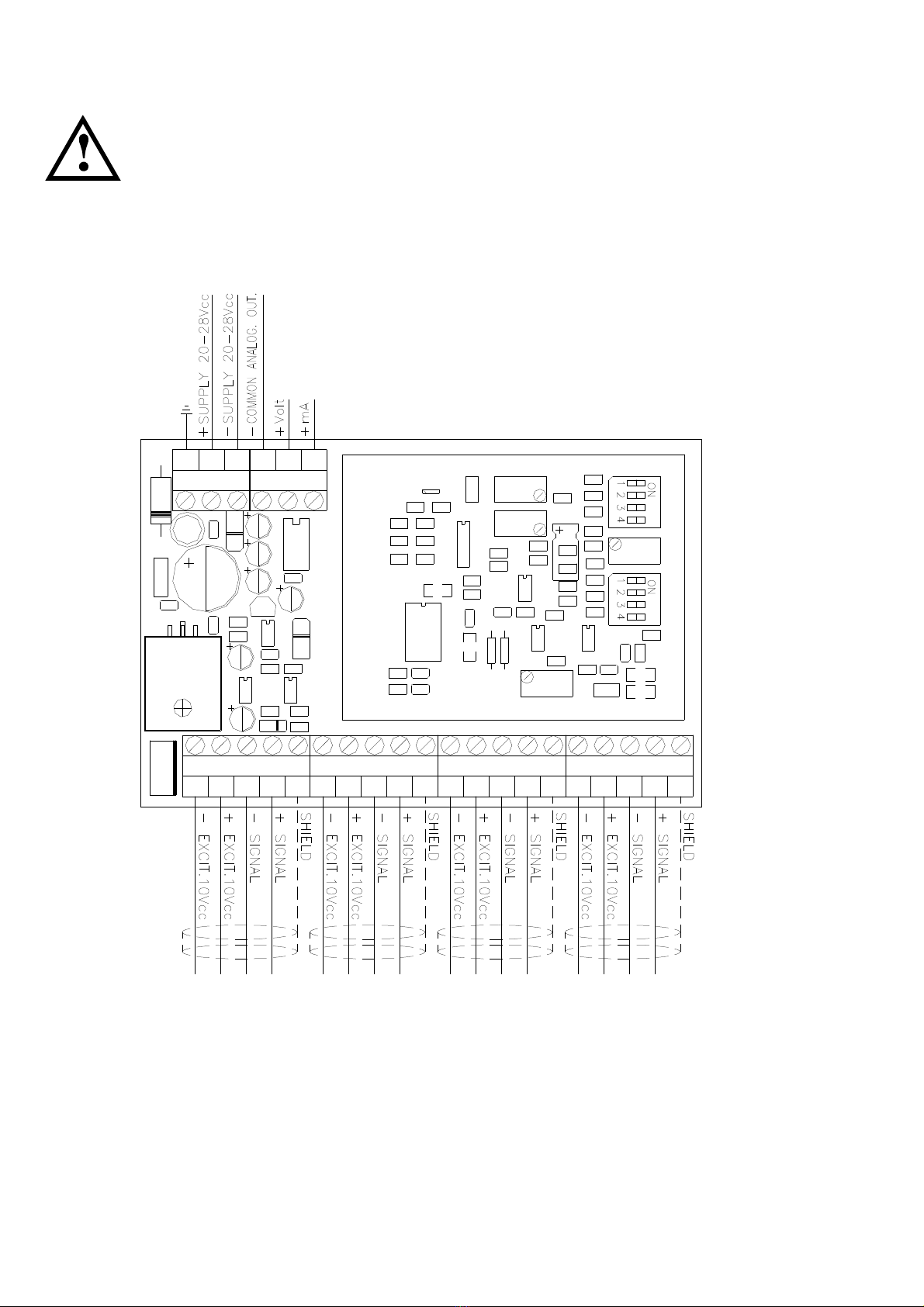
CAPACITY6load cellsin parallel 350 Ohm
LOAD CELL CONNECTION 4-wirestechnique
LOAD CELL SUPPLY 10 Vdc+/ -3%
MEASURINGRANGE from3,5to24 mV
COARSE ZERO by4dip-switches, 70%range
FINEZERO bytrimmer10%range
COARSE FULL SCALE by4dip-switches
FINEFULL SCALE bytrimmer,10%range
OPERATINGTEMPERATURERANGE -10 to+50 °C
STORAGETEMPERATURERANGE -20 to+70 °C
THERMICSTABILITY 0,01 %of range for10°C
TIMEOFTHERMICSTABILIZATION 10 minutes
ANALOGOUTPUT :
AWT20L isprovided withthe following outputs:
0-10 Vdc(terminals22-23 )
0-20 mA, 4-20 mA(terminals21 -23 )
Tomodifythe outputfollow the proceduresatchapterANALOG OUTPUTMODIFY. In thestandard
version inorder toincrease theinputfield upto35 mVenter in parallela49,9K resistance;see
ANALOGUEOUTPUTMODIFICATIONsection forfurther details.
NOTE:
Thereisalsoanotherversion of the AWT20L transmitterwhichhasan output voltage of +/-5Vcc.
USE:
Normallyused witha12 bit analog / digital boardsinstalled on programmable logic(PLC )

5
ELECTRICALCONNECTIONS
WARNING:Theprocedures here belowdescribedhave tobecarriedoutbyspecialized
personnelonly.
2019181716151413121110987654321
Filter
23 2122252426
F.S.
E2
ZERO
ZERO

6
PUTTINGINTOOPERATIONS
START-UP:
Supplythe instrumentand waitforabout10minutessothatallcomponentsreachasteadytemperature.
Makesurethatthe containerisemptyand without mechanical constraints.
By using atestermakesurethatthe outputispositiveand itincreasesifyou subjectthe containertoa
forceweight, in casetheoutputisnegativecheck forthe load cellsconnection and the correctload cells
installation (direction of charge ).
TAREZERO-SETTING:
Makesurethatthe containerisemptyand setthe taretozeroasfollows:
Usethe zerofine trimmerforlittle variations,ifitisn'tsufficientusethe dip-switchesofcoarsezeroto
approachzerodisplayasmuchaspossible, thenusethe trimmeroffine zeroagain.
DIP-SWITCHES OFCOARSE ZERO
0=OFF1=ON
REGISTEREDVALUESWITH 1001 AMPLIFICATION AND ALL AMPLIFICATION TRIMMERCLOCKWISE
input mV toset tozero
DIP-SWITCHES
POSITION
from-mV
ALL ZEROTRIMMER
ANTICLOCKWISE
to-mV
ALL ZEROTRIMMER
CLOCKWISE
1234
0000
1000
0100
1100
0010
1010
0110
1110
0001
1001
0101
1101
0011
1011
0111
1111
----
-2,4
-0,2
1,7
3,4
4,9
6,2
7,3
8,4
9,4
10,3
11,1
11,8
12,5
13,1
13,7
14,3
----
-0,4
2,6
4,5
6,2
7,7
9,1
10,2
11,3
12,3
13,2
14,0
14,7
15,4
16,0
16,6
17,2

7
WEIGHTOSCILLATIONS:
If the displayed weightisnotsteadyitispossible tousean analogicfilter.Turnthe trimmerclockwisein
ordertoreducethe oscillations. Toinactivatethefilterremovethe E2jumper.
CALIBRATIONCHECK:
The instrumenthasbeen suppliedalreadycalibrated.If you wanttocheck it, afterthe tarezero-setting,
putacalibrating weightequal toatleast50%ofthe maxload capacityon the load systemandcheck the
value ofthe outputsignal;ifthe outputisdifferentfromthe calibrating weightverifythatthe weight
differencedoesnotdepend fromsomemechanical cause,eventuallymovetothe Mechanical Installation
Check.
MECHANICALINSTALLATIONCHECK
Withatestermeasurethe load cellssupplyon the terminals1and 2and makesurethatthereisasupply
of about 10 Vdc).
When the containerisemptymeasurethe signal in mV on the terminals3and 4.
Put acalibrating weight on the scale and measurethe signal in mV again.
Makesurethatthe signal increasecorrespondstothe resultofthe following equation:
mVtot:F.S. cells=mVS : S
mVtot=Millivolt correspondingtoload cellssupplyxrated output
F.S. load cells=Full Scale (numberof load cellsxrated load )
mVS =Millivolt increasesbecauseof calibrating weight
S=calibrating weight
EXAMPLE:
n° load cells=3; ratedload =1500 kg; rated output =2mV/ V;
load cellssupply=9,98 Vdc;calibrating weight=1000 kg;
mVtot:F.S. cells=mVS : S
(9,98 x2):(1500 x3)=x: 1000
19,96 : 4500 =x: 1000
x=(1000 x19,96 ): 4500 =4,435
sowithacalibrating weight of 1000Kgon full scale of 4500 Kg, the increment will be: 4,435 mV.

8
-If the value in mV iscorrectand the outputsignal iswrong,probablynon-authorised operators have
changed the full scale bymistake,thereforemoveon tothe Calibration page.
-If the value in mV islowerthanthe calculated value,probablytherearemechanicalfriction,after
verifying themmoveon tothe Loadcellscheck.
-If the value in mV issuperiortothe calculated value moveon tothe Load cellscheck.
CALIBRATION
Makesurethatthe containerisempty,verifythatthe outputis0Vdcor0mA or4mA (inaccordancewith
model used),then putacalibrating weightequal toatleast50%ofthefull scale and usethetrimmerof
fine full scaletomovethe corresponding outputtothe exactvalue,ifthe trimmerisn'tsufficientusethe
dip-switchesofcoarsefull scale.Then check the 0Vdcor0mA or4mAagain,andifnecessary adjustit
again; put the calibrating weight and check the output, repeat thisoperation until the output iscorrected.
DIP-SWITCHES OFCOARSE FULL SCALE
toobtain 20 mAor10 VdcoutputcorrespondingtotheinputmV
0=OFF1=ON
REGISTERED VALUES WITH ZERODIPSWITCHES IN 0000 POSITION AND ALL ZEROTRIMMER ANTI CLOCKWISE
input mV to obtain 10Vdc or 20mAoutput
DIP-SWITCHES
POSITION
from-mV
ALL AMPLIFICATION
TRIMMER
ANTICLOCKWISE
to-mV
ALL AMPLIFICATION
TRIMMERCLOCKWISE
1234
1111
0111
1011
0011
1101
0101
1001
0001
1110
0110
1010
0010
1100
0100
1000
0000
----
31,2
20,8
15,5
12,5
10,3
8,8
7,7
6,9
6,3
5,8
5,3
4,9
4,5
4,2
3,9
3,7
----
19,5
14,8
12,0
10,0
8,6
7,5
6,7
6,1
5,6
5,2
4,8
4,5
4,2
3,9
3,7
3,5

9
CALIBRATIONTHROUGHSIMULATOR
Useacell simulatorand atesterwithscale in mVand at least anumberafterthe comma.
Connect the simulatortothe AWT20L.
Measurethe mVin inputon the terminals4(+)and 3(-)and verify0mV;verifythatthe mA orVdc
outputis0-4mA or0Vdc(in accordancewiththe model used )otherwiseusethe dip-switchesofcoarse
zeroand the trimmeroffine zerotomovethe outputtothosevalues(usuallythe dip-switch1isin
position ON).
Measurethe supply(about 10V+/-3%)on theterminals1(-)and 2(+).
Multiplythisvalue bythe rated outputofthe cells(mV/V)toobtainthe mV value in input, rotatethe
simulatortoobtain thisvalue on the terminals4(+)and 3(-).
Usethe dip-switchesand the trimmeroffine full scale toobtain in output 20 mAor5-10 Vdc.
Bring the mVinput tozeroand check the 4-0mA or0Vdcoutput,otherwiseadjust the new value.
Movethe mVinputtothe full scale (load cellssupplyxrated output)and makesurethatthe output
signal is20 mA or10 Vdc.
Adjust the full scale ifnecessary.
If you wantthe signal 20mA or10Vdcnotatthe cellsfull scalebutatamiddle value corresponding tothe
net weight, usethe following equation tocalculatethe input value in mV:
mVtot:F.S.cells=mVS : S
mVtot=Millivolt correspondingtoload cellssupplyxrated output
F.S. cells=Full Scale (numberof load cellsxrated load )
mVS =Millivolt input
S=weight forthe one you want the 10Vdcor20mA output
Example:
load cellssupply=9,99 ;
rated output =2mV/V;
n° cells=4;
rated load =2500 kg;
weight forthe one you want the 10 Vdcor20 mA output =4000 kg

10
mVtot:F.S.=mVS: S
(9,99 x2):(2500 x4)=x: 4000
19,98 : 10000 =x: 4000
x=(19,98 x4000 ): 10000 =7,992mV
sowithainput signal of7,99 mV the outputsignal obtained must be 10 Vdcor20 mA.

11
LOAD CELL VERIFICATION
Loadcellsresistance measure:
Useatesterwithasupplynot higherthan 9Vdc.
-Disconnectthe loadcellsfromthe AWT20L,makesurethatthereisnotanymoistness caused by
condensed waterorinfiltration of water. If so,keep cleaning the systemorreplaceit, if
necessary.
-Carryout the measurement of the resistanceasfollows:
-The value between thepositivesupplyandthe negativesupplymustbe about350 ohmorsimilartothe
one indicated on the loadcell datasheet.
-Value between thepositivesignalandthe negativesignal mustbeabout350ohmorsimilartothe one
indicated on the load cell datasheet.
-The insulation value between the shield and anyothercoresmust be higherthan 20 millionsohm.
Loadcellstensionmeasure:
Useatesterwithasupplynot higherthan 9Vdc.
-Fromunderneaththe containertakeout the cell you intend tocheck
-Connectthe positiveand negativesupplyofthe loadcelltothe AWT20L andmakesurethatthereisa
supplyof 10 Vdc+/-3%.
-Measurethesignal between thepositiveand the negativesignalwiresdirectlyconnected tothe
multimeter, makesurethat thereisasignal between 0and 0,5mV dc(thousandthof aVolt).
-Load the cell and makesurethatthereisan increaseof the signal.
INCASE ONEOFTHEABOVE CONDITIONSISNOTMET, PLEASE CALL THETECHNICAL
ASSISTANCESERVICE.

12
ANALOGOUTPUT MODIFICATION
-Removethe jumperE1toobtain an analog output of 0-10 Vdc(output on terminals22 -23 ).
-Removethe jumperE1toobtain an analog output of 0-20 mA(output on terminals21 -23 ).
-Closethe jumperE1toobtain an analogoutput of 4-20 mA(output onterminals21 -23 ).
-Toincreasethe taresuppression over17mV putaresistanceof10K(1/8ofWatt)instead ofR33
(normallyis22 k).
-Tohavean analogue output with35 mVin input one must entera49,9Kresistance(1%precision and
temperatureprecision of 15 ppm) in parallel toR11.

13
TRANSMITTER AWT20L +/- 5Vcc VERSION
Forthisversion the calibration proceduresarethe sameasthe standardversion: the valuesofthe
APPROXIMATEZEROand APPROXIMATEF.S.O. tables.
Withthisversion, the calibration can be made sothat the range is:
from0to+5Vifthe instrument iscleared at ange beginning;
from-5Vto0ifcleared at ange end;
from-5Vto+5Vif cleared in the middle of the range.
TAREZERO-SETTING:
Makesurethatthe containerisemptyand setthe taretozeroasfollows:
Usethe zerofine trimmerforlittle variations,ifitisn'tsufficientusethe dip-switchesofcoarsezeroto
approachzerodisplayasmuchaspossible, thenusethe trimmeroffine zeroagain.
DIP-SWITCHES OFCOARSE ZERO
0=OFF1=ON
REGISTEREDVALUES WITH1001AMPLIFICATIONAND ALL AMPLIFICATIONTRIMMERCLOCKWISE
input mV toset tozero
DIP-SWITCHES
POSITION
from-mV
ALL ZEROTRIMMER
ANTICLOCKWISE
to-mV
ALL ZEROTRIMMER
CLOCKWISE
1234
0000
1000
0100
1100
0010
1010
0110
1110
0001
1001
0101
1101
0011
1011
0111
1111
----
-0.9
1,2
3,1
4,7
6,1
7,4
8,6
9,6
10,6
11,4
12,2
12,9
13,6
14,2
14,7
15,3
----
1.9
4,0
5,9
7,6
9,0
10,3
11,4
12,5
13,4
14,3
15,1
15,8
16,4
17,1
17,6
18,2

14
CALIBRATION
Makesurethatthecontainerisempty,verifythatthe outputis0Vdc(in accordancewithmodel used),
then putacalibrating weightequal toatleast50%ofthe full scale and usethe trimmeroffine full scale to
movethe correspondingoutputtothe exactvalue,ifthe trimmerisn'tsufficientusethe dip-switchesof
coarsefull scale.Then check the 0Vdcagain,and ifnecessary adjustitagain;putthe calibrating weight
and check the output, repeat thisoperation until the output iscorrected.
DIP-SWITCHES OFCOARSE FULL SCALE
toobtain 10 VdcoutputcorrespondingtotheinputmV
0=OFF1=ON
REGISTERED VALUES WITH ZERODIPSWITCHES IN 0000 POSITION AND ALL ZEROTRIMMER ANTI CLOCKWISE
input mV to obtain 10Vdc
DIP-SWITCHES
POSITION
from-mV
ALL AMPLIFICATION
TRIMMER
ANTICLOCKWISE
to-mV
ALL AMPLIFICATION
TRIMMERCLOCKWISE
1234
1111
0111
1011
0011
1101
0101
1001
0001
1110
0110
1010
0010
1100
0100
1000
0000
----
27,0
24,9
23,1
21,6
20,4
19,3
18,3
17,5
16,6
16,0
15,5
14,9
14,5
14,1
13,7
13,3
----
24,4
22,7
21,3
20,1
19,0
18,1
17,3
16,6
15,9
15,3
14,8
14,4
14,0
13,6
13,2
12,9

15
EARTHINGSYSTEM
Forthe rightearthing andthe ottimalfunctioningofthesystem,itisnecessarytoconnectthe indicator,the load cells,the
possiblejunctionboxand theweighing structuretothe earth.
TRANSMITTER
Groundterminal26 (SHD) using acoppercablewithasection notless than 16 mm2.
LOAD CELLSAND JUNCTIONBOX
-Inthecasetheload cellsareconnected tothe indicatorthrough ajunction box,itisnecessarytoconnectthe sheathing
bothofcellscablesand ofindicatorcabletothe earthing ofthe junction box(refertothejunctionboxmanual) and
connect thistothe earththroughcoppercableshavingat least a16 mm2cross-section.
-If the loadcellsaredirectlyconnectedtothe indicator(withoutthejunctionbox),one shouldconnecttheshieldsofthe
load cell cablestothe relativeSHD terminals.
Moreoverinbothcasesit isrequired to:
lConnecttheuppersideofeverycellstothe lowersideusingacopperbraidhaving atleast16 mm2 cross-section;
the upperside mustbeshort-circuited withthesurfaceoftheweighing structureand the lowerone mustbe
connectedtotheearthusingacopperbraidhavingat least16 mm2 cross-section.
lUseEarthplateof suitablelength, inordertoobtainatotalresistanceofearthingplant lowerthan1 .
WEIGHING STRUCTURE
Connectthe weighing structureandthe possibleconnected structures(forexamplesilosthatreleasematerialon the
weighingstructure)tothe earththroughcoppercableshavingat leasta16mm2cross-section.
NOTES:
lInthe casethe weighing systemregardsgreatand/oroutdoorstructures,the cross-section mustbe greather(for
example50 mm2), becausethe voltage intoplayisgreather(forexamplethunderbolts).
lInordertoavoidpossibleundesired effects,ifthereareothershieldedcableconnectedtotheindicator(for
instance, PCcable)the shieldshouldbeearthingonlyonthecabletermination towardstheindicator.
lEveryshieldedcableornot(forinstancePCcable,cell cable,powersupplycable)connected tothe indicator
shouldbeasshorteraspossible,then youhavetocomeoutofthe shieldthe minimumlengthofcable,go three
round around aferriteringand thenconnecttothe terminalbox.
lIf the indicatorissituatedinside an electricpanel,the powersupplycableshouldbeashieldedcableasshorteras
possible,distantfromeverycoil supplycable,inverter,electromotiveforce,etc.andinadditiondedicatean
uncouplertransformerinordertofeedthe indicatoronly.

16
EARTHINGEXAMPLE
Non weighing
structure(silo)
Weighing
structure
Load cell
U-bolt between
plateundercell
and weighing
structure(not
supplied)
Ø 4,6–16 mm²
earthcable
section (not
supplied)
Ø 8–50 mm²
earthcable
section (not
supplied)
Junction
box
This manual suits for next models
1
Table of contents