manuals.online logo
Brands
  1. Home
  2. •
  3. Brands
  4. •
  5. Vetus
  6. •
  7. Tank Equipment
  8. •
  9. Vetus ILT120 User manual

Vetus ILT120 User manual

040108.01
NEDERLANDS
ENGLISH
DEUTSCH
FRANÇAIS
ESPAÑOL
ITALIANO
Copyright © 2018 Vetus b.v. Schiedam Holland
Installatie instructies
Inspectiedeksel voor vaste tanks
Installation instructions
Inspection lid for rigid tanks
Einbauanleitung
Inspektionsdeckel für starre Tanks
Instructions d’installation
Couvercle d’inspection pour
réservoirs rigides
Instrucciones de instalación
Tapa de inspección para depósitos rígidos
Istruzioni per l’installazione
Coperchio di ispezione per serbatoi rigidi
Inspection lid for rigid tanks
ILT120
2040108.01 vetus® Inspection lid ILT120
1 Inleiding
Deze handleiding geldt voor het inspectiedeksel
voor vaste tanks.
De tank mag van kunststof, polyester of metaal
zijn gemaakt en moet een minimale wanddikte
hebben van 1,5 mm.
LET OP!
Raadpleeg de bijbehorende handleiding
voor het aansluiten van de tank.
2 Installatie
2.1 Aanbrengen van het montagegat
voor het inspectiedeksel
• Plaats het inspectiedeksel in de bovenzijde
van de tank. Indien een VETUS tank wordt
gebruikt plaats dan het inspectiedeksel bij
voorkeur zo dat de plug P wordt verwijderd
bij het aanbrengen van het gat.
• Breng het gat in de tank aan en werk het gat
braambrij af. Pas bij voorkeur een gatzaag
(ø159 mm) toe.
• Reinig de binnenzijde van de tanks alvorens
het inspectiedeksel te monteren.
2.2 Toe te passen afdichtrubber
Bepaal de wanddikte van de tank en pas het aan-
gegeven afdichtrubber toe.
2.3 Montage inspectiedeksel
Flens (1)
• Plaats de ens (1) in het gat van de tank.
• Draai de 4 schroeven (2) ieder één (-1-) om-
wenteling vast (rechtsom) en test of de ens
nog eenvoudig met de hand te verdraaien
is. Herhaal dit tot de ens niet meer te ver-
draaien is.
• Draai hierna iedere schroef nog vier (-4-) om-
wentelingen vast.
Massa-aansluiting (3)
• De schroef (3) is bestemd om de ens aan
massa te kunnen aansluiten.
Deksel (4)
• Schroef het deksel op de ens.
LET OP!
Controleer de dichtheid van alle
verbindingen alvorens de tank te vullen.
ø 159 (6 1/4”)
MIN. 160
(6 1/4”)
P
T = 1.5 - 4 mm
(1/16”- 5/32”)
T = 4 - 10 mm
(5/32”- 3/8”)
T
16 mm (5/8”)
22 mm (7/8”)
2.1 2.2
1 Introduction
This manual is applicable to the installation of
the inspection lid for rigid tanks.
The tank may be made from plastic, GRP or metal
and should have a minimum wall thickness of
1.5 mm.
NOTE!
Consult the manual supplied with the tank
for instructions on how to connect it.
2 Installation
2.1 Cutting the hole for the
inspection lid
• Position the inspection lid on the top face
of the tank. If a VETUS tank is used, then it
should be tted with plug P on the top and
the inspection lid should preferably be lo-
cated so that plug P is removed when the
hole is cut.
• Cut the hole in the tank and remove all burrs.
Preferably use a holesaw (159 mm, 6 1/4”
diam.).
• Clean the inside of the tanks before tting
the inspection lid.
2.2 Rubber seal to be applied
Determine the thickness of the wall of the tank
and use the indicated rubber seal.
2.3 Installation of connector lid
Flange (1)
• Position the ange (1) into the hole of the
tank.
• Tighten each of the 4 screws (2) one (-1-)
revolution (clockwise) and check if the ange
can be rotated easily by hand. Repeat this un-
til the ange can’t be rotated anymore.
• Then tighten each of the screws another four
(-4-) revolutions.
Ground connection (3)
• Use the screw to connect the ange to ground.
Lid (4)
• Screw the lid onto the ange.
NOTE!
Check the tightness of all connections
before lling the tank.
1 Einleitung
Diese Anleitung gilt für den Inspektionsdeckel
für starre tanks. Der Treibstotank kann aus
Kunstso, GRP oder Metall sein und sollte eine
minimale Wanddicke von 1,5 mm aufweisen.
ACHTUNG!
Konsultieren Sie das Handbuch das mit dem
Tank geliefert wurde für Anweisungen zu
den Verbindungen.
2 Installation
2.1 Herstellen des Montagelochs
für den Inspektionsdeckel
• Bringen Sie den Inspektionsdeckel an der
Oberseite des Tanks an. Handelt es sich um ei-
nen Vetus-Tank, bringen Sie den Inspektions-
deckel vorzugsweise so an, dass das Anguss-
teil P beim Herstellen des Lochs entfernt wird.
• Stellen Sie das Loch an der betreenden Stel-
le des Tanks so her, dass es frei von Riefen ist.
Verwenden Sie dazu vorzugsweise eine Loch-
säge (ø 159 mm).
• Reinigen Sie den Tank von innen, bevor Sie
den Inspektionsdeckel montieren.
2.2 Zu verwendender Dichtgummiring
Stellen Sie die Wanddicke des Tanks fest und ver-
wenden Sie den angegebenen Dichtgummiring.
2.3 Montage des Inspektionsdeckels
Flansch (1)
• Montieren Sie den Flansch (1) in das Loch am Tank.
• Ziehen Sie die 4 Schrauben (2) jeweils um
eine (-1-) Umdrehung fest (rechts herum) und
testen Sie, ob der Flansch noch einfach mit
der Hand verdreht werden kann. Wiederho-
len Sie diesen Vorgang, bis der Flansch nicht
mehr verdreht werden kann.
• Ziehen Sie dann jede Schraube noch vier (-4-)
Umdrehungen fest.
Masse-Anschluss (3)
• Die Schraube (3) hat den Zweck, den Flansch
an ein Massekabel anschließen zu können.
Deckel (4)
• Schrauben Sie den Deckel auf den Flansch.
ACHTUNG!
Prüfen Sie die Dichtheit aller Verbindungen
vor dem auüllen der Treibstotanks.
ENGLISH
NEDERLANDS DEUTSCH
040108.01 3
vetus® Inspection lid ILT120
42
1
3
4
2.3
1 Introduction
Le mode d’emploi se rapporte au couvercle
d’inspection pour réservoirs rigides. Le réservoir
peut être fait en plastique, en plastique renforcé
de bre de verre (GRP) ou en métal et doit avoir
une épaisseur minimale de paroi de 1,5 mm.
REMARQUE !
Consulter le manuel fourni avec le réservoir
de carbunant pour obtenir des instructions
sur la manière de le connecter.
2 Installation
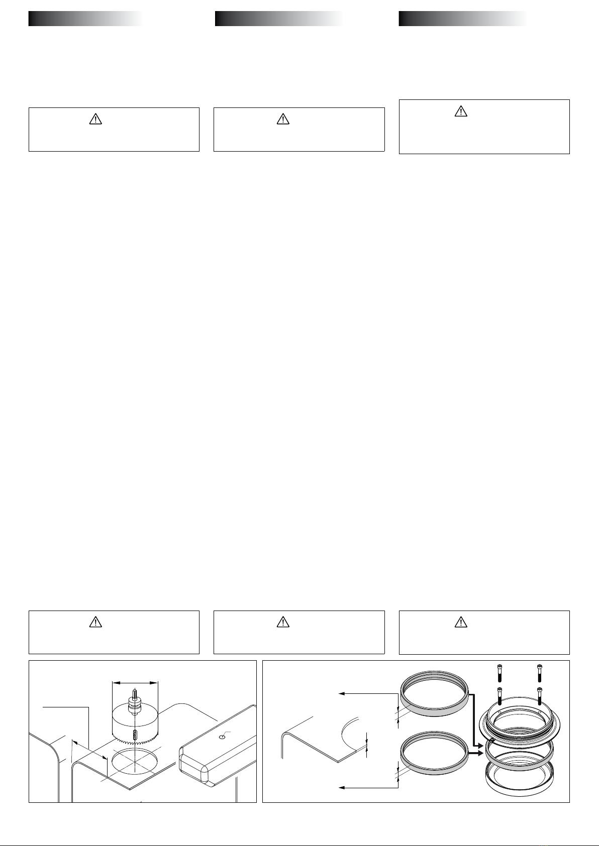
2.1 Perçage du trou pour le couvercle
du connecteur et les trous pour le
raccord
• Perçage du trou de montage pour le bouchon
de contrôle. Placez le bouchon de contrôle
dans la partie supérieure du réservoir. Si vous
utilisez un réservoir VETUS, faites en sorte
que le bouchon de contrôle soit placé de
manière à ce que le trou puisse être percé à
l’emplacement du bouchon P.
• Percez le trou dans le réservoir et ébarbez-le.
Utilisez de préférence une mèche de ø159 mm.
• Nettoyez l’intérieur du réservoir avant de po-
ser le bouchon de contrôle.
2.2 Joint d’étanchéité à mettre en place
Déterminer l’épaisseur de la paroi du réservoir et
mettre en place le joint d’étanchéité.
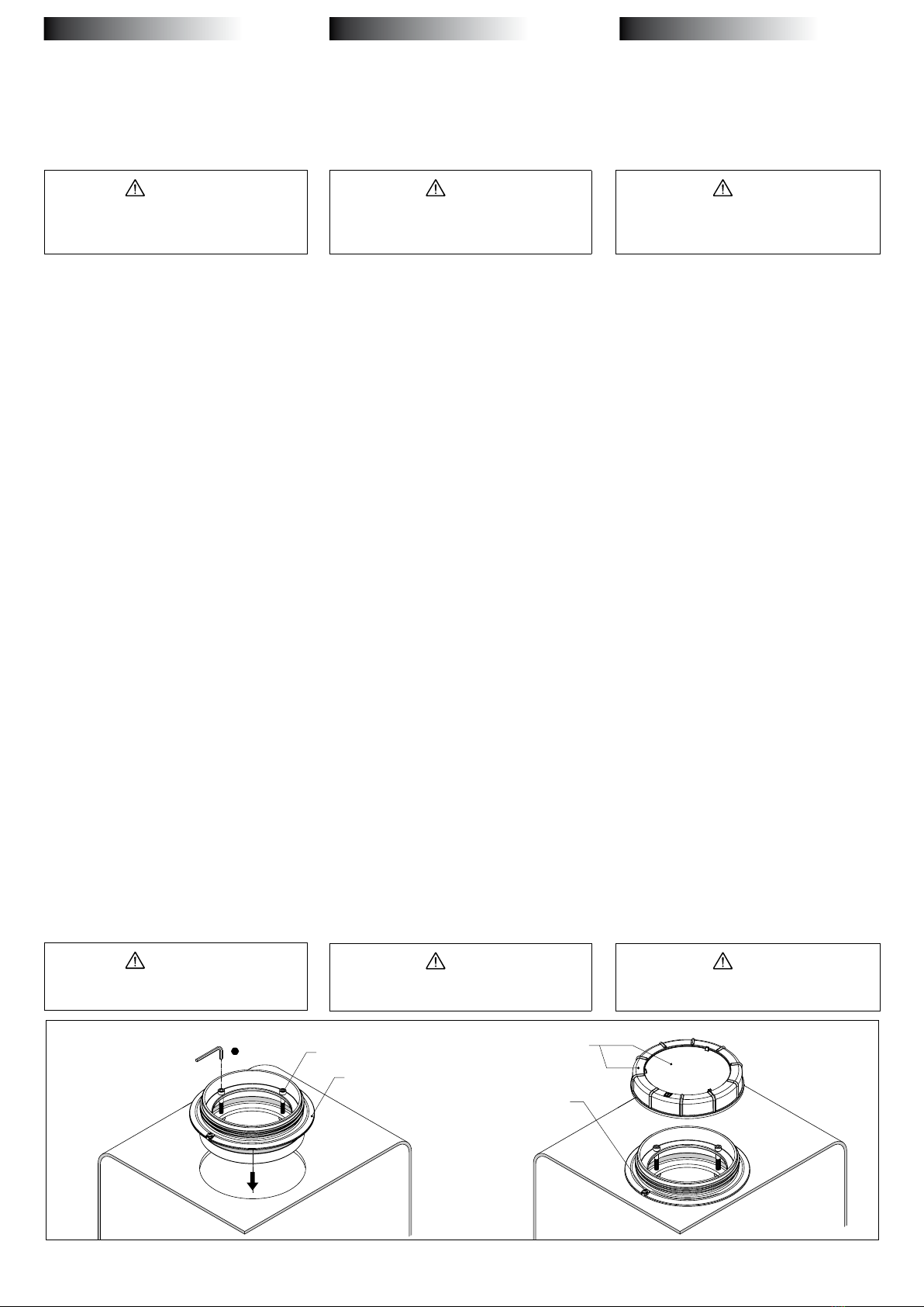
2.3 Pose du bouchon de contrôle
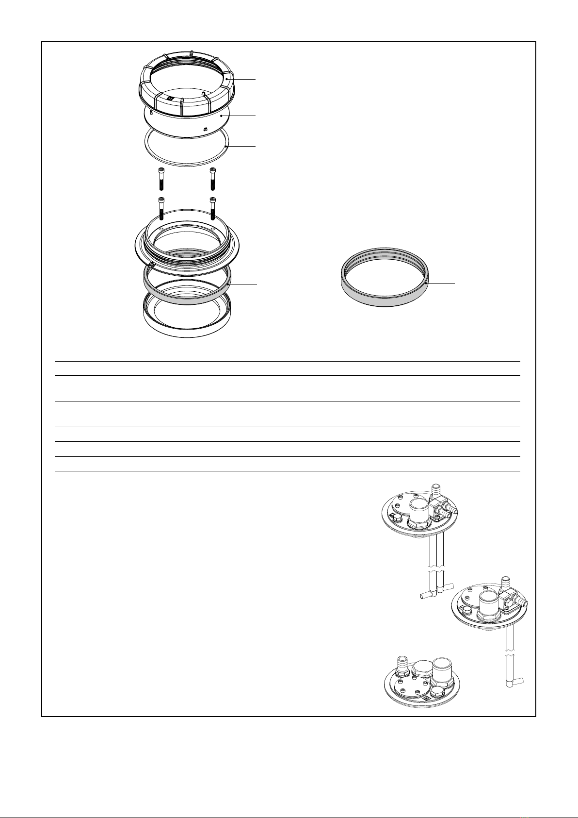
Bride (1)
• Placez la bride (1) dans le trou du réservoir.
• Fixez les 4 vis (2) en les tournant (-1-) chacune
une fois (de gauche à droite) et contrôlez s’il
est toujours possible de tourner manuelle-
ment la bride.
Répétez l’opération jusqu’à ce
qu’il ne soit plus possible de tourner la bride.
• Fixez ensuite les vis une à une en les tournant
quatre fois (-4-)
Raccord à la masse (3)
• La vis (3) sert à raccorder la bride à la masse.
Bouchon (4)
• Vissez le bouchon sur la bride.
REMARQUE !
Vérier l’étanchéité de toutes les connexions
avant le remplissage du réservoir.
1 Introduction
Este manual es aplicable a la tapa de inspección
para depósitos rígidos. El tanque puede estar
hecho de plástico, GRP (plástico reforzado con
vídrio) ó metal y debe tener un grosor mínimo
de pared de 1,5 mm.
NOTA!
Consulte el manual entregado con el tanque
de carburante para ver las instrucciones de
cómo conectarlo.
2 Instalación
2.1 Cortar el agujero para el montaje
de la tapa de inspección
• Cortar el agujero para el montaje de la tapa
de inspección. Coloque la tapa de inspec-
ción en la parte superior del depósito. Si se
utiliza un depósito VETUS, coloque preferen-
temente la tapa de inspección de tal manera
que el conector P se retire al cortar el agujero.
• Corte el agujero en el depósito y retire todas
las rebabas. Utilice preferentemente una sier-
ra de corona (ø 159 mm).
• Limpie el interior de los depósitos antes de
montar la tapa de inspección.
2.2 Junta de goma a emplear
Determine el grosor de la pared del depósito y uti-
lice la junta de goma indicada.
2.3 Montaje de la tapa de inspección
Brida (1)
• Coloque la brida (1) en el agujero del depósito.
• Apriete cada uno de los 4 tornillos (2) una (-1-
) vuelta (en el sentido de las agujas del reloj)
y compruebe si la brida se puede girar fácil-
mente con la mano. Repita este procedimien-
to hasta que la brida no se pueda girar más.
• Después apriete cada uno de los tornillos
otras cuatro (-4-) vueltas.
Conexión de masa (3)
• El tornillo (3) tiene como función poder co-
nectar la brida a la masa.
Tapa (4)
• Atornille la tapa en la brida.
NOTA!
Compruebe el apriete de todas las
conexiones antes de llenar el tanque.
1 Introduzione
Queste istruzioni valgono per coperchio di ispe-
zione per serbatoi rigidi.
Il serbatoio può essere in plastica, GRP o metallo
e deve avere uno spessore minimo di parete di
1,5 mm.
NOTA!
Consultare il manuale fornito con il serbatoio
per carburante per le istruzioni di collega-
mento.
2 Installazione
2.1 Praticare il foro di montaggio per il
tappo d’ispezione
• Praticare il foro di montaggio per il tappo
d’ispezione. Posizionate il tappo d’ispezione
sulla parte superiore del serbatoio. Se usate
un serbatoio VETUS, si consiglia di posizio-
nare il tappo d’ispezione in modo tale che il
tappo P venga rimosso praticando il foro.
• Praticate il foto nel serbatoio e rinitelo li-
mando ogni sbavatura. Si consiglia di usare
una sega per fori (ø159mm).
• Pulite l’interno del serbatoio prima di monta-
re il tappo d’ispezione.
2.2 Guarnizione da applicare
Misurate lo spessore della parete del serbatoio
ed applicate la guarnizione appropriata, secon-
do le indicazioni.
2.3 Montaggio del tappo d’ispezione
Flangia (1)
• Inserite la angia (1) nel foro del serbatoio.
• Avvitate le 4 viti (2) girandole ognuna di un
giro (-1-) (verso destra) e controllate se la an-
gia si può ancora serrare con la mano. Ripete-
te questa azione no a che la angia non si
può più serrare.
• Poi, avvitate ogni vite di altri quattro (-4-) giri.
Collegamento della massa (3).
• La vite (3) serve per collegare la angia alla
massa.
Tappo (4).
• Avvitate il tappo alla angia.
NOTA!
Vericare il serraggio di tutti i collegamenti
prima di riempire il serbatoio.
ESPAÑOL
FRANÇAIS ITALIANO
2
1
4A
4B
4C
ILT120 Service onderdelen Service parts
pos. qty part benaming description
1 1 ILT007 Afdichtrubber, hoogte 16 mm,
voor wanddikte 1,5 tot 4 mm
Rubber seal, height 16 mm,
for wall thickness 1.5 up to 4 mm
2 1 ILT002 Afdichtrubber, hoogte 22 mm,
voor wanddikte 4 tot 10 mm
Rubber seal, height 22 mm,
for wall thickness 4 up to 10 mm
4A 1 ILT004 Dekselmoer Lid nut
4B 1 ILT005 Blindplaat Blind plate
4C 1 ILT006 Pakking Gasket
vetusb.v. FOKKERSTRAAT 571 - 3125 BD SCHIEDAM - HOLLAND
TEL.: +31 0(0)88 4884700 - sales@vetus.nl - www.vetus.com
Printed in the Netherlands
040108.01 2018-09
De blindplaat (4B) van het inspectiedeksel
kan door één van de verschillende aansluit-
kits worden vervangen. Deze aansluitkits
hebben de benodigde aansluitingen voor
een tank voor respectievelijk brandstof (ILT-
CONF38), drinkwater (ILTCOND) of vuilwater
(ILTCONW).
The blind plate (4B) of the inspection co-
ver can be replaced by one of the dierent
connection kits. These connection kits have
the necessary connections for respectively
a tank for fuel (ILTCONF38), drinking water
(ILTCOND) or waste water (ILTCONW).
Die Blindplatte (4B) des Inspektionsdeckels
kann durch ein Anschlusskit ersetzt wer-
den, das in mehreren Versionen lieferbar
ist. Diese Anschlusskits verfügen über die
benötigten Anschlüsse für einen Brennsto-
(ILTCONF38), Trinkwasser- (ILTCOND) bzw.
Abwassertank (ILTCONW).
La plaque aveugle (4B) de la trappe de visite
peut être remplacée par l’un des diérents
kits de raccordement. Ces kits de raccorde-
ment disposent des raccordements néces-
saires pour un réservoir de carburant (ILT-
CONF38), d’eau potable (ILTCOND) ou d’eaux
usées (ILTCONW).
La placa de cobertura (4B) de la tapa de in-
spección se puede reemplazar por uno de
los diferentes kits de conexión. Estos kits de
conexión tienen las conexiones necesarias
para un tanque de combustible (ILTCONF38),
agua potable (ILTCOND) y aguas residuales
(ILTCONW)
La piastra cieca (4B) del coperchio di ispezio-
ne può essere sostituita da uno dei kit di rac-
cordo. Questi kit di raccordo sono dotati dei
diversi raccordi per serbatoi del carburante
(ILTCONF38), dell’acqua potabile (ILTCOND)
o delle acque reue (ILTCONW).
ILTCONF38
ILTCONW
ILTCOND

Other Vetus Tank Equipment manuals

Vetus FTL3808B Quick start guide

Vetus

Vetus FTL3808B Quick start guide

Vetus ILT120B User manual

Vetus

Vetus ILT120B User manual

Popular Tank Equipment manuals by other brands

Esco HURRICANE 20387 instruction manual

Esco

Esco HURRICANE 20387 instruction manual

Elbi DXT Series owner's manual

Elbi

Elbi DXT Series owner's manual

STM DD210 manual

STM

STM DD210 manual

JohnDow Industries JDI-AFT58 user manual

JohnDow Industries

JohnDow Industries JDI-AFT58 user manual

SATA Paint set 10 operating instructions

SATA

SATA Paint set 10 operating instructions

JohnDow Industries JDI-AFT106 Operator's manual

JohnDow Industries

JohnDow Industries JDI-AFT106 Operator's manual

Grundfos El.stirrer f.60l tank Installation and operating instructions

Grundfos

Grundfos El.stirrer f.60l tank Installation and operating instructions

ENCON SAF-T-TUB 01052539 Installation, operation and maintenance manual

ENCON

ENCON SAF-T-TUB 01052539 Installation, operation and maintenance manual

Amtrol THERM-X-TROL ST-5C Series Installation & operation instructions

Amtrol

Amtrol THERM-X-TROL ST-5C Series Installation & operation instructions

Bradley S19-690H Installation

Bradley

Bradley S19-690H Installation

morse 185G Operator's manual

morse

morse 185G Operator's manual

TransTank TopCrop Operator's handbook

TransTank

TransTank TopCrop Operator's handbook

Wilo VBH Series Installation and operating instructions

Wilo

Wilo VBH Series Installation and operating instructions

manuals.online logo
manuals.online logoBrands
  • About & Mission
  • Contact us
  • Privacy Policy
  • Terms and Conditions

Copyright 2025 Manuals.Online. All Rights Reserved.