Bradley S19-690H User manual

P.O. Box 309, Menomonee Falls, WI USA 53052-0309
PHONE 800.BRADLEY (800.272.3539) FAX 262.251.5817
bradleycorp.com
Installation
215-084 Rev. P; ECN 07-527
© 2008 Bradley Corporation
Page 1 of 5 8/25/08
S19-690H
10-Gallon Tank with Eyewash and
Heater Jacket
S19-690HR
Heater Jacket Retrofit for 10-Gallon
Tank
Table of Contents
Pre-Installation Information . . . . . . . . . . . . 2
Installation Instructions. . . . . . . . . . . . . . . . 3
Maintenance and Troubleshooting. . . . . . . 4
Assembly of Components . . . . . . . . . . . . . 5
Parts List . . . . . . . . . . . . . . . . . . . . . . . . . . 5

2
S19-690H, S19-690HR Installation
8/25/08 Bradley Corporation • 215-084 Rev. P; ECN 07-527
WARNING
Read this installation manual completely to ensure proper installation, then file it
with the owner or maintenance department. Compliance and conformity to drain
requirements and other local codes and ordinances is the responsibility of the installer.
Separate parts from packaging and make sure all parts are accounted for before
discarding any packaging material. If any parts are missing, do not begin installation
until you obtain the missing parts.
Flush the water supply lines before beginning installation and after installation is
complete. Test the unit for leaks and adequate water flow. Main water supply to the
eyewash should be “ON” at all times. Provisions shall be made to prevent unauthorized
shutoff.
The ANSI Z358.1 standard requires an uninterruptible supply of flushing fluid at a
minimum 30 PSI (0.21 MPa) flowing pressure. Flushing fluid should be tepid per ANSI
Z358.1.
The inspection and testing results of this equipment should be recorded weekly
to verify proper operation. This equipment should be inspected annually to ensure
compliance with ANSI Z358.1.
Workers who may come in contact with potentially hazardous materials should be
trained regarding the placement and proper operation of emergency equipment per
ANSI Z358.1.
For questions regarding the operation or installation of this product, visit www.
bradleycorp.com or call 800.BRADLEY (800.272.3539).
Product warranties and service parts information may also be found under ”Products”
on our web site at www.bradleycorp.com.
Installation
THIS
SIDE
UP
Packing List
•
•
•
•
P.O.Box309,MenomoneeFalls,WI53051
R
TESTTHISUNITEACHWEEK
Test-operatevalve(s) each week and sign below.
Reportany malfunctions immediately.
Ventil(e)wöchentlich im Testbetriebprüfen, bestätigt
durchUnterschrift. Jegliche Störung sofort melden.
Date
Datum
Date
Signed
Unterschrift
Signe
Date
Date
Date Signed
Signed
Signed
DIESESGERÄT1STWÖCHENTLICHZUPRÜFEN.
ESSAIHEBDOMADAIRE
Testle fonctionnement des valves chaque semaine et
signeen bas. S'il y à quelque chose qui ne va pas fait
unrapport immédiatement.
P.O.BOX309, MENOMONEE FALLS,WI 53052-0309 USA
TEL:1-800-BRADLEY FAX:(262-251-5817)
http://www.bradleycorp.com
114-051
Supplies Required:
• Pipe sealant
• Air pressure equipment or supply
• Sign-mounting hardware

3
Installation S19-690H, S19-690HR
Bradley Corporation • 215-084 Rev. P; ECN 07-527 8/25/08
Installation
Step 1: Assemble Eyewash
1. Assemble the eyewash to the tank outlet with
pipe sealant (by installer) (see page 5).
IMPORTANT: When connecting the
eyewash to the tank outlet, hold the
adapters (items 2 and 3) with a wrench
to prevent stripping. Failure to do
so may damage the seal and cause
leakage. Max. torque 150 in-lbs.
2. Connect the pressure gauge to the adapter
on the pressure side of the tank with pipe
sealant (by installer) (see page 5).
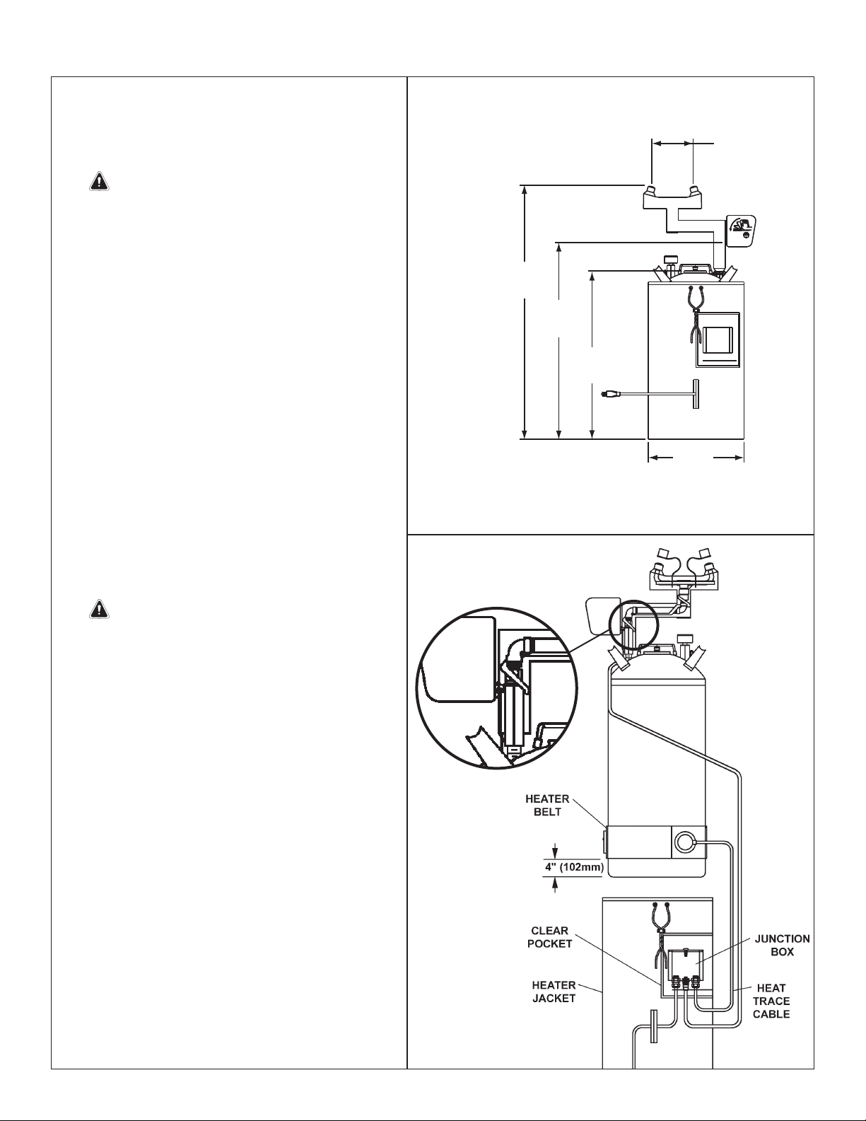
Step 2: Assemble Heater Jacket
1. Secure the pipe insulation and jacket to the
eyewash.
2. Wrap the belt around the tank four inches
from the bottom of the tank; fasten securely.
3. Connect the heat trace cable to the junction
box.
4. Slide the jacket up the side of the tank and
pull the drawstring at the top of the jacket.
5. Place the junction box in the pocket on the
inside of the jacket.
Step 3: Fill tank and pressurize
1. If the tank is pressurized, relieve the tank
pressure by pulling up on the relief tank tab
in the center of the cover until the pressure
gauge reads “0.”
IMPORTANT: DO NOT open the cover
until the pressure gauge reads “0.”
2. Open the tank by pulling up on the wire
handle located on top of the Quicklock
cover. Push down, rotate and remove. Fill
the container with 7 gallons of potable water.
Replace the cover.
3. Pressurize the tank to 95 PSI by applying air
pressure to the tank valve located beneath
the pressure gauge.
NOTE: Relief valve is designed to automatically
vent at 100-130 PSI to prevent the tank from
overpressurizing.
Step 4: Flush tank
1. Discharge the water through the eye wash
and hose spray to flush the system.
2. Refill the tank and pressurize as explained in
Step 3 outlined above.
NOTE: Let unit stand for one hour. If there is a
noticeable pressure drop, repressurize and let
stand for one hour. If problems persist, consult the
Troubleshooting guide found on page 4.
NOTE: This unit will provide at least 15 minutes
of cleansing action. Take the injured person
immediately to a normal emergency station for
additional cleansing and treatment.
3. Plug the heater jacket’s electrical cord into an
electrical outlet.
Back View
BRADLEY
RBradley
14"
(356mm)
24-5/8"
(625mm)
27-3/4"
(705mm)
35-7/8"
(911mm)
6"
(152mm)

4
S19-690H, S19-690HR Installation
8/25/08 Bradley Corporation • 215-084 Rev. P; ECN 07-527
Maintenance
WARNING: Water preservatives protect potable water from bacteria, fungi and algae growth for up to
four months. If a water preservative is not used with this eyewash, it is recommended that the tank
be cleaned weekly or as often as needed. Infection, loss of vision or other serious injury may result
from misuse of this eyewash. DO NOT use expired, cloudy, colored or contaminated solution. DO
NOT open preservative bottle if safety seal is broken. DO NOT save unused solution.
Step 1: Inspect eyewash unit
1. Visually inspect the pressure gauge weekly to ensure the unit is maintaining the proper pressure. If the unit is not
working properly, remove it from the hazard area immediately and refer to the troubleshooting instructions. For further
assistance, contact the Bradley Corporation.
Step 2: Clean eyewash unit
When using potable water only:
1. Empty the tank any time from once per week to once per month, depending on the quality of your water supply. The
manufacturer is not responsible for variations in the water supply.
2. Clean the inside of the tank using warm water and mild soap. Rinse the tank thoroughly with warm water.
3. Refill the eyewash tank following the procedure outlined in Step 3 found on page 3.
When using potable water and water preservative (recommended):
1. Empty the tank at least once every 120 days.
2. Clean the inside of the tank using warm water and mild soap. Rinse the tank thoroughly with warm water.
3. Refill the eyewash tank with potable water and the contents of an 8-ounce bottle of water preservative (refer to the
procedure outlined in Step 3 found on page 3).
• To order potable water preservative, contact your Bradley representative or local distributor and ask for part number
S19-865.
Troubleshooting
1. If pressure relief valve relieves prior to the required pressure, do the following (when in the unpressurized condition):
• Tighten the valve completely into the cap by turning the gray hex head portion of the pressure relief valve
clockwise. Do not use a wrench.
• Pull up on the relief valve ring and ensure that the ring is not preventing the valve from closing completely. Push
on the center pin of the relief valve to ensure that it is completely closed. Repressurize tank to required pressure.
This may have to be done several times to get the valve to seat completely.
2. If the pressurized tank loses pressure over time, check the connections with diluted liquid dish soap or children’s
bubbles to identify the leak location. Tighten the connection slightly and test again.

5
Installation S19-690H, S19-690HR
Bradley Corporation • 215-084 Rev. P; ECN 07-527 8/25/08
Assembly of Components and Parts List
1.1
1
3
5
4
7
6
9
9.1
2
8
10
11
1.3, 1.4
1.3, 1.5
1.22
1.2, 1.21
1 S39-608 1 Tank, 10-Gallon
1.1 204-095 1 Operating Instr. Label
1.2 S44-024 1 Lid Assembly
1.21 269-1410 1 Gasket
1.22 269-1642 1 Relief Valve
1.3 269-1411 2 O-Ring
1.4 269-1516 1 Draw Tube
1.5 269-1515 1 Level Indicator Tube
2 153-429 1 Adapter
3 153-217 1 Adapter
4 169-786 1 Pressure Gauge
5 S27-161 1 Tank Valve Assembly
6 114-051 1 Safety Sign
7 169-043 1 Pipe Plug, 3/8"
8 204-421 1 Emergency Tag
9 S05-116H 1 Eyewash Assembly, Heated
9.1 107-371 2 Tethered Dust Cover
10 S83-167 1 Junction Box Assembly
11 269-1669 1 Heater Jacket
Item Part No. Qty Description Item Part No. Qty Description
S45-2410 includes Items 1.21, 1.3
Other manuals for S19-690H
3
This manual suits for next models
1
Table of contents
Popular Tank Equipment manuals by other brands

Trane
Trane RSDT1000F0AA Installation, operation and maintenance

WELBA
WELBA WTS-200 Installation and operating instructions

Regulus
Regulus PS2F 3000 N25 Installation and operation manual

Sears
Sears Kenmore 390.291195 owner's manual

Vmac
Vmac A500245 installation manual

Regulus
Regulus PS 500 E Assembly, installation and operation instructions