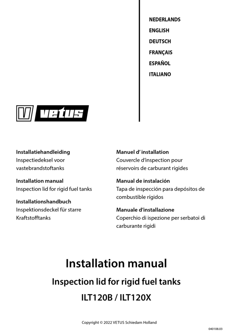
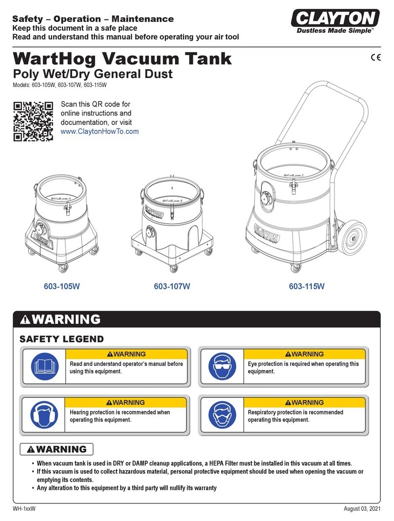
Vetus FTL3808B Quick start guide

040106.04
NEDERLANDS 3
ENGLISH 9
DEUTSCH 15
FRANÇAIS 21
ESPAÑOL 27
ITALIANO 33
Copyright © 2020 Vetus b.v. Schiedam Holland
Installatie instructies en
eigenaarshandleiding
Aansluitkit voor brandstoftanks
Installation instructions and
owner's manual
Connection kit for fuel tanks
Einbauanleitung und
Handbuch für den Eigentümer
Anschlußbausätze für Kraftstotank
Instructions d’installation et
mode d’emploi destiné au propriétaire
Kits de raccordement pour
des réservoirs de carburant
Instrucciones de instalación y
manual del propietario
Estuches para tanques de carburant
Istruzioni per l’installazione e
manuale per l’utente
Kit di raccordo per serbatoi per carburante
Connection kit for fuel tanks
FTL3808B - FTL3810B - FTL3815B
FTL5108B - FTL5110B - FTL5115B

2040106.04 Connection kit for fuel tanks vetus®
Inhoud Content
Inhalt Sommaire
Índice Indice
1 Inleiding . . . . . . . . . . . . . . . . . . . . . . . . . . . . . . . . . . . . . . . . . . . . . . . 3
2 Installatie . . . . . . . . . . . . . . . . . . . . . . . . . . . . . . . . . . . . . . . . . . . . . . 3
2.1 Algemeen . . . . . . . . . . . . . . . . . . . . . . . . . . . . . . . . . . . . . . . . . . . . . . 3
2.2 Aanbrengen van montagegat aansluitdeksel . . . . . . . . . . . . . 4
2.3 Toe te passen afdichtrubber . . . . . . . . . . . . . . . . . . . . . . . . . . . . . 5
2.4 Montage aansluitdeksel voor 8 en 10 mm toevoer- en
retourleiding . . . . . . . . . . . . . . . . . . . . . . . . . . . . . . . . . . . . . . . . . . . 5
2.5 Montage aansluitdeksel voor 15 mm toevoer- en
retourleiding . . . . . . . . . . . . . . . . . . . . . . . . . . . . . . . . . . . . . . . . . . . 6
2.6 Aansluiten van de tank. . . . . . . . . . . . . . . . . . . . . . . . . . . . . . . . . . 7
2.7 Controle . . . . . . . . . . . . . . . . . . . . . . . . . . . . . . . . . . . . . . . . . . . . . . . . .
3 Winterklaar maken . . . . . . . . . . . . . . . . . . . . . . . . . . . . . . . . . . . . . 8
4 Onderhoud . . . . . . . . . . . . . . . . . . . . . . . . . . . . . . . . . . . . . . . . . . . . 8
5 Technische gegevens. . . . . . . . . . . . . . . . . . . . . . . . . . . . . . . . . . . 8
1 Einleitung. . . . . . . . . . . . . . . . . . . . . . . . . . . . . . . . . . . . . . . . . . . . . 15
2 Installation. . . . . . . . . . . . . . . . . . . . . . . . . . . . . . . . . . . . . . . . . . . . 15
2.1 Allgemeines . . . . . . . . . . . . . . . . . . . . . . . . . . . . . . . . . . . . . . . . . . . 15
2.2 Schneiden des Loches für den Anschlussdeckel. . . . . . . . . . 16
2.3 Zu verwendender Dichtgummiring . . . . . . . . . . . . . . . . . . . . . 17
2.4 Montage des Anschlussdeckels für eine 8 und 10mm
Zufuhr - und Rücklaueitung . . . . . . . . . . . . . . . . . . . . . . . . . . . 17
2.5 Montage der Verbinder Abdeckung für eine 15mm
Zufuhr - und Rücklaueitung . . . . . . . . . . . . . . . . . . . . . . . . . . . 18
2.6 Anschließen des Tanks . . . . . . . . . . . . . . . . . . . . . . . . . . . . . . . . . 19
2.7 Kontrolle . . . . . . . . . . . . . . . . . . . . . . . . . . . . . . . . . . . . . . . . . . . . . . . . .
3 Winterfest machen . . . . . . . . . . . . . . . . . . . . . . . . . . . . . . . . . . . . 20
4 Wartung . . . . . . . . . . . . . . . . . . . . . . . . . . . . . . . . . . . . . . . . . . . . . . 20
5 Technische Daten . . . . . . . . . . . . . . . . . . . . . . . . . . . . . . . . . . . . . 20
1 Introducción . . . . . . . . . . . . . . . . . . . . . . . . . . . . . . . . . . . . . . . . . . 27
2 Instalación . . . . . . . . . . . . . . . . . . . . . . . . . . . . . . . . . . . . . . . . . . . . 27
2.1 Generalidades . . . . . . . . . . . . . . . . . . . . . . . . . . . . . . . . . . . . . . . . . 27
2.2 Cortar el agujero para la tapa del conector . . . . . . . . . . . . . . 28
2.3 Junta de goma a emplear . . . . . . . . . . . . . . . . . . . . . . . . . . . . . . 29
2.4 Instalación de la tapa del conector para mangueras de
aspiración y retorno de 8 y 10 mm . . . . . . . . . . . . . . . . . . . . . . 29
2.5 Instalación de la tapa del conector para mangueras de
aspiración y retorno de 15 mm . . . . . . . . . . . . . . . . . . . . . . . . . 30
2.6 Conexión del depósito . . . . . . . . . . . . . . . . . . . . . . . . . . . . . . . . . 31
2.7 Comprobación . . . . . . . . . . . . . . . . . . . . . . . . . . . . . . . . . . . . . . . . 31
3 Preparación para el invierno. . . . . . . . . . . . . . . . . . . . . . . . . . . 32
4 Mantenimiento . . . . . . . . . . . . . . . . . . . . . . . . . . . . . . . . . . . . . . . 32
5 Datos técnicos . . . . . . . . . . . . . . . . . . . . . . . . . . . . . . . . . . . . . . . . 32
1 Introduction . . . . . . . . . . . . . . . . . . . . . . . . . . . . . . . . . . . . . . . . . . . 9
2 Installation. . . . . . . . . . . . . . . . . . . . . . . . . . . . . . . . . . . . . . . . . . . . . 9
2.1 General . . . . . . . . . . . . . . . . . . . . . . . . . . . . . . . . . . . . . . . . . . . . . . . . 9
2.2 Cutting the hole for the connector lid . . . . . . . . . . . . . . . . . . . 10
2.3 Rubber seal to be applied . . . . . . . . . . . . . . . . . . . . . . . . . . . . . . 11
2.4 Installation of connector lid for 8 and 10 mm supply and
return pipe . . . . . . . . . . . . . . . . . . . . . . . . . . . . . . . . . . . . . . . . . . . . 11
2.5 Installation of connector lid for 15 mm supply and return
pipe . . . . . . . . . . . . . . . . . . . . . . . . . . . . . . . . . . . . . . . . . . . . . . . . . . 12
2.6 Connecting the tank . . . . . . . . . . . . . . . . . . . . . . . . . . . . . . . . . . . 13
2.7 Check . . . . . . . . . . . . . . . . . . . . . . . . . . . . . . . . . . . . . . . . . . . . . . . . . 13
3 Preparing for winter. . . . . . . . . . . . . . . . . . . . . . . . . . . . . . . . . . . 14
4 Maintenance. . . . . . . . . . . . . . . . . . . . . . . . . . . . . . . . . . . . . . . . . . 14
5 Technical Data . . . . . . . . . . . . . . . . . . . . . . . . . . . . . . . . . . . . . . . . 14
1 Introduction . . . . . . . . . . . . . . . . . . . . . . . . . . . . . . . . . . . . . . . . . . 21
2 Installation. . . . . . . . . . . . . . . . . . . . . . . . . . . . . . . . . . . . . . . . . . . . 21
2.1 Généralités . . . . . . . . . . . . . . . . . . . . . . . . . . . . . . . . . . . . . . . . . . . . 21
2.2 Perçage du trou pour le couvercle du connecteur . . . . . . . . 22
2.3 Joint d’étanchéité à mettre en place. . . . . . . . . . . . . . . . . . . . . 23
2.4 Installation du couvercle du connecteur pour les tuyaux
d’arrivée et de retour de 8 et 10 mm . . . . . . . . . . . . . . . . . . . . 23
2.5 Installation du couvercle du connecteur pour les tuyaux
d’arrivée et de retour de 15 mm. . . . . . . . . . . . . . . . . . . . . . . . . 24
2.6 Raccordement du réservoir. . . . . . . . . . . . . . . . . . . . . . . . . . . . . 25
2.7 Contrôle . . . . . . . . . . . . . . . . . . . . . . . . . . . . . . . . . . . . . . . . . . . . . . 25
3 Remisage pour l’hiver . . . . . . . . . . . . . . . . . . . . . . . . . . . . . . . . . 26
4 Entretien. . . . . . . . . . . . . . . . . . . . . . . . . . . . . . . . . . . . . . . . . . . . . . 26
5 Fiche technique . . . . . . . . . . . . . . . . . . . . . . . . . . . . . . . . . . . . . . . 26
1 Introduzione. . . . . . . . . . . . . . . . . . . . . . . . . . . . . . . . . . . . . . . . . . 33
2 Installazione . . . . . . . . . . . . . . . . . . . . . . . . . . . . . . . . . . . . . . . . . . 33
2.1 Generalità . . . . . . . . . . . . . . . . . . . . . . . . . . . . . . . . . . . . . . . . . . . . . 33
2.2 Tagliare il foro per il coperchio del connettore . . . . . . . . . . . 34
2.3 Guarnizione da applicare. . . . . . . . . . . . . . . . . . . . . . . . . . . . . . . 35
2.4 Installazione del coperchio connettore per tubo di
alimentazione e ritorno di 8 e 10 mm . . . . . . . . . . . . . . . . . . . 35
2.5 Installazione del coperchio connettore per tubo
alimentazione e ritorno 15 mm . . . . . . . . . . . . . . . . . . . . . . . . . 36
2.6 Collegamento del serbatoio . . . . . . . . . . . . . . . . . . . . . . . . . . . . 37
2.7 Controlli. . . . . . . . . . . . . . . . . . . . . . . . . . . . . . . . . . . . . . . . . . . . . . . 37
3 Preparazione per il rimessaggio . . . . . . . . . . . . . . . . . . . . . . . 38
4 Manutenzione . . . . . . . . . . . . . . . . . . . . . . . . . . . . . . . . . . . . . . . . 38
5 Dati tecnici. . . . . . . . . . . . . . . . . . . . . . . . . . . . . . . . . . . . . . . . . . . . 38
6 Hoofdafmetingen . . . . . . . . . . . . . . . . . . . . . . . . . . . . . . . . . . . . . 40
6 Hauptabmessungen . . . . . . . . . . . . . . . . . . . . . . . . . . . . . . . . . . 40
6 Dimensiones principales . . . . . . . . . . . . . . . . . . . . . . . . . . . . . . 40
6 Principal dimensions . . . . . . . . . . . . . . . . . . . . . . . . . . . . . . . . . . 40
6 Dimensions principales. . . . . . . . . . . . . . . . . . . . . . . . . . . . . . . . 40
6 Dimensioni principali . . . . . . . . . . . . . . . . . . . . . . . . . . . . . . . . . 40
040106.04 3
vetus® Connection kit for fuel tanks
1 Inleiding
Deze handleiding geldt voor de aansluitkit voor de Vetus (vaste)
kunststof dieselbrandstoftanks.
Deze tanks voldoen aan de eisen volgens ISO 21487.
Bij de installatie van een brandstoftank dienen de Europese Richtlijn
Pleziervaartuigen (RCD, 2013/53/EU) en eventuele nationale wetge-
ving in acht te worden genomen. Pas de norm ISO 10088 toe als lei-
draad.
- De twee tanks worden gevuld en gebruikt als één grote tank.
In het geval van een twee-motorige installatie verdient het de hoog-
ste aanbeveling om een aparte tank voor elke motor te installeren.
De brandstoftoevoerleiding dient zo te worden uitgevoerd dat in
geval van nood elk van de tanks brandstof kan leveren aan beide
motoren.
Elke tank moet voorzien zijn van een vulaansluiting en een ontluch-
ting.
- De twee tanks kunnen onafhankelijk van elkaar worden gevuld
en gebruikt maar kunnen ook als één grote tank worden gebruikt.
min. 30 cm
2 Installatie
2.1 Algemeen
Houdt bij het kiezen van een plaats van de tank en een plaats voor de
dekvuldop met het volgende rekening:
De vulslang moet zo kort mogelijk zijn, moet continu van de dekdop
naar de tank aopen en zo recht mogelijk zijn.
Let op!
Stel de tank zodanig op dat de plug P zich aan de bovenzijde
van de tank bevindt. (Raadpleeg de afmetingentekeningen op
pagina 40 voor de plaats van plug P.)
WaarschuWing
Plaats de vuldop nooit in een afgesloten ruimte, gemorste
brandstof kan dan in het schip terechtkomen!
In plaats van slechts één tank is het ook mogelijk om de totaal beno-
digde capaciteit over twee of meer tanks te verdelen.
Afhankelijk van de wijze van aansluiten zijn er twee mogelijkheden:
Voor afmetingen zie tekeningen op blz. 40. Voor alle afmetingen gel-
den toleranties van + of - 2% !
NEDERLANDS

4040106.04 Connection kit for fuel tanks vetus®
Opstelling
Stel de tank zodanig op dat deze goed toegankelijk is voor inspectie.
De tank dient steeds boven het maximale niveau van het bilgewater
te worden opgesteld.
Zorg ook voor voldoende vrije ruimte aan de bovenzijde van de tank
in verband met de slangaansluitingen, deze moeten tijdens de mon-
tage goed toegankelijk zijn. Voor ventilatie dient de tank rondom ca.
1 cm vrij te blijven van schotten of andere tanks.
Zorg voor een voldoende stevige fundatie om te tank op te stellen en
goed vast te kunnen zetten.
De afmetingen van een tank nemen in geringe mate toe als deze
gevuld is. Houdt hiermee rekening met het vastzetten van de tank.
Zet de tank vast met de bevestigingsbanden uit de aansluitkit; deze
staan uitzetten van de tank toe.
Montage in zeilschepen
Houd rekening bij het monteren, dat de vulslang te allen tijde aan
dezelfde boordzijde gemonteerd dient te worden als de tank.
Dit voorkomt mogelijk een te grote overdruk bij varen onder helling.
2.2 Aanbrengen van montagegat aansluitdeksel
Plaats het aansluitdeksel in de bovenzijde van de tank. Indien een
VETUS tank wordt gebruikt plaats dan het aansluitdeksel bij voorkeur
zo dat de plug P wordt verwijdert bij het aanbrengen van het gat.
Breng het gat in de tank aan en werk het braambrij af.
Let op
Gebruik een gatenzaag (ø114 mm) om een nauwkeurig rond
gat te maken. Dit is noodzakelijk om een goede afdichting te
verkrijgen. Een gatenzaag ø114 mm is leverbaar, Vetus art.
code VSAW114.
Reinig de binnenzijde van de tank alvorens het aansluitdeksel te
monteren.
P
ø 114 mm (4 1/2˝)
MIN. 135 mm
W
F
F
W
Verdeel de tanks, dus het gewicht, gelijkmatig over het schip.
(F = Brandstof (Fuel) en W = Water)
± 30 mm
70 mm
70 mm

040106.04 5
vetus® Connection kit for fuel tanks
• Aansluitdeksel (5)
Plaats het aansluitdeksel (5) in het gat van de tank.
Draai de 3 schroeven (6) ieder één (-1-) omwenteling vast (rechts-
om) en test of het deksel nog eenvoudig met de hand te verdraai-
en is.
Herhaal dit tot het deksel niet meer te verdraaien is. Controleer of
de vulaansluiting in de gewenste richting wijst. Draai hierna ie-
dere schroef nog drie (-3-) omwentelingen vast.
6
4
5
10
11
10 - 15 mm
5
8
7
1
4
6
3
8
2
9
8
• Brandstofaanzuigleiding (1)
Monteer de knelkoppeling (7) met de afdichtring (8) in het deksel,
maak de aanzuigleiding op de juiste lengte - de onderzijde moet
zich 10 - 15 mm van de onderzijde van de tank bevinden- en mon-
teer de aanzuigleiding in de knelkoppeling.
• Brandstofretour (2)
Monteer de slangpilaar met de afdichtring (8) in het deksel.
Monteer de meegeleverde blindplug (9) als de brandstofretour-
aansluiting niet gebruikt wordt.
• Ontluchting (3)
Monteer de slangpilaar met de afdichtring (8).
• Massa-aansluiting (4)
Monteer de contacttong.
• Deksel / gever voor tankniveaumeter (10)
Monteer het deksel of monteer een gever voor de tankniveaume-
ter; pas altijd de pakking (11) toe.
2.4 Montage aansluitdeksel voor 8 en 10 mm toe-
voer- en retourleiding
Let op!
Controleer de dichtheid van alle verbindingen alvorens de
tank te vullen.
2.3 Toe te passen afdichtrubber
Bepaal de wanddikte van de tank en pas het aangegeven afdichtrub-
ber toe.
T
T = 1.5 - 4 mm
15 mm
21 mm
T = 4 - 10 mm
10 mm
10 mm
8 mm
8 mm
NEDERLANDS

6040106.04 Connection kit for fuel tanks vetus®
10
11
5
6
3
8
4
7
1
8
10 - 15 mm
2.5 Montage aansluitdeksel voor 15 mm toevoer-
en retourleiding
• Brandstofretour (2)
Monteer de knelkoppeling (7) met de afdichtring (8) in het aan-
sluitdeksel, maak de retourleiding (2) op de juiste lengte.
Let op!
De retourleiding bestaat uit twee delen; de uitstroomopening
van het bochtstuk moet zich ca. 20 mm van de onderzijde van
de tank bevinden en moet van de brandstofaanzuigbuis zijn af-
gekeerd.
Monteer de retourleiding in de knelkoppeling.
7
2
8
ca. 20 mm
5
6
4
• Aansluitdeksel (5)
Plaats het aansluitdeksel (5) in het gat van de tank.
Draai de 3 schroeven (6) ieder één (-1-) omwenteling vast (rechts-
om) en test of het deksel nog eenvoudig met de hand te verdraai-
en is.
Herhaal dit tot het deksel niet meer te verdraaien is. Controleer of
de vulaansluiting in de gewenste richting wijst. Draai hierna ie-
dere schroef nog drie (-3-) omwentelingen vast.
• Brandstofaanzuigleiding (1)
Monteer de knelkoppeling (7) met de afdichtring (8) in het deksel,
maak de aanzuigleiding op de juiste lengte - de onderzijde moet
zich 10 - 15 mm van de onderzijde van de tank bevinden- en mon-
teer de aanzuigleiding in de knelkoppeling.
• Ontluchting (3)
Monteer de slangpilaar met de afdichtring (8).
• Massa-aansluiting (4)
Monteer de contacttong.
• Deksel / gever voor tankniveaumeter (10)
Monteer het deksel of monteer de gever voor de tankniveaume-
ter; pas altijd de pakking (11) toe.
Let op!
Controleer de dichtheid van alle verbindingen alvorens de
tank te vullen.
15 mm
15 mm
15 mm

040106.04 7
vetus® Connection kit for fuel tanks
11
10
7
6
13
8
12
7
9
8
8 mm
10 mm
15 mm
3
4
3
4
2
2
1
1
5
5
1 Brandstofaanzuig
2 Brandstofretour
3 Vulaansluiting
4 Ontluchting (Slangpilaar)
5 Aardeaansluiting
6 Vulslang, ø 38 / ø 51 mm
7 Ontluchtingsnippel
8 Ontluchtingsleiding, ø16mm
9 Zwanenhals
10 Geurlter
11 Brandstofoverloop
12 Ontluchtings- /
overloopleiding, ø 16 mm
13 Vuldop
2.7 Controle
Controleer na installatie het systeem op dichtheid.
Afpersdruk 20 kPa (0,2 bar).
Sticker
Breng de rode sticker voor 'Diesel fuel tank' aan op de tank, zodanig
dat de tekst leesbaar is en breng ook de inhoudssticker aan.
Fresh water tank
• Drinking water safe• Meets KTW standard
• P max. 30 kPa (0.3 bar | 4.35 psi)
• Tank capacity of:
AT147583W.VE
Quality product by vetus, Schiedam
Designed and made in the Netherlands Excellent
warranty Worldwide
network
Diesel fuel tank
• According to ISO 21487 • 0613
AT147583F.VE
• Max. test pressure 30 kPa (0.3 bar | 4.35 psi)
• Tank capacity of:
• Max. 100 °C
• Max. ll-up height 3.5 m
Quality product by vetus,Schiedam
Designed and made in the Netherlands Excellent
warrantyWorldwide
network
Waste water tank
• According to ISO 8099
• P max. 30 kPa (0.3 bar | 4.35 psi) • 0613
• Tank capacity of:
AT147583B.VE
Quality product by vetus,Schiedam
Designed and made in the Netherlands Excellent
warrantyWorldwide
network
42 litres
9.2 Imp.Gal. | 11.1 US Gal.
61 litres
13.4 Imp.Gal. | 16.1 US Gal.
88 litres
19.4 Imp.Gal. | 23.2 US Gal.
170 litres
37.4 Imp.Gal. | 44.9 US Gal.
215 litres
47.3 Imp.Gal. | 56.8 US Gal.
335 litres
73.7 Imp.Gal. | 88.5 US Gal.
110 litres
24.2 Imp.Gal. | 29 US Gal.
390 litres
85.8 Imp.Gal. | 103 US Gal.
xx litres
xx.x Imp.Gal. | xx.x US Gal.
xx litres
xx.x Imp.Gal. | xx.x US Gal.
100 litres
22 Imp.Gal. | 26.4 USGal.
xx litres
xx.x Imp.Gal. | xx.x US Gal.
137 litres
30.1 Imp.Gal. | 36.2 US Gal.
xx litres
xx.x Imp.Gal. | xx.x US Gal.
AT147583A.VE
Diesel fuel tank
• According to ISO 21487 • 0613
AT147583F.VE
• Max. test pressure 30 kPa (0.3 bar | 4.35 psi)
• Tank capacity of:
• Max. 100 °C
• Max. ll-up height 3.5 m
Quality product by vetus, Schiedam
Designed and made in the Netherlands Excellent
warranty Worldwide
network
xx litres
xx.x Imp.Gal. | xx.x US Gal.
tip!
Via de ontluchtingsnippel kunnen onaangename geuren vrijkomen.
Dit is te voorkomen door het installeren van een actief koollter
(Vetus Geurlter (10) ) in de ontluchtingsleiding (8). Raadpleeg de
bijbehorende handleiding voor installatie van het Vetus geurlter.
• Ontluchtingsleiding
Monteer de ontluchtingsleiding (8), pas hiervoor een brandstof-
bestendige slang met een inwendige diameter van 16 mm toe.
De ontluchtingsleiding dient, vanaf de tank gezien, voortdurend
in hoogte oplopend te worden gemonteerd.
• Brandstoftoevoer en retour
Sluit de brandstoftoevoer (1) en de brandstofretour leiding (2) aan
op de respectievelijke ttingen.
Monteer alle slangverbindingen met 2 RVS slangklemmen!
Alle metalen delen van het brandstofsysteem moeten geaard wor-
den om vonken ten gevolge statische elektriciteit te voorkomen.
Sluit een aardedraad aan op de contacttong (5) op het aansluitdek-
sel. Sluit ook een aardedraad aan op de dekvuldop. Toe te passen
draaddoorsnede tenminste 1 mm2, kleur van de isolatie groen/geel.
2.6 Aansluiten van de tank
• Vuldop
Monteer de vuldop (13).
tip!
Via de vuldop kan tijdens het vullen brandstof overlopen en op
het dek terechtkomen. Dit is te voorkomen door het installeren
van een Vetus brandstofoverloop (11) tussen vuldop (13) en de
tank. Raadpleeg de bijbehorende handleiding voor installatie
van de Vetus brandstofoverloop.
• Vulslang
Monteer een vulslang (6) tussen de vuldop en de tank, pas hier-
voor een brandstofbestendige slang met een inwendige diame-
ter van 38 resp. 51 mm toe. Installeer deze slang zodanig dat zo-
wel de tank als de vuldop niet mechanisch worden belast.
• Ontluchtingsnippel
Monteer de ontluchtingsnippel (7), zo hoog mogelijk, boven het
niveau van de bovenzijde van de tank.
WaarschuWing
Kies een zodanige plaats voor de ontluchting dat uitstromen-
de brandstof of brandstofdamp niet in het schip terecht komt!
NEDERLANDS

8040106.04 Connection kit for fuel tanks vetus®
3 Winterklaar maken
Het is raadzaam de brandstoftank tijdens de winterperiode volledig
te vullen met brandstof om condensatie tegen te gaan.
Waterdruppels in brandstof zijn de ideale transporteurs van vuil en
roest door nauwe leidingen. Een volle brandstoftank voorkomt bac-
terievorming in de tank.
Type ATANK42 ATANK61 TANK88 ATANK110 ATANK137 ATANK170 ATANK215 ATANK335 ATANK390
Inhoud 42 61 88 110 137 170 215 335 390 liter *)
Gewicht 3,0 4,0 6,7 7,5 9,25 11,4 13,6 25,8 26,6 kg *)
Max. druk 30 kPa (0,3 bar)
Materiaal
mMPE (Metallocene Medium Density Polyethylene),
kleur : blauw
*) Opgegeven zijn de nominale waarden voor inhoud en gewicht. Geringe afwijkingen zijn mogelijk.
5 Technische gegevens
Type voor vulslang voor aanzuigslang voor retourslang voor ontluchting
FTL3808B ø 38 mm ø 8 mm ø 8 mm ø 16 mm
FTL3810B ø 38 mm ø 10 mm ø 10 mm ø 16 mm
FTL3815B ø 38 mm ø 15 mm ø 15 mm ø 16 mm
FTL5108B ø 51 mm ø 8 mm ø 8 mm ø 16 mm
FTL5110B ø 51 mm ø 10 mm ø 10 mm ø 16 mm
FTL5115B ø 51 mm ø 15 mm ø 15 mm ø 16 mm
Afmetingen ttingen:
4 Onderhoud
- Controleer regelmatig de ontluchtingsnippel en reinig de zeef
van de ontluchtingsnippel indien noodzakelijk.
- Controleer jaarlijks de slangen en slangverbindingen op moge-
lijke lekkage en monteer nieuwe slangen en/of slangklemmen
indien noodzakelijk.
- Controleer tevens de tank op beschadigingen ten gevolge van
schavielen. Vervang een beschadigde tank onmiddellijk.
Aansluiting voor tankniveausensor:
voor sensor met een 5 gats SAE ens.
8 mm
10 mm
15 mm
max. 400 mm
max. 800 mm
max. 900 mm
M5
68°
68°
72°
72°
80°
ø 42 mm
P.c.d. 54 mm

040106.04 9
vetus® Connection kit for fuel tanks
1 Introduction
This manual is for the Vetus (rigid) plastic diesel fuel tanks.
These tanks comply with the requirements according to ISO 21487.
When installing a fuel tank, the European Recreational Craft Direc-
tive (RCD, 2013/53/EU) and any national legislation must be ob-
served. Use the ISO 10088 standard as a guide.
- The two tanks are lled and used as one large tank.
In the case of a twin-engine installation, it is strongly recommended
that a separate tank is installed for each engine.The fuel supply pipes
should be tted in such a way that in the case of an emergency, either
of the tanks can supply both engines.
Each tank must be tted with a ller connector and air-relief.
- The two tanks can be lled and used independently but they can
also be used as one large tank.
min. 30 cm
(12”)
2 Installation
2.1 General
When choosing a location for the tank and a place for the deck ller
cap, take the following into account:
The ller hose must be kept as short as possible, it must run continu-
ously to the tank and be as straight as possible.
note
Position the tank in such a way that the plug P is on the top side
of the tank. Consult the diagrams on page 40 for placement of
plug P.
Warning
Never t the ller cap in an enclosed space, spilled fuel could
then enter the ship!
Instead of just one tank, it is also possible to distribute the total ca-
pacity required over two or more tanks.
Depending on the way connected, there are two possibilities:
See the drawings on page 40 for dimensions. Tolerances of + or - 2%
apply to all dimensions!
ENGLISH

10 040106.04 Connection kit for fuel tanks vetus®
Positioning
Install the tank in such a way that it is easily accessible for inspection.
The tank should always be installed above the maximum bilge water
level.
Also ensure that there is sucient free space at the top of the tank
for the hose connection. This connection must be easily reached dur-
ing installation. For ventilation, the tank should have a free space of
about 1 cm (3/8”). from bulkheads or other tanks.
Make sure the tank has a suciently secure foundation on which to
install it and secure it properly.
The dimensions of the tank will increase a little when it is lled.
Take this into account when xing the tank.
Fix the tank securely with the tting straps from the installation kit;
these will accommodate the expansion of the tank.
Fitting in sailing boats
When tting remember that the ller hose must always be posi-
tioned on the same side of the boat as the tank.
This prevents too high a pressure from possibly occurring in the tank
when sailing heeled.
2.2 Cutting the hole for the connector lid
Position the connector lid on the top face of the tank. If a VETUS tank
is used, then it should be tted with plug P on the top and the con-
nector lid should preferably be located so that plug P is removed
when the hole is cut.
Cut the hole in the tank and remove all burrs.
note!
Drill an exactly round hole using a hole saw (ø114 mm, 4 1/2”
diam.). This is essential in order to achieve proper sealing. A
ø 114 mm hole saw is available from Vetus under art. code
VSAW114.
Clean the inside of the tank before tting the connector lid.
P
ø 114 mm (4 1/2˝)
MIN. 135 mm
W
F
F
W
Distribute the tanks, and thus the weight, evenly over the ship (F=
Fuel, W = Water).
± 30 mm
70 mm
70 mm

040106.04 11
vetus® Connection kit for fuel tanks
• Connector lid (5)
Position connector lid (5) into the hole in the tank.
Tighten each of the 3 screws (6) one (-1-) revolution (clockwise)
and check if the lid can be rotated easily by hand.
Repeat this until the lid can’t be rotated anymore. Check that the
inlet connection is facing in the required direction. Then tighten
each of the screws another three (-3-) revolutions.
• Fuel supply line (1)
Fit the compression coupler (7) with sealing washer (8) into the
lid, cut the suction pipe to the correct length - the lower end of
the pipe should be 10 - 15 mm (3/8- 5/8”) above the bottom of the
tank - and t the suction pipe in the compression coupler.
• Fuel return (2)
Fit the hose pillar with sealing washer (8) into the lid.
Fit the supplied blind plug (9) if the fuel return connection is not
being used.
• Tank vent (3)
Fit the hose pillar with the sealing washer (8).
• Earth connection (4)
Fit the terminal tag.
• Blanking plate/sender for fuel level indicator (10)
Fit either the blanking plate or a fuel level indicator sender; always
use the gasket (11).
2.4 Installation of connector lid for 8 and 10 mm
supply and return pipe
note!
Check the tightness of all connections before lling the tank.
2.3 Rubber seal to be applied
Determine the thickness of the wall of the tank and use the indicated
rubber seal.
6
4
5
10
11
10 - 15 mm
5
8
7
1
4
6
3
8
2
9
8
T
T = 1.5 - 4 mm
(1/16”- 5/32”)
(5/32”- 3/8”)
15 mm (9/16”)
21 mm (13/16”)
T = 4 - 10 mm
10 mm
10 mm
8 mm
8 mm
ENGLISH

12 040106.04 Connection kit for fuel tanks vetus®
10
11
5
6
3
8
4
7
1
8
10 - 15 mm
2.5 Installation of connector lid for 15 mm supply
and return pipe
• Fuel return (2)
Fit the compression coupler (7) with sealing washer (8) into the lid,
cut the return pipe (2) to the correct length.
note!
The return pipe consists of two parts; the end of the curved low-
er portion should be located about 20 mm (3/4”) from the tank
bottom and face away from the fuel suction pipe.
Fit the return pipe in the compression coupler.
7
2
8
ca. 20 mm
5
6
4
• Connector lid (5)
Position connector lid (5) into the hole in the tank.
Tighten each of the 3 screws (6) one (-1-) revolution (clockwise)
and check if the lid can be rotated easily by hand.
Repeat this until the lid can’t be rotated anymore. Check that the
inlet connection is facing in the required direction. Then tighten
each of the screws another three (-3-) revolutions.
• Fuel supply line (1)
Fit the compression coupler (7) with sealing washer (8) into the
lid, cut the suction pipe to the correct length - the lower end of
the pipe should be 10 - 15 mm (3/8- 5/8”) above the bottom of the
tank - and t the suction pipe in the compression coupler.
• Tank vent (3)
Fit the hose pillar with the sealing washer (8).
• Earth connection (4)
Fit the terminal tag.
• Blanking plate/sender for fuel level indicator (10)
Fit either the blanking plate or a fuel level indicator sender; always
use the gasket (11).
note!
Check the tightness of all connections before lling the tank.
15 mm
15 mm
15 mm

040106.04 13
vetus® Connection kit for fuel tanks
11
10
7
6
13
8
12
7
9
8
8 mm
10 mm
15 mm
3
4
3
4
2
2
1
1
5
5
1 Fuel supply
2 Fuel return
3 Filling connection, ø38
(11/2”)/ ø51 mm (2”)
4 Vent (hose pillar)
5 Earth connection (terminal tag)
6 Filler hose
7 Breather nipple
8 Vent hose, ø16 mm (5/8”)
9 Goose neck
10 Odour lter
11 Fuel overow
12 Breather / overow pipe, ø16 mm (5/8”)
13 Filler cap
2.7 Check
Check the system for any leaks. Extraction pressure 20 kPa (0.2 bar)
(4.4psi).
Sticker
Apply the red ‘Diesel fuel tank’ sticker on the tank, the text must be
readable after installation of the tank and also ax the content sticker.
Fresh water tank
• Drinking water safe• Meets KTW standard
• P max. 30 kPa (0.3 bar | 4.35 psi)
• Tank capacity of:
AT147583W.VE
Quality product by vetus, Schiedam
Designed and made in the Netherlands Excellent
warranty Worldwide
network
Diesel fuel tank
• According to ISO 21487 • 0613
AT147583F.VE
• Max. test pressure 30 kPa (0.3 bar | 4.35 psi)
• Tank capacity of:
• Max. 100 °C
• Max. ll-up height 3.5 m
Quality product by vetus,Schiedam
Designed and made in the Netherlands Excellent
warrantyWorldwide
network
Waste water tank
• According to ISO 8099
• P max. 30 kPa (0.3 bar | 4.35 psi) • 0613
• Tank capacity of:
AT147583B.VE
Quality product by vetus,Schiedam
Designed and made in the Netherlands Excellent
warrantyWorldwide
network
42 litres
9.2 Imp.Gal. | 11.1 US Gal.
61 litres
13.4 Imp.Gal. | 16.1 US Gal.
88 litres
19.4 Imp.Gal. | 23.2 US Gal.
170 litres
37.4 Imp.Gal. | 44.9 US Gal.
215 litres
47.3 Imp.Gal. | 56.8 US Gal.
335 litres
73.7 Imp.Gal. | 88.5 US Gal.
110 litres
24.2 Imp.Gal. | 29 US Gal.
390 litres
85.8 Imp.Gal. | 103 US Gal.
xx litres
xx.x Imp.Gal. | xx.x US Gal.
xx litres
xx.x Imp.Gal. | xx.x US Gal.
100 litres
22 Imp.Gal. | 26.4 USGal.
xx litres
xx.x Imp.Gal. | xx.x US Gal.
137 litres
30.1 Imp.Gal. | 36.2 US Gal.
xx litres
xx.x Imp.Gal. | xx.x US Gal.
AT147583A.VE
Diesel fuel tank
• According to ISO 21487 • 0613
AT147583F.VE
• Max. test pressure 30 kPa (0.3 bar | 4.35 psi)
• Tank capacity of:
• Max. 100 °C
• Max. ll-up height 3.5 m
Quality product by vetus, Schiedam
Designed and made in the Netherlands Excellent
warranty Worldwide
network
xx litres
xx.x Imp.Gal. | xx.x US Gal.
tip!
Unpleasant smells may escape from the air breather nipple. This
can be prevented by installing an active charcoal lter (Vetus
Odour Filter (10)) in the vent hose (8). Consult the relevant man-
ual for installing the Vetus odour lter.
• Vent hose
Fit the vent hose (8). Use a re-resistant hose with 16 mm (5/8”)
internal diameter.
When viewed from the tank, the vent hose should be tted in a
continuously upwards slope.
• Fuel supply and return
Connect the fuel supply (1) and the fuel return pipes (2) to their
respective ttings.
Fit all hose connections using 2 stainless steel hose clamps!
All metal parts in the fuel system must be earthed in order to pre-
vent sparks caused by static electricity. Connect an earth wire to
the contact tongue (5) on the connector cover. Also connect an
earth wire to the ller cap. Use yellow/green insulated wire with a
core cross-section of at least 1 mm2(AWG 16).
2.6 Connecting the tank
• Filler cap
Fit the ller cap (13).
tip!
When lling the tank, fuel can overow from the ller cap and
spill onto the deck. This can be prevented by installing a Vetus
Fuel Overow (11) between ller cap (13) and tank. Consult the
relevant manual for installing the Vetus fuel overow.
• Filler hose
Fit a ller hose (6) between the ller cap and the tank. Use a
re-resistant hose with an internal diameter of 38 mm (1 1/2”)or
51mm (2”). Install this hose in such a way that neither tank or ller
cap are mechanically stressed.
• Breather nipple
Fit the breather nipple (7) as high as possible above the level of
the top of the tank.
Warning
Choose a location for the breather nipple at a place where
leaking fuel or vapour cannot get into the ship!
ENGLISH

14 040106.04 Connection kit for fuel tanks vetus®
3 Preparing for winter
It is advisable to ll the fuel tank with fuel completely during the win-
ter period in order to prevent condensation. Water droplets in fuel
are the ideal transporters of dirt and rust through narrow pipes. A full
fuel tank prevents the growth of bacteria in the tank.
Type ATANK42 ATANK61 TANK88 ATANK110 ATANK137 ATANK170 ATANK215 ATANK335 ATANK390
Capacity
42 61 88 110 137 170 215 335 390 liter *)
9.2 13.4 19.4 24.2 30.1 37.4 47.3 73.7 85.8 Imp. Gallon *)
11.1 16.1 23.2 29 36.2 44.9 56.8 88.5 103 US Gallon *)
Weight 3.0 4.0 6.7 7.5 9.25 11.4 13.6 25.8 26.6 kg *)
6.6 8.8 14.8 16.5 20.4 25.1 30 56.9 58.6 lbs *)
Max. pressure
30 kPa (0.3 bar, 4.4 psi)
Material
mMPE (Metallocene Medium Density Polyethylene),
colour : blue
*) The values stated in the Table are nominal values for capacity and weight. Slight deviation is possible.
5 Technical Data
Type for ller hose for supply hose for return hose for tank vent
FTL3808B ø 38 mm (1 1/2”) ø 8 mm ø 8 mm ø 16 mm
FTL3810B ø 38 mm (1 1/2”) ø 10 mm ø 10 mm ø 16 mm
FTL3815B ø 38 mm (1 1/2”) ø 15 mm ø 15 mm ø 16 mm
FTL5108B ø 51 mm (2”) ø 8 mm ø 8 mm ø 16 mm
FTL5110B ø 51 mm (2”) ø 10 mm ø 10 mm ø 16 mm
FTL5115B ø 51 mm (2”) ø 15 mm ø 15 mm ø 16 mm
Connection dimensions:
4 Maintenance
- Regularly check the air relief nipple and clean the sieve in the nip-
ple if necessary.
- Every year, check the hoses and hose connections for possible
leakage and t new hoses and/or hose clamps as necessary.
- Also check the tank for damage caused by chang. Replace a
damaged tank immediately.
Connection for tank level sender:
for sender with a 5 hole SAE ange
8 mm
10 mm
15 mm
max. 400 mm (16”)
max. 800 mm (32”)
max. 900 mm (36”)
M5
68°
68°
72°
72°
80°
ø 42 (1 21/32˝)
P.c.d. 54 (2 1/8˝)

040106.04 15
vetus® Connection kit for fuel tanks
1 Einleitung
Diese Gebrauchanweisung gilt für die Installation des Vetus (festen)
Kunststo Dieseltreibstotanks.
Diese Tanks entsprechen den Anforderungen gemäß ISO 21487.
Bei der Installation eines Kraftstotank müssen die EU-Richtlinie über
Sportboote und Wassermotorräder (RCD, 2013/53/EU) und eventu-
elle nationale Rechtsvorschriften beachtet werden. Als Leitfaden
sollte die Norm ISO 10088 angewandt werden.
- Die zwei Tanks werden wie ein einziger, großer Tank gefüllt und
genutzt.
Bei einer Doppelmotorenanlage wird dringend empfohlen, für jeden
Motor einen eigenen Tank zu verwenden. Die Treibstoeitungen
müssen so ausgeführt werden, daß im Notfall aus jedem Tank Treib-
sto für jeden der Motoren bezogen werden kann. Jeder Tank muß
einen eigenen Einfüllstutzen und eine eigene Entlüftung haben.
- Die zwei Tanks können unabhängig voneinander gefüllt und ge-
nutzt, aber auch als ein einziger, großer Tank genutzt werden.
min. 30 cm
2 Installation
2.1 Allgemeines
Bei der Wahl der Einbauorte für den Tank und den Einfüllstutzen be-
achten Sie bitte folgendes:
Die Einfüllschlauchleitung soll so kurz wie möglich sein, sie soll mög-
lichst geringe Krümmungen haben und sie muß vom Deck bis zum
Tank ständig abwärts führen.
achtung
Stellen Sie den Tank so auf, dass sich der Stecker P an der Ober-
seite des Tanks bendet (zum Standort des Steckers P vgl. die
Maßzeichnungen auf Seite 40).
WarnhinWeis!
Bauen Sie den Einfüllstutzen auf keinen Fall in einem verschlos-
senen Raum ein; übergelaufener Treibsto könnte dann ins
Bootsinnere gelangen
Anstelle eines einzigen Tanks können auch zwei oder mehrere Tanks
mit der gleichen Gesamtkapazität eingebaut werden.
Je nach Ausführung der Anschlüsse bestehen zwei Möglichkeiten:
Für Abmessungen siehe Zeichnungen auf S. 40. Für alle Abmes-
sungen gilt ein Toleranzbereich von + oder – 2 %!
Kraftstotank
DEUTSCH

16 040106.04 Connection kit for fuel tanks vetus®
Aufstelluing
Legen Sie den Tank so an, daß er für Inspektionszwecke gut zugäng-
lich ist. Der Tank muß auf jeden Fall über dem möglichen Höchst-
stand des Bilgewassers angebracht werden. An der Oberseite muß
ausreichend Platz für die Schlauchanschlüsse sein, so daß sie für
die Montage gut zugänglich sind. Zur Gewährleistung einer ausrei-
chenden Ventilation muß rund um einen Tank muß zwischen Tank
und Schotts und anderen Tanks ein Abstand von mindestens 1 cm
bestehen.
Das Fundament, auf dem der Tank befestigt wird, muß ausreichend
stabil sein.
Berücksichtigen Sie bei der Befestigung desTanks, daß seine Maße
geringfügig größer sind, wenn er gefüllt ist.
Befestigen Sie den Tank mit den Befestigungsgurten aus dem Ein-
bausatz; sie ermöglichen die Ausdehnung des Tanks.
Montage in Segelschien
Bei der Montage berücksichtigen, dass der Füllschlauch immer an
derselben Bordseite montiert werden muss wie der Tank. Das verhin-
dert einen möglicherweise zu großen Unterdruck beim Fahren unter
Neigung.
2.2 Schneiden des Loches für den Anschlussdeckel
Positionieren Sie den Anschlussdeckel auf der Oberseite des Treib-
stotanks Wenn ein VETUS Treibstotank benutzt wird, sollte dieser
mit dem Stecker P an der Oberseite und die Anschlussdeckel sollte
vorzugsweise so positioniert sein, dass der Stecker P entfernt ist,
wenn das Loch geschnitten wird.
Schneiden Sie das Loch in den Tank und entfernen Sie den Grat.
achtung!
Verwenden Sie eine Lochsäge (ø114 mm) , um ein exakt run-
des Loch herzustellen. Das ist notwendig, damit die Abdicht-
ung wirklich dicht ist. Eine Lochsäge ø 114 mm ist unter dem
Vetus-Artikelcode VSAW114 lieferbar.
Reinigen Sie die Innenseite des Treibstotanks vor der Montage des
Verbinders.
P
ø 114 mm (4 1/2˝)
MIN. 135 mm
W
F
F
W
Die Tanks, und damit das Gewicht, müssen gleichmäßig im Bootskör-
per verteilt werden. (F = Treibsto (Fuel) und W = Wasser).
± 30 mm
70 mm
70 mm

040106.04 17
vetus® Connection kit for fuel tanks
• Anschlussdeckel (5)
Positionieren Sie den Anschlussdeckel (5) im Loch desTreibstotanks.
Ziehen Sie jede der 3 Schrauben (6) eine (-1-) Drehung (im Uhrzei-
gersinn) an und prüfen Sie, dass der Deckel mit einer Hand einfach
gedreht werden kann.
Wiederholen Sie dies, bis der Deckel nicht mehr gedreht werden
kann. Prüfen Sie, dass der Einfüllstutzen in die gewünschte Rich-
tung zeigt. Anschließend ziehen Sie die Schrauben mit (-3-) wei-
teren Drehungen an.
• Treibsto-Zufuhrleitung (1)
Versehen Sie die Schneidring-Verschraubung (7) mit einer Dich-
tung (8) im Deckel, schneiden Sie die Saugleitung auf die richtige
Länge - das untere Ende des Rohrs sollte 10-15 mm (3/8 - 5/8”)
über dem Boden des Treibstotanks liegen - und mit der Sauglei-
tung der Schneidring-Verschraubung verbunden sein.
• Treibstorücklaueitung (2)
Versehen Sie den Schlauchstutzen mit einer Dichtung (8).
Montieren Sie den mitgelieferten Blindstopfen (9), wenn der An-
schluss für den Brennstorücklauf nicht benutzt wird.
• Tankentlüftung (3)
Versehen Sie den Schlauchstutzen mit einer Dichtung (8).
• Masseanschluß (4)
Setzen Sie den Kontaktzunge ein.
• Abdeckplatte/Sensor für Tankanzeige (10)
Montieren Sie die Abdeckung oder den Sensor; verwenden Sie
immer eine Dichtung (11).
2.4 Montage des Anschlussdeckels für eine 8 und
10mm Zufuhr - und Rücklaueitung
achtung!
Prüfen Sie die Dichtheit aller Verbindungen vor dem auüllen
der Treibstotanks.
2.3 Zu verwendender Dichtgummiring
Stellen Sie die Wanddicke des Tanks fest und verwenden Sie den an-
gegebenen Dichtgummiring.
6
4
5
10
11
10 - 15 mm
5
8
7
1
4
6
3
8
2
9
8
T
T = 1.5 - 4 mm
15 mm
21 mm
T = 4 - 10 mm
10 mm
10 mm
8 mm
8 mm
DEUTSCH

18 040106.04 Connection kit for fuel tanks vetus®
10
11
5
6
3
8
4
7
1
8
10 - 15 mm
2.5 Montage der Verbinder Abdeckung für eine
15mm Zufuhr - und Rücklaueitung
• Treibstorückleitung (2)
Versehen Sie die Schneidring-Verschraubung mit einer Dichtung
(8) im Deckel, schneiden Sie den Rücklauf (2) auf die richtige Län-
ge.
achtung!
Die Rücklaueitung besteht aus 2 Teilen; die Auslaufönung
des Kurvenstücks muss sich ca. 20 mm von der Unterseite des
Tanks benden uns muss sich von der Treibsto-Ansaugleitung
abwenden.
Montieren Sie den Rücklaueitung im Schneidring-Verschrau-
bung.
7
2
8
ca. 20 mm
5
6
4
• Anschlussdeckel (5)
Positionieren Sie den Anschlussdeckel (5) im Loch desTreibstotanks.
Ziehen Sie jede der 3 Schrauben (6) eine (-1-) Drehung (im Uhr-
zeigersinn) an und prüfen Sie, dass der Deckel mit einer Hand ein-
fach gedreht werden kann.
Wiederholen Sie dies, bis der Deckel nicht mehr gedreht werden
kann. Prüfen Sie, dass der Einfüllstutzen in die gewünschte Rich-
tung zeigt. Anschließend ziehen Sie die Schrauben mit (-3-) wei-
teren Drehungen an.
• Treibsto-Zufuhrleitung (1)
Versehen Sie die Schneidring-Verschraubung (7) mit einer Dich-
tung (8) im Deckel, schneiden Sie die Saugleitung auf die richtige
Länge - das untere Ende des Rohrs sollte 10-15 mm (3/8 - 5/8”)
über dem Boden des Treibstotanks liegen - und mit der Sauglei-
tung der Schneidring-Verschraubung verbunden sein.
• Tankentlüftung (3)
Versehen Sie den Schlauchstutzen mit einer Dichtung (8).
• Masseanschluß (4)
Setzen Sie den Kontaktzunge ein.
• Abdeckplatte/Sensor für Tankanzeige (10)
Montieren Sie die Abdeckung oder den Sensor; verwenden Sie
immer eine Dichtung (11).
achtung!
Prüfen Sie die Dichtheit aller Verbindungen vor dem auül-
len der Treibstotanks.
15 mm
15 mm
15 mm

040106.04 19
vetus® Connection kit for fuel tanks
11
10
7
6
13
8
12
7
9
8
8 mm
10 mm
15 mm
3
4
3
4
2
2
1
1
5
5
1 Treibstoansaugleitung
2 Treibstorücklaueitung
3 Einfüllanschluß, ø38 / ø51mm
4 Entlüftung (Schlauchsäule)
5 Masseanschluß (Kontaktzunge)
6 Einfüllschlauch
7 Entlüftungsnippel
8 Entlüftungsrohrleitung, ø16mm
9 Schwanenhals
10 Geruchslter
11 Treibstoüberlauf
12 Entlüftungsleitung / Überlauei-
tung, ø 16 mm
13 Einfülldeckel
2.7 Kontrolle
Prüfen Sie nach der Installation, ob das System dicht ist. Prüfdruck:
20 kPa (0.2 bar).
Aufkleber
Bringen Sie den roten Aufkleber „Diesel fuel tank“ auf dem Tank an,
sodass der Text gut lesbar ist, und bringen Sie auch den Inhalts-Auf-
kleber an.
Fresh water tank
• Drinking water safe• Meets KTW standard
• P max. 30 kPa (0.3 bar | 4.35 psi)
• Tank capacity of:
AT147583W.VE
Quality product by vetus, Schiedam
Designed and made in the Netherlands Excellent
warranty Worldwide
network
Diesel fuel tank
• According to ISO 21487 • 0613
AT147583F.VE
• Max. test pressure 30 kPa (0.3 bar | 4.35 psi)
• Tank capacity of:
• Max. 100 °C
• Max. ll-up height 3.5 m
Quality product by vetus,Schiedam
Designed and made in the Netherlands Excellent
warrantyWorldwide
network
Waste water tank
• According to ISO 8099
• P max. 30 kPa (0.3 bar | 4.35 psi) • 0613
• Tank capacity of:
AT147583B.VE
Quality product by vetus,Schiedam
Designed and made in the Netherlands Excellent
warrantyWorldwide
network
42 litres
9.2 Imp.Gal. | 11.1 US Gal.
61 litres
13.4 Imp.Gal. | 16.1 US Gal.
88 litres
19.4 Imp.Gal. | 23.2 US Gal.
170 litres
37.4 Imp.Gal. | 44.9 US Gal.
215 litres
47.3 Imp.Gal. | 56.8 US Gal.
335 litres
73.7 Imp.Gal. | 88.5 US Gal.
110 litres
24.2 Imp.Gal. | 29 US Gal.
390 litres
85.8 Imp.Gal. | 103 US Gal.
xx litres
xx.x Imp.Gal. | xx.x US Gal.
xx litres
xx.x Imp.Gal. | xx.x US Gal.
100 litres
22 Imp.Gal. | 26.4 USGal.
xx litres
xx.x Imp.Gal. | xx.x US Gal.
137 litres
30.1 Imp.Gal. | 36.2 US Gal.
xx litres
xx.x Imp.Gal. | xx.x US Gal.
AT147583A.VE
Diesel fuel tank
• According to ISO 21487 • 0613
AT147583F.VE
• Max. test pressure 30 kPa (0.3 bar | 4.35 psi)
• Tank capacity of:
• Max. 100 °C
• Max. ll-up height 3.5 m
Quality product by vetus, Schiedam
Designed and made in the Netherlands Excellent
warranty Worldwide
network
xx litres
xx.x Imp.Gal. | xx.x US Gal.
tipp!
Durch den Entlüftungsnippel können unangenehme Gerüche
austreten. Dies läßt sich durch den Einbau eines Aktivkohlelters
vermeiden, (Vetus-Geruchslter (10) in der Entlüftungsleitung
(8). Für den Einbau des Vetus-Geruchslters schlagen Sie in der
betreenden Einbauanleitung nach.
2.6 Anschließen des Tanks
• Einfüllstutzen
Montieren Sie den Einfüllstutzen (13).
tipp!
Beim Einfüllen kann Treibsto überlaufen und auf das Deck ge-
langen. Dies läßt sich durch den Einbau eines Vetus-Treibsto-
überlaufs (11) zwischen Einfüllstutzen (13) und Tank verhüten.
Für den Einbau des Vetus-Treibstoüberlaufs schlagen Sie in der
betreenden Einbauanleitung nach.
• Einfüllschlauch
Bringen Sie einen Einfüllschlauch (6) zwischen dem Einfüllstutzen
und dem Tank an. Hierfür eignet sich ein treibstobeständiger
Schlauch mit einem Innendurchmesser von 38mm bzw. 51 mm.
Durch den Einbau des Einfüllschlauchs darf weder der Tank noch
der Einfüllstutzen mechanisch belastet werden.
• Entlüftungsnippel
Bringen Sie den Entlüftungsnippel (7) an, und zwar möglichst
hoch, über der Höhe der Tankoberseite.
WarnhinWeis!
Wählen Sie für den Entlüftungsnippel eine geeignete Stelle,
so daß auslaufender Treibsto nicht ins Bootsinnere gelangen
kann!
• Entlüftungsleitung
Bringen Sie die Entlüftungsleitung (8) an. Verwenden Sie hierfür
einen treibstobeständigen Schlauch mit einen Innendurchmes-
ser von 16 mm.
Die Entlüftungsleitung muß, vom Tank aus gesehen, stets nach
oben weisend verlegt werden.
• Treibsto-Zufuhr und Rücklaueitung
Schließen Sie die Treibsto-Zufuhrleitung (1) und die Rücklauei-
tung (2) an die entsprechenden Fittings an.
Befestigen Sie alle Schlauchanschlüsse mit zwei Schlauchklem-
men aus rostbeständigem Stahl.
Alle Metallteile der Treibstoanlage müssen geerdet werden, um
Funkenbildung durch statische Ladungen zu vermeiden. Schlie-
ßen Sie sowohl an die Kontaktzunge (5) am Anschlußdeckel als
auch an den Deckeinfüllstutzen ein Erdkabel an, Aderdurchmes-
ser mindestens 1 mm2, Farbkode grün-gelb.
DEUTSCH

20 040106.04 Connection kit for fuel tanks vetus®
3 Winterfest machen
Es empehlt sich, den Treibstotank während des Winters vollstän-
dig mit Treibsto zu füllen, um Kondensation zu verhindern. Wasser-
tropfen imTreibsto sind ideale Schmutz- und Rostüberträger in den
engen Leitungen. Ein voller Treibstotank verhindert Bakterienbil-
dung im Tank.
Type ATANK42 ATANK61 TANK88 ATANK110 ATANK137 ATANK170 ATANK215 ATANK335 ATANK390
Inhalt 42 61 88 110 137 170 215 335 390 Liter *)
Gewicht 3,0 4,0 6,7 7,5 9,25 11,4 13,6 25,8 26,6 kg *)
Höchstdruck 30 kPa (0,3 bar)
Material
mMPE (Metallocene Medium Density Polyethylene),
Farbe: blau
*) Die angegebenen Werte sind Nennwerte für Inhalt und Gewicht. Geringfügige Abweichungen sind möglich.
5 Technische Daten
Type für Einfüllschlauch für Ansaugschlauch für Rücklaufschlauch für Entlüftung
FTL3808B ø 38 mm ø 8 mm ø 8 mm ø 16 mm
FTL3810B ø 38 mm ø 10 mm ø 10 mm ø 16 mm
FTL3815B ø 38 mm ø 15 mm ø 15 mm ø 16 mm
FTL5108B ø 51 mm ø 8 mm ø 8 mm ø 16 mm
FTL5110B ø 51 mm ø 10 mm ø 10 mm ø 16 mm
FTL5115B ø 51 mm ø 15 mm ø 15 mm ø 16 mm
Fittingmaße:
4 Wartung
- Kontrollieren Sie regelmäßig die Entlüftungsnippel und reinigen
Sie, wenn nötig, das Sieb des Entlüftungsnippels.
- Kontrollieren Sie jährlich die Schläuche und Schlauchanschlüsse
auf mögliche Leckstellen und erneuern Sie, wenn nötig, Schläu-
che und Schlauchanschlüsse.
- Kontrollieren Sie ebenfalls den Tank auf Beschädigungen durch
Schamlen. Ein beschädigter Tank muß unverzüglich erneuert
werden.
Verbindung für die Tankanzeige:
für Sensoren mit einem 5-Loch SAE-Flansch
8 mm
10 mm
15 mm
max. 400 mm
max. 800 mm
max. 900 mm
M5
68°
68°
72°
72°
80°
ø 42 mm
P.c.d. 54 mm
This manual suits for next models
5
Table of contents
Languages:
Other Vetus Tank Equipment manuals
Popular Tank Equipment manuals by other brands

KIESELMANN
KIESELMANN TDAM 6180 Translation of the original operating instruction

Garnet
Garnet SeeLeveL II 709 Series Installation guide & user manual

AEROTECNICA COLTRI
AEROTECNICA COLTRI COLTRI SUB Instructions for use

Hamron
Hamron 016561 operating instructions

komfort
komfort WPSK 40 User's and installer's manual

YAMIT
YAMIT F700 Installation & operation manual