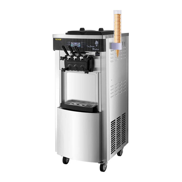
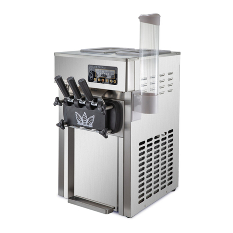
VEVOR SS240 User manual

¨
¨
¨
¨
Welcome to your machine:
Welcome to your VEVOR Model SS240 ice cream machine.Be cautious and follow instructions
carefully when operating, cleaning, and servicing the machine.
Twin twist flavor floor standing soft ice cream machine
Approved for dairy ,ice cream ,frozen yogurt and so on
Hopper refrigeration to maintain product temperature below40 (4℃)°F
Digital viscosity-control system to adjust and maintain product consistency
Ice Cream Machine
Operation Manual

SPECIFICATIONS MODELSS240
FLOOR MODEL GRAVITY FEED
Air Cooled Units
Air cooled units require a minimum of 6’‘ (200 mm) of clearance on all sides of the
freezer. Failure to allow for adequate clearance can reduce the refrigeration capacity of the
Electrical Hook-Up Installation for 220V-240V, 60 Hertz, 1 Phase
Check the data label in the rear panel for electrical specifications. The power supply must
be connected through the circuit breaker. This equipment is supplied with a 3-wire cord
.The cord provided for is 16 amp, therefore the wall outlet must over 16 Amp.
Equipment Parameters
Freezing Cylinder
Two,2 x 1.6 Liters
Mix Hopper
Two,2 x 12.5Liters
DIMENSIONS:
NET: 554x654x1340mm (WxDxH)
Packing: 650x800x1665mm (WxDxH)
WEIGHT
Net: 190kg Packing: 210kg
ELECTRICAL
Voltage AC: 1 Phase ,220-240V 60 Hz
Total Run Amps: 16 Amps
Power:2500W
rive Motor: One, 2.0HP
Refrigeration System
Main Compressor: One,5039BTU/hr R404a
Pre-cooling Compressor: 400 BTU/hr R134a
(BTU may vary depending on compressor
used.)
AIR COOLING
Air-cooled required minimum 152mm air
clearance around the freezer.
CAUTION:
THIS EQUIPMENT MUST BE PROPERLY GROUNDED! FAILURE TO DO
SO CAN RESULT IN SEVERE PERSONAL INJURY FROM ELECTRICAL SHOCK!
1
375
554
1340
538
642
965
805
654

Failure to install the machine within recommended limits will result in poor
performance of this system
CAUTION: After receiving the machine from logistics company, the machine need to be
placed steady for 6 hours to make sure the compressors work normally.
1.Uncrate the machine.
2.Remove 4 nuts holding the machine to the pedestal (Figure 1-1).
3.Raise the machine, then draw out the pallet (Figure 1-2).
Figure 1-1 Figure 1-2
Check the machine’s back panel of the nameplate .Make sure the working power fit
the machine. The unit must be connected to a properly grounded receptacle.
This machine is air cooling unit ,which require a minimum of 200mm of clearance
around both sides.
Keeping the working place dry and clean .Pay attention the insect and mice ,don’t
let them go inside of machine to destroy the wires and other parts.
After the installation press the wheel brake to make sure the machine in the fixed
position
Open the back panels(Figure 1-3) .Make sure all the components are not loose
during transport .Such as motor ,motor belt , compressor and so on
(NOTE: The maximum gradient that is allowed is 15 degree during movement )
D.
E .
F .
G.
H.
Figure 1-3
The machine you have purchased has been carefully engineered and manufactured to give
you dependable operation.
The VEVOR Model SS240 is highly sophisticated pieces of equipment, when properly
operated and cared for, will produce a consistent quality product. Like all mechanical
products, they will require cleaning and maintenance. A minimum amount of care and
attention is necessary if operating procedures outlined in this manual are followed
closely.
This Operator’s Manual should be read before operating or performing any maintenance
on your equipment.
2

The Model SS240 will NOT eventually compensate and correct for any errors
during the set-up or filling operations. Thus, the initial assembly and priming
procedures are of extreme importance. It is strongly recommended that
personnel responsible for the equipment’s operation, both assembly and
disassembly, go through these procedures together in order to be properly
trained and to make sure that no misunderstandings exist.
In the event you should require technical assistance, please contact your local
authorized Distributor.
MIX INFORMATION
The Hygeian ice cream mix is required to be used for frozen production. Mix can
vary
considerably from one manufacturer to another. Differences in the type of
ingredients,
quality, and quantity all have a different bearing on the finished frozen product. A
change
in machine performance that cannot be explained by a technical problem may be
related
to mix. Mix does not improve with age. Old mix or mix that has been stored at too
high
temperature can result in a finished product that is less than satisfactory from the
appearance and taste standpoint.
We are concerned about the safety of the operator when he or she comes in
contact with the freezer and its parts. We have gone to extreme efforts to design
and manufacture built-in safety features to protect both you and service
technician.
IMPORTANT- Failure to adhere to the following safety precautions may
result in severe personal injury. Failure to comply with these warnings may
damage the accessories and raise your operation cost.
1. DO NOT operate the freezer without reading this operator’s manual. Failure
to follow this instruction may result in equipment damage, poor freezer
performance, health hazards, or personal injury.
2. DO NOT operate the freezer unless it is properly grounded. Failure to follow
this instruction may result in electrocution.
3. DO NOT allow untrained personnel to operate this machine. Failure to follow
this instruction may result in severe personal injury to fingers or hands from
hazardous moving parts.
4. DO NOT attempt any repairs unless the main power supply to the freezer has
been cut off. Failure to follow this instruction may result in electrocution. Contact
your local authorized Distributor for service.
5. DO NOT operate the freezer unless all service panels and access doors are
restrained with screws. Failure to follow this instruction may result in severe
personal injury from hazardous moving parts.
6. DO NOT obstruct air intake and discharge openings: minimum of 200mm of
clearance around both sides.
7. DO NOT remove the door, beater and blades, or drive shaft unless all control
switches are in the OFF position. 3
Failure to follow this instruction may cause poor freezer performance and damage to the
machine.
The machine is designed to operate in normal ambient temperatures of 60°F to 75°F
Operating in higher ambient temperatures will result in degraded performance.
Safety Switch Display
screen
Control
button
Display
screen
Control Button
Refrigeration Wash Pre-cooling Standby
Up Down Shift Function/OFF
FUNCTION/OFF BUTTON
Press FUNCTION/OFF button to exit present mode, LCD display indicates All
function buttons are available. To change to other function, IT IS ALWAYS
NECESSARY to first Press FUNCTION/OFF button to return STOP.
REFRIGERATION BUTTON
Press button ,the main compressor will start to refrigeration .
When the number show 100% on the display screen,the refrigeration cycle will OFF
automatically. Display screen show ICE CREAM READY
SOFT
4

Refrigeration
state
Hardness level
Cooling progress
Hopper temperature and voltage
Cylinder temperature and Motor current
Motor speed and counter
The refrigeration state will blink on the screen during REFRIEGRATION is ON.
Press Can exit from Refrigeration state.
WASH BUTTON
Press WASH button, the machine will be in washing state. Only the beater
motor operate.
Press Can exit from WASH state .
PRE-COOLING BUTTON
This maintains product temperatures below 40°F in the hopper,keep mix fresh in hopper.
Press button , LCD display show Pre-cooling is ON .
Press button again can stop pre-cooling ,and LCD display show pre-cooling OFF.
STANDBY
This maintains product temperatures below 40°F in both the hopper and cylinder for long
time .At night ,can open standby to keep mix fresh .
Press button , LCD display show STANDBY is ON and start cooling ,
when cooling finish display show KEEPING FRESH
Press button can stop STANDBY ,and LCD display show STANDBY OFF
5

UP and DOWN BUTTON
UP and DOWN button use for increases and decreases the value
SHIFT BUTTON
SHIFT KEY use for move the cursor for setting
PARAMETER SETTING
Press and hold FUNCTION/OFF button for
5 seconds , machine will go to SETTING MENU
for parameter setting( Picture 4-1)
Picture 4-1
Press Shift button can select menu .Press button can confirm the setting
UP and DOWN button use for increases and decreases the value
Picture 4-2 Picture 4-3
General parameter setting(Picture 4-2)
a. Pre-cooling temperature . Can adjust the hopper temperature , factory default 5 ℃
b. Refrigeration cycle time : Can adjust cooling cycle time , factory default 5 minutes
UP and DOWN button use for increases and decreases the value
Counter reset (Picture 4-3) Select “yes”can Reset the counter to 0
Picture 4-4 Picture 4-5
6

Alarm Records (Picture 4-4)
Can record the alarms list for the machine
Buzzer function enable (Picture 4-5)
Select “YES” can cancel the buzzer
Restore Factory defaults (Picture 4-6)
Select “YES” can restore factory setting
ICE CREAM Hardness setting
Ice cream hardness from 1 to 20 , number 1 is
hardest and number 20 is softest .
Press and hold UP button for 3 seconds
,then hardness level at top right corner can be
adjust .
Press UP or DOWN button
can increases or decreases the hardness
Picture 4-6
Mix-low alert system
The mix-low sensor(Figure 4-8) , when mix low ,the display screen show LOW MIX ,and
buzzer will also start working to alert operator fill enough mix into the hopper.
CAUTION:: Machine will turn OFF COOLING automatically if low mix working over 15
minutes .Machine will restart cooling once filling enough mix .
Mix-low sensor
Figure 4-8
Figure 4-7
Safety Switch
When meet something urgently ,press Safety Switch(Figure 4-7) can cut off the power
supply for control systems .Machine will be stop working at once .
7

Dispensing door( 1) Draw valve(1) Retention pin(1 ) Handle(3)
Door gasket( 1) Design cap(3 ) Dispensing door
screw(4 ) Beater(2)
Beater gasket( 1) Internal drip tray( 2) Hopper cover(2) Drip tray(1 )
Feeding tube( 1) Lubricant(1) Tools(1 ) Wearing parts(1)
8
CAUTION:Please keep the accessories properly to avoid losing the
then machine can't running correctly .
accessories and
Equipment components

CAUTION:
When installing machine, please make sure that the machine is powered off and
step on the caster brake to prevent sliding.
9
Equipment component installation
g.Install the door screw to the dispensing door .
Be sure is tighten
e.Install the handle to the draw valve .
Note: Make sure the handle seat insert to the draw
valve stainless steel rail.
f. Check the dispensing door gasket installation .
This gasket need change every 1-3 months
according to the use.
d.Insert draw valves into dispensing door and
slots face outward, O-rings-first .Noted that the
middle draw valve different to the side draw
valve .Check the o- rings carefully before
installing the draw valve and change the o-
rings every 1-3 months according to the use.
c.Lubricate the o-rings on the draw valve
(Note: Draw valve o-rings should be lubricated
every time after cleaning the machine )
a.Unscrew the retention pin screw
ab
b.Pull out the retention pin
d
d
e
f
h.Install front drip tray to the drip tray screw .
The tightness of the drip tray screw can be
adjusted
hh
c
g
I
i.Check the internal drip tray on the side is
installed or not .(Note:If there have mix
leaking from the internal drip tray on the side
,means the beater rubber broken ,need change a
new beater rubber )

CAUTION:
Before powering on the machine, please reconfirm whether it meets the equipment
wiring standards. If it does not meet the machine standards, it may cause electric shock or
damage the machine! ! !
Before powering on the machine, check whether all the components are installed in place again! !
1.Turn on machine power button
2.Thoroughly mix and prepare at least 1.3 gallons of
product for each hopper, mixshould be cool and smooth
(free of large chunks)
3.Press WASH button
4.Once no air bubble coming out of the feeding hole in
hopper,then can install the feeding tube (inlet hole on side of air
tube at bottom)
5.Pull down the handle ,draw out 200ml product and let machine
running in WASH mode for 2 minutes
6.Press Function/OFF button after WASH running 2 minutes
7.Press Pre-cooling button ,turn on pre-cooling
8.Press Refrigeration button ,turn on refrigeration
9.A percentage display appears on the right side of
the screen, machine start cooling
10.Display screen display 100% means ice cream is
ready for serve .First cooling time around 10 minutes .
11.Pull the handle can make ice cream
12.The machine enters automatic refrigeration cycle state,
filling raw materials in time if lack raw materials
1
2
3
5
6
7810 11
CAUTION:
.
.
.
The ice cream producon me is based on the environment temperature, different raw materials
cooling me also different .
10
Frozen product operation
This machine is air cooling unit ,which require a minimum of 200mm of clearance around
both sides. During equipment is working don’t block the panel
Pay aenon to mix-low alarm ,add enough mix when mix-low alarm works
9

1.机器工作结束,关闭制冷功能
2.Press WASH button ,let machine wash for 5 minutes to soften product .
3.Remove the feeding tube inside hopper
4.Pull handle ,draw out all the product
5.Prepare water and pour it into the hopper
( warm water and no more than 122 more better )°F
6.Press handle and draw out water .Pour clean water into
hopper again and draw out ,do like this 2-3 times .
8.Unscrew the dispensing door screws
9.Remove the dispensing door
10.Remove the beater
11.Remove with beater rubber
12.Disassemble the dispensing door (refer to a-g at page 9)
13.Cleaning all parts after disassembling.
14.After cleaning, put the accessories in a dry place (do not soak in water)
NOTES: To expedite draining, turn off machine 30 minutes prior to soften product.
1.Press Function/OFF button ,turn off all function
7.Press Function/OFF button turn off the machine
2
4
3
1
56 6
7
8910 11
11
CLEANING
15. Please keep the beater dry and don't install on the machine immediately
after washing .Install the beater when start use the machine .

068 183 184 185 186
071
067
061 178 179 180 181 065 182
Item Part Description Item Part Description
1
2
3
4
5
6
7
067
068
183
185
184
071
186
061
12
13
14
15
16
17
18
178
179
180
181
065
182
CAUTION:
Please keep the beater ,dispensing door in a dry place , Do not soak in
water for long time . If the machine is stored for a long time, place the
dispensing door and beater separately ,don't install them on the machine
Door screw
Retention pin screw
Retention pin
Beater
Dispensing door
Design cap
Beater gasket
Handle
Handle seat
Draw valve-Side
Draw valve-Mid
O-O-O ring
O-ring
Door gasket
12
Specs—Dispensing door and beater

128
091
092
094
028
093
029
031
134
096
098
037
129
100 038 130
102 103
108107 109
112
114
113
115
116
119
118
105
120
033
131
132
133
Item Part Description Item Part Description Item Part Description
1
2
3
4
5
6
7
8
9
128
091
092
094
028
093
029
031
134
096
10
11
12
13
14
15
16
17
18
131
098
037
129
100
038
130
120
115
116
119
118
033
19
20
21
22
23
24
25
26
27
108
107
109
114
133
102
103 105
132
23
24
25
26
27
Condenser-main
Fan
Fan cover
switch baseplate
Arm - Return
Spigot Switch Cover
Power Switch
Assembly cylinder
Fan Capacitor
Thermostat
Dry filter
Drip pan
Expansion valve
Universal caster
Compressor- main
Precooling compressor
Rigid caster
Accessories – Compressor
Fan-precooling
Display board
o-ring
Motor
Start Capacitor – Motor
Side Drip Tray
Spring - Motor
Condenser-precooling
Run Capacitor – Motor
Belt-Motor
B u s h i n g - R e d u c e r P u l l e y
Pulley – Gear Box
Reducer
Microswitch
13
Specs—Internal Parts

Problem 1 : Product is too so /hard
Probable Cause
1. The hardness value is set incorrectly
2. Low mix in hopper
3. Improper mixing of product
4. Machine doesn’t have adequate venlaon
5. Machine isn’t cleaned/lubricated adequately
Remedy
1. Adjust the hardness value
2. Ensure hopper is at least half full
3. Follow manufacturer instrucons for mixing
product; ensure correct mix raos
4. Ensure at least 6-in. clearance on all sides
5. Clean and properly lubricate machine daily
Problem 2 : Cylinder temperature too low /Motor Overload
Probable Cause
1.Low mix in hopper
2. Improper mixing of product
3. Air tube isn’t installed correctly
4. Hardness adjustment is set incorrectly
5. Product is being drawn too quickly
Remedy
1. Ensure hopper is at least half full
2. Follow manufacturer instrucons for mixing
product; ensure correct mix raos
3. Clean air tube, ensure proper orientaon
4. Adjust hardness seng more so
5. Ensure air tube isn’t clogged, allow machine
2 to 3 seconds between servings
Problem 3 : High voltage / Low voltage
Probable Cause
Voltage too high :Voltage over 242V
Voltage too low: Voltage lower than 198V
Remedy
1.The electricity wire should bigger than 4 square
millimeter.
2. Should use independent electricity wire
3. Recommend use 5kva voltage regulator
Problem 4 : Product leaks into internal drip tray
Probable Cause
1. Improper or inadequate lubricaon of
beater gasket
2. Damaged, missing, or improperly installed
beater gasket
Remedy
1. Lubricant beater gasket during assembly
2. Replace beater gasket every 1–3 months
Problem 5: Hopper isn't cold enough
Probable Cause
1. Warm product was recently added
2. Hopper temperature setting is too high
3. Pre-cooling compressor or pre-cooling fan not works
Remedy
1. Allow at least 1 hour after adding new mix for hopper
temperatures to stabilize
2. Adjust hopper temperature more colder
3. Call Technical Support
Problem 6: Hopper is freezing
Probable Cause
1. low mix in hopper
2. Hopper temperature setting is too low
Remedy
1. Ensure hopper is at least half full
2. Adjust hopper temperature warmer
Problem 7 : Machine is making noise
Probable Cause
1. Improper assembly
2. Wearable parts need replacement
3. Internal cleaning/maintenance required
Remedy
1. Stop machine use, drain product with machine powered OFF; clean and inspect parts.
2. Replace wearable parts (including scraper blades) at least once every 3 months
3. Inspect parts carefully for damage, ensure proper assembly; replace as required
14
Troubleshooting

M11--Main motor M5--Pre-cooling Fan
M12--Main compressor S11--Microswitch
M3--Condenser Fan E1--Emergency switch
M4--Pre-cooling compressor
High pressure switch
Speed sensor
Microswitch
Display board data ca-
ble
+12V
COM1 Y8
COM2 Y9
DL2DL1LY7Y6
Y5Y4Y3Y2Y1
N
Transformer
Hopper temperature
Cylinder temperature
Mix low sensor
+
-
S11
E1
M4
M5
M3 M12 220V power supply
M11 D11 24V
RS T
UVWPRB
TA TC TB D12 D13 D14 D15 PLC COM COM10V A11 A12 A01 MOM M01GND
Inverter
ss240
14

The manual is intended to guide users in installation, operation, cleaning and online maintenance
procedures. The information contained in this manual may be changed due to the product improvements
without notice. Please contact us online or contact VEVOR technical support for information about machine
updates and training!
Table of contents
Other VEVOR Ice Cream Maker manuals