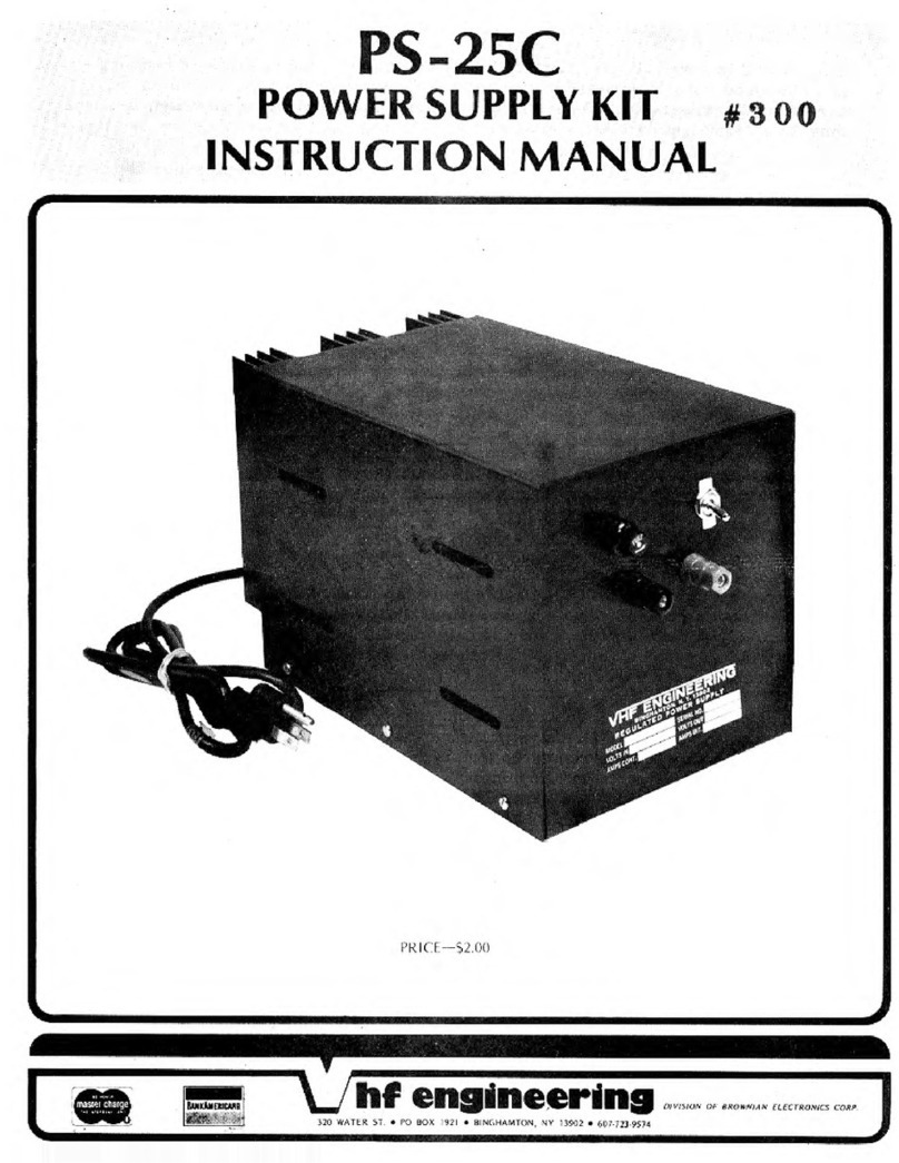
VHF Engineering PS-15C User manual

170
WATkR
ZT
PO
ROX
1971
.
RINGHAMTON
NY
11902
607-721-9574

The PS-15C
is
a well filtered regulated 12-14 volt power supply capable of handlin
up to 15 amps.
It
is
designed for con~municationsequipment where maximum
current
is
drawn less than 50 pcrcent of the time. For continuous operation,
it must be derated
approximately
20 percent.
*%@W$
PS-15C SPECIFICATIONS
@#
VOLTAGE OUTPUT: adjustable between 12 and 14 volts.
LOAD REGULATION:
2
percent fromno load to 15 anips.
CURRENT OUTPU'I 15 amps intermittent (50 percent duty cycle)
10 amps continuous.
CURRENT LIMITING: maximum short circuit current
1
amp nominal.
RIPPLE
:
50 MV at 10 amps.
AMBIENT TEMP:
OC
maximum.
LIMITED WARRANTY
Factory wired units are warranted for one year. The unit must be re-
turned to the factory postpaid with a note describing difficulty
and
date of purchase,
include a check to cover return postage. Our liability under warranty
is
limited
to repair, adjustment or replacement of units proven to be defective. No further
warranty
is
expressed or implied. Units modified or obviously misused will
not be covered by the warranty.
The parts in kits built according to our instructions carry the original
manufacturers1warranty. Defective parts must
be
returned for credit. Units
built from kits may be returned to the factory for repair and alignment for a
nominal charge, plus parts and shipping.
WARNING!
The input power connection
is
at
the ac line potential (115 or
230V
ac). Use caution when working
in this area.

PARTS LIST
-
PS3A
(Kit 7010190)
(Wired 7010191)
25000
MFD
40V (2010610)
.OO1
(2010370)
470MFD 16V (2010570)
.001 (2010370)
.01 (2010410)
1K 5% (2020240)
2K Pot (2020510)
1OK 570 (2020340)
5.6K 1/2W (2020300)
330 ohm 570 (2020175)
390 ohm 5% (PS15) (2020180)
3.3K 570 (2020270)
.1
ohm 5W (2020010)
Heat Sink Grease Capsule
(
3050200)"
P.C. Board (4040220-1)
Heat Sink
Small on PS3A
&
PS15 (4020100)
Large on PS25 (4020150)
3 Keystone Pins (4060130)
Hardware
Instruction Sheet (5010203)
*C1
is
not supplied with PS3A kit.
When using PS3A with external pass
transistors R7
is
changed to 100 ohm
1
W resistor (2020110)

.
CIRCUIT
l,3t'SCNIF"I
ION
The PS-3A regulator card can supply up to
6
amps of regulated 12-14 volts from
an unregulated source. It
is
designed for communicptions equipment where maximum
current
is
drawn less than 50 percent of the time. For continuous operation, it must be
derated to 3 amps with the heat sink supplied. The maximum current
is
limited by the
power dissipation (input voltage minus output times current) and the current capabilities
of the pass transistor, which
is
90 watts and 10 amps respectively at room temperature
for the TIP3055. With a supply voltage of 20 volts, the PS3A
will
handle 6 amps by
adding additional heat sinking to keep the case temperature of the TIP3055 below 120°
centigrade. With the addition of external pas€ transistors, currents up to amps can be
k
regulated.
When using the PS3A without external pass transistors, the maximum short
circuit current
is
6
amps. When used with external pass transistors,
R-7
is
changed
to100 ohms. The maximum 'current of 6 amps
is
multiplied
by
the number of pass
transistors. The unregulated input must be at least two volts above the output under
load to keep the pass transistors out of saturation. Any ripple on the input voltage
must be added to the 2 volts difference. When the pass transistor saturates regulation
is
lost.
THEORY
OF
OPER.4TJON
The IVE550
is
a precision voltage regulator chip that contains a zener voltage
reference, operational amplifier, current limiter, and pass transistor. -4 portion of the
output voltage controlled by R-4
is
compared to a reference voltage, any difference or
error
is
amplified by the op-amp and changes the bias on the internal pass transistor to
eliminate the error. The reference voltage for the NE550
is
1.6 volts. Therefore, the
t
autput voltage is the ratio of the voltage divider (consisting of R-1, 2, and 3) times
1.
6.
The current limiter transistor saturates when a voltage of .6
is
applied between pins 2 and
3, shuting down the output. Therefore, with a
.1
ohm resistor for R-5, the supply will
;hut $own
when.
a-~urrent
Qf
6
amps
is
reached.
The current limiting section of IC1 operates when
a
vol
between pins
2
and 3 of IC1. This voltage
is
the algebraic sum of
developed across R-5 and
R-7.
Reverse voltage
is
the result of
r
through R-5 and R-6 to ground. Its value
is
dependent mainly
and
the value of
R-6.
Forward voltage (disabling voltage)
is
applied across
R-7
by the
load current through the paralled
E-B
junctions of the pass transistors and
.1
ohm
emitter resistors. Its value
is
a function of load current. When the voltage across
R-7
s
.6
volts higher than the voltage across R-5, current limiting results.
3UPPLIES USING OVP
The over-voltage protection
(OliP)
is essentially a crowbar circuit which prevents
the output voltage from rjsing above 14 volts.
if
t!le
supply voltage (pot on PS3A board)
is
set too high, the OVP will shut down the supply as soon as it
is
turned on. To reset
the OVP: turn the power off
-
wait about one minute for the filter capacitor to discharge
-
turn the regulator pot down
-
reapply power
-
adjust the regulator pot for the desired output
voltage.
Install IC first. The
T1P
3055 transis!or
is
installed with the metal side down.
The
6-32
screw holds the heat sink on top
of
the transistor. Be sure to use some silicon
grease \)ctween
the
)]catsink and
the
trar~slfor.
The mctal part of
the
transistor
is
interndly connected to
t11e
collector. Therefore, the screw and heat sink have full
voltage on them. Care should be taken to prevent them from grounding out. Observe
pclarity on the electrolytic condensers. The board
is
usually mounted by the filter con
dcnser. If it'is used without the filter condenser (when used with an existing filtered
unregulated supply) it may be ]mounted on stand offs by drilling mounting holes
in
the
corners of the board,

PS15C INSTRUC'TIONS
Assemble the PS-3A regulator board as follows (referto the pictorial of the
parts layout).
a.
)
Install the IC first, making sure the notch or dot
is
near
pin
1
as marked on the board. b.) Bend the leads on Q1 towards the metal
side at a 90 degree angle. c.
)
Coat the metal side of Q1 with the white heat
sink grease and place it in the center of the
"U"
shaped heat sink. d.) Mount
this assembly to the component side of the circuit board with 6/32 hardware.
e.
)
Mount the remaining components as shown. NOTE: Be sure to substitute
the 100 ohrn
1
watt resistor in the PS15C kit for the
.1
ohm
5
watt supplied
with the PS-3A.
Remove the power transformer from the chassis and set it aside temporarily.
Mount the large filte~condensor with its bracket and four 6/32
X
$I'
screws
and nuts. The brac~etmust be preformed by placing the condensor on a flat
surface
ar.d
bending the bracket around it. Make sure the positive connection
of the condensor
is
towards the rear of the chassis before tightening the
bracket
.
3.) Mount the binding post, on-off switch and fuse holder as shown in the parts
layout. Mount the four rubber feet on the bottom corners of the chassis.
4.
)
Insert a rubber grommet in the 318" hole on the rear apron. Insert the power
cord through the grommet and strip outside jacket 12" from the end. Place
the power transformer into the chassis with the primary on the right side
(looking from the front panel). Mount-the power transformer with
four
10132
X
screws, washers, and nuts. Be sure to place
a
nylon cable clamp
on the right rear corner of the power transformer as shown.
Slip the end of the power cord through the nylon cable clamp. The insulation
should be flush with the inside edge of the clamp. Tighten the 8/32 nut to
secure the power cord. Locate the green (ground)lead from the power cord
and measure 4" from the cable clamp and cut. Strip and solder to ground
lug located at the base primary side of the transformer.
TRANSFORMER PRIMARY WINDING
5.)
a.
)
For llOV operation:
Cut and strip two 2" pieces
#I8
brown wire. Connect one wire from the
primary terminal
#1
to terminal
#3.
Connect the other wire from
terminal #4 to terminal #2. Solder pins 2 and 3 only.

h.
)
For 220V operation:
Cut and strip one
1"
piece of #18 brown wire. Connect one end to
primary terminal
#2
and the other end to terminal #3 power transformer
Solder both connections.
Locate the white wire coming from the power cord and measure
3"
from
the cable clamp. Strip and solder to the primary terminal marked
1
(on
the pictorial). Locate the black'wire coming from the power cable. Run
it along the right hand side of the chassis, then across the front panel
underneath the binding post and bring it
up
to the center terminal of the
fuse holder. Strip and solder to the center fuse holder. Cut 3+" length of
#18 brown wire and strip both ends
11
8". Solder one end
t3
the fuse holder
side terminal and the other end to the inner terminal of the on-off switch.
7.
)
Cut a 5%"length of #18 black wire and strip both ends
11
8". Solder one end
to the remaining lug on the switch and the other end to terminal #4 on the
power transformer.
REFER
TO
THE BRIDGE RECTIFIER DETAILED DRAWING DURING THE FOLLOWING
STEP
8.)
Prepare the following wires
:
a.) Cut a 10" black #14 wire and strip both ends
$I1.
b.) Cut a 5" black #14 wire and strip both ends
2".
c.
)
Cut a 9" red #14 wire and strip both ends
2".
d.) Cut a
6"
red #18 wire. Remove
$-I'
of insulation from the center of
the wire and strip both ends
2".
9-1
Solder the prepared wires into the bridge as follows:
a.) Solder one end of the 10" #14 black wire to the minus terminal.
b.) Connect one end of the red #14 wire to the positive terminal. Wrap
the center of the red #18 wire around the terminal and solder.
c.
)
Crimp and solder a terminal lug to the red lead.
d.
)
Crimp and solder a terminal lug to the end of both black leads.
10.) Mount the two pass transistors on the heat sink as follows:
a.
)
Coat both sides of
a
mica insulator with heat sink grease. Slip the
coated insulator over the pins of the transistor. Carefully plug the
transistors through the heat sink into a socket held on theinside. Be
sure to orient the transistor sothe pins are centered in the holes of
the
heat sink and the positioning holes of the sockets line up properly
Secure the entire assembly using
#6
X
518" self tapping screws.
IF
THE PINS OF THE TRANSISTOR ARE INADVERTANTLY SHORTED TO THE HEAT
SINK, MAJOR DAMAGE TO THE SUPPLY CAN RESULT


heat sink.
standoff in the center hole closest to the edge of the heat sink
-40
X
318 screw and lock washer between the standoff and the
Coat the bottom of the previously prepared rectifier with heat sink grease
(place an 8-32
X
318" screw through the center hole in the rectifier and
mount it
in
the remaining hole between the transistors on the heat sink).
Secure with an 8-32
X
$"
hex nut placed between the center heat sink fins.
Before tightening, align the bridge sothat it is parallel with the heat sink
and the red #18 wires are facing thelupperleft hand side.
13.) Connect two
.1
ohm
5
watt resistors from the emitter connections of each
P
pass transistor to the standoff insulator. The emitter is the transistor
socket solder lug closest to the standoff. Put each lead through the hole
in the lug and crimp securely before soldering.
14.
)
Solder one
sf
the red #18 wires from the rectifier to each pass transistor
collector. The collector
is
the center connection on the socket.
15.) Strip about of insulation off a 8" #18 green wire about 3 118" from one end.
Strip 114" off each end. Wrap the
i"
bare section around the base lead lug
of the right pass transistor socket and solder. Connect the short end to the
other pass transistor base lead lug and solder.
Strip both ends of a 15"
#14
red wire back
3".
Strip both ends of a
6"
#18
red wire back 1/4". Connect one end of each wire to the standoff insulator
and solder.
-
-
--
Take the heat sink, lay it fin side down, being sure that the bridge rectifier
is
closest to the rear edge of the chassis. Solder one of the secondary leads
on tbe power transformer to one of the terminals marked "AC" on the
bridge rectifier. Now solder the other secondary lead to the remaining lug
marked "AC" on the bridge rectifier.
Mount the heat sink to the main chassis with two 8-32
X
4"
screws, washers
and nuts.
Mount the PS-3A board on the capacitor using #lo-32'hardware
in
the
following sequence: Screw
-
terminal lug
-
flat washer
-
PC
board
-
capacitol
The lug on the two #14 black wires to the negative terminal (toward the
front cover), and the lug on the #14 red wire to the positive terminal.
Tighten both screws securely.
ANY
RESISTANCE AT THESE POINTS
WILL
HAVE AN ADVERSE EFFECT
ON
REGULATION

20.
)
Connect the black #14 wire to the black terminal post. Connect the red #14
wire to the red terminal post. Connect a 220 ohm 2 watt resistor between the
terminal posts and solder.
21.) Solder the red #18 wire from the stand off insulator to the top (VS) terminal
on the PS-3A regulator card. Solder the green #18 wire to the bottom (VO)
terminal.
22-
1
Place the OVP on top of the capacitor bracket orienting it sothat the red
l$ad
is
opposite the red binding post and the black lead
is
opposite the
black binding post. Cut and strip leads, then solder the red lead to the
r
d binding post and the black lead to the black binding post. This completes
t
t
e wiring of the PS15C power supply.
BEFORE APPLYING POWER, CAREFULLY CHECK ALL SOLDER CONNECTIONS
B'INAL TEST AND ASSEMBLY
1.
)
Install the fuse in the fuse holder (5 amp for 100V, 3 amp for 220V).
2.) Set the voltage adjust control (R-2) in the regulator card to mid position.
3.
)
Connect a volt meter to the output terminals. Set the meteretoread
20-50 volts full scale.
4.) Pluginsupplyandturnswitchon.
AdjustR-2foranominal13.8volts
output
.
5.
)
If the control
is
adjusted above 15 volts, the
0.
V.
P.
will shut down the
supply. The
0.
V.
P.
is
reset by turning off the supply for approximately
one minute (be sure to reset control to mid position).
Slide the four Tinnerman fasteners over the mounting holes on the main
chassis flanges.
Place the cover on theassiswith the beveled end toward the front. Line
up the mounting holes with the Tinnerman fasteners and secure the cover
using four
#6
X
318 self taping screws.

TROUBLE
SHOOTING
NO
OUTPUT
1.
)
Check fuse or circuit breaker.
2.)
The overvoltage protection device may be shutting down the supply as
soon as it
is
turned on. To reset the OVP: Turn the power off
-
wait
about one minute for the filter capacitor to discharge
-
turn the reg-
ulator pot down
-
reapply power
-
adjust the regulator pot forthe desired
output voltage.
3.
)
Measure voltage across filter capacitor.
a.) If 22-25 VDC
is
present, proceed to step
7.
b.) If no voltage
is
present, proceed to step 4.
4.)
Check the bridge rectifier for shorts or open.
5.
)
Check the power cord continuity.
6.
)
Check the transformer primary and secondary for continuity.
7.)
Measure the voltage at the base of the pass transistor on the
PS3
card.
-
This measurement can be made at the "VO" terminal.
a.) If no voltage
is
present, proceed to step 10.
b.)
If 12-24 volts
is
present, proceea to step
8.-
-.
8.)
Check the pass transistor on the
PS3
card for open junctions.
9.
)
Check the
.1
ohm resistors for open circuit.
10.)
-
Measure the voltage at the base of
Ql.
a.) If the reading
is
12-24 volts,
Q1
may be defective. (see test chart
below) Check carefully for cold solder joints.
b.) If the reading
is
0
volts, proceed to step
11.
11.
)
Check the voltage at IC1 pin 4.
a.) If the reading
is
over
1.6
volts, check
FU,
R2, and
R3
for Qpen.
b.
)
If
the reading
is
below 1.6 volts, check the voltage on IC1 pins
11
and
12.
If it
is
between 22-24volts, IC1 may be bad. If it
is
0
volts, check for open land or cold solder joints on circuit board.

VOLTAGEDROPUNDERLOAD
1.)
Reduce the load and recheck the output voltage. The current limit will
reduce the output voltage
if
a load greater than the supply can handle
is
applied.
2.) Check the voltage across the.filter capacitor (Cl)under load.
a.
)
If the reading
is
under 20 volts, proceed to step 4.
b.
)
If the reading
is
20-24 volts, proceed to step 3.
3.) Check the solder connections to the front panel output terminals. Be
sure that the screws which hold the PS3 in place are tight.
4.
)
Check diode Dl for an open junction.
5.)j
Check the solder connections between the transformer and rectifier.
6.
)1
Be sure that the screws which hold the PS3 in place are tight.
7-
\
Check
Ql
for an open junction (see chart below).
If
Q1 checks good, ICl
may be bad.
EXCESSIVE
HUM
1.
)
_
Be sure that the screws which hold the
PS3
in place are tight.
2.
)
Check the bridge rectifier for open diodes.
3.
)
Check line voltage. Excessively low line voltage may cause hum
under heavy loads. Lowering the output voltage of the supply may
correct this problem.
Table of contents
Other VHF Engineering Power Supply manuals