1 Function
1.1 Input voltage range
¡The range is from 85 VAC to 264 VAC or 120 VDC to 350 VDC.
¡In cases that conform with safety standard, input voltage range is
AC100-AC240V(50/60Hz).
¡AC input voltage must have a range from 85 VAC to 264 VAC for
normal operation. If the wrong input is applied, the unit will not
operate properly and/or may be damaged.
1.2 Inrush current limiting
¡Inrush current limiting is built-in.
¡If a switch is being used for input, ensure that it is configured to
handle the input inrush current.
¡A thyristor is used for protection from inrush current. When turning
the power OFF and then ON again within a short period of time,
inrush current limiting may be disabled; therefore ensure enough
time before switching ON.
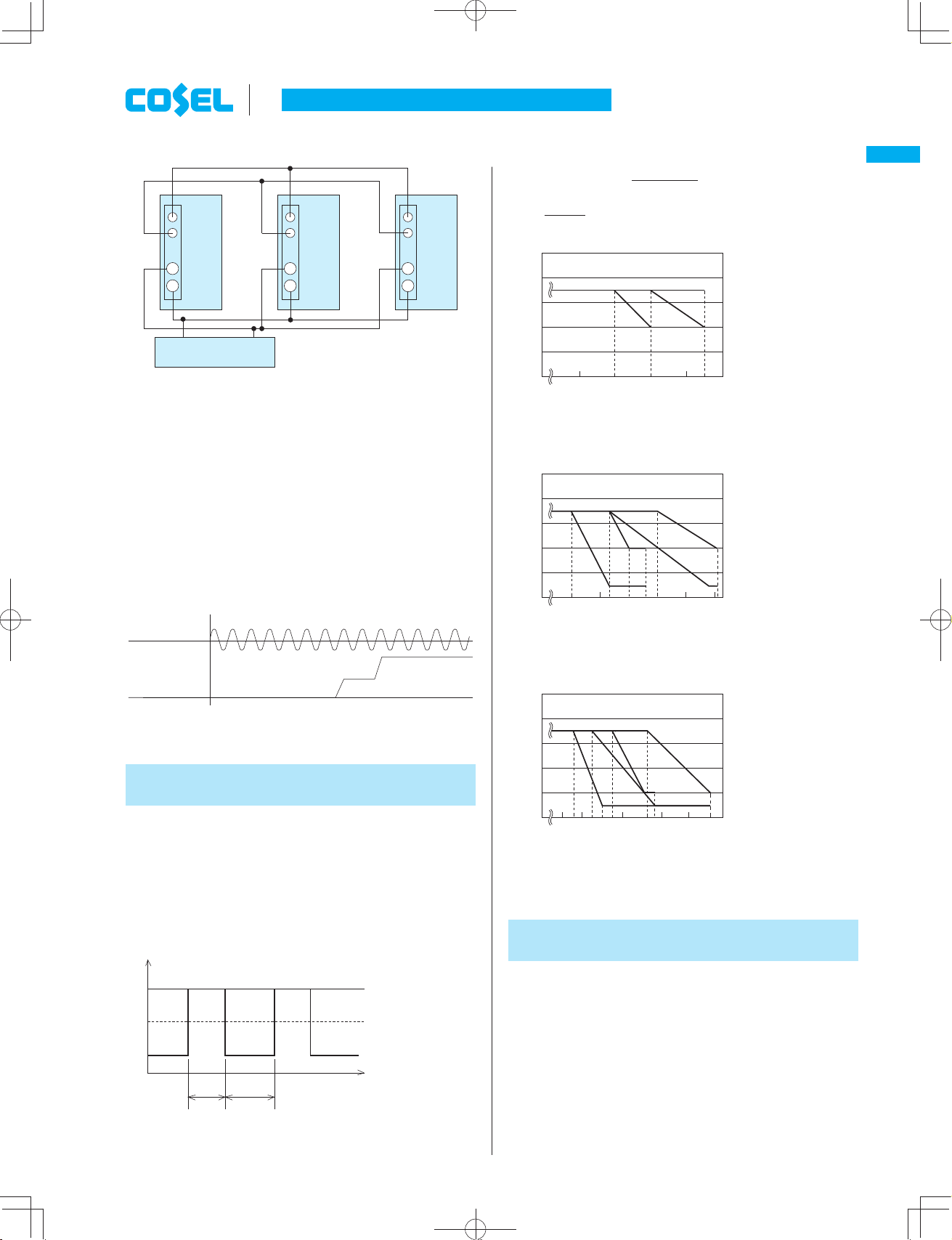
1.3 Overcurrent protection
¡Overcurrent protection is built-in and comes into effect at over
101% of the peak current in. Overcurrent protection prevents the
unit from short circuit and overcurrent condition.
The unit automatically recovers when the fault condition is cleared.
¿Intermittent current characteristics
¡When the output voltage drops more than 50% of the rated output
voltage value at overcurrent, the average output current is re-
duced by intermittent operation of power supply.
1.4 Peakcurrent protection
¡Peakcurrent protection is built-in (The protection circuit operates
when load current exceeds the rating current and the use deviates
from the condition in Instruction Manual 4).
If this function comes into effect, the output is shut down (delayed
shut down).
The minimum interval of AC recycling for recovery is 3 to 4 min-
utes (*).
*The recovery time varies depending on the voltage and load at
the time the protection activated.
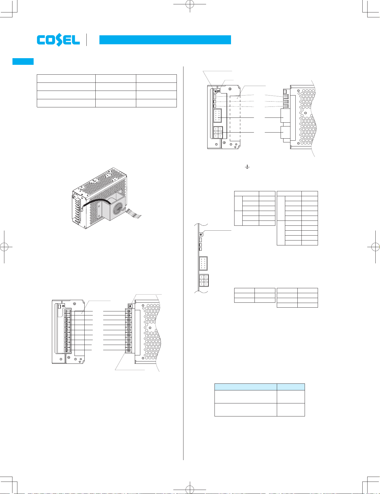
1.5 Thermal protection
¡Thermal protection circuit is built-in and shut down under following
condition.
1When the current and the temperature which exceed from the
derating curve.
2The case FAN stops or air flow is interrupted and the amount of
the wind decreases.
If the thermal protection activates, shut off input voltage, remove
the cause of the overheating, wait for the unit to cool down, and
recycle to recover output voltage.
1.6 Overvoltage protection
¡Overvoltage protection is built in. When the overvoltage protec-
tion activates, shut off input, wait for at least 3 to 4 minutes, and
recycle to recover output voltage(*).
*The recovery time varies depending on input voltage.
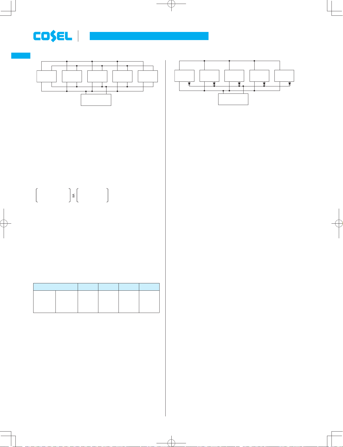
Remarks : Please avoid applying the over-rated voltage to the out-
put terminal. Power supply may operate incorrectly or fail. Incase
of operating a motor etc. , please install an external diode on the
output terminal to protect the unit.
1.7 Output voltage adjustment range
¡Adjustment of output voltage is possible by using potentiometer.
¡Output voltage is increased by turning potentiometer clockwise
and is decreased by turning potentiometer counterclockwise.
1.8 Isolation
¡For a receiving inspection, such as Hi-Pot test gradually increase
(decrease) the voltage for the start (shut down).
Avoid using Hi-Pot tester with the timer because it may generate
voltage a few times higher than the applied voltage, at ON/OFF of
a timer.
If the unit is tested on the isolation between input & output and
output & FG, remote ON/OFF (option) must be shorted to outputs.
2 Assembling and
Installation Method
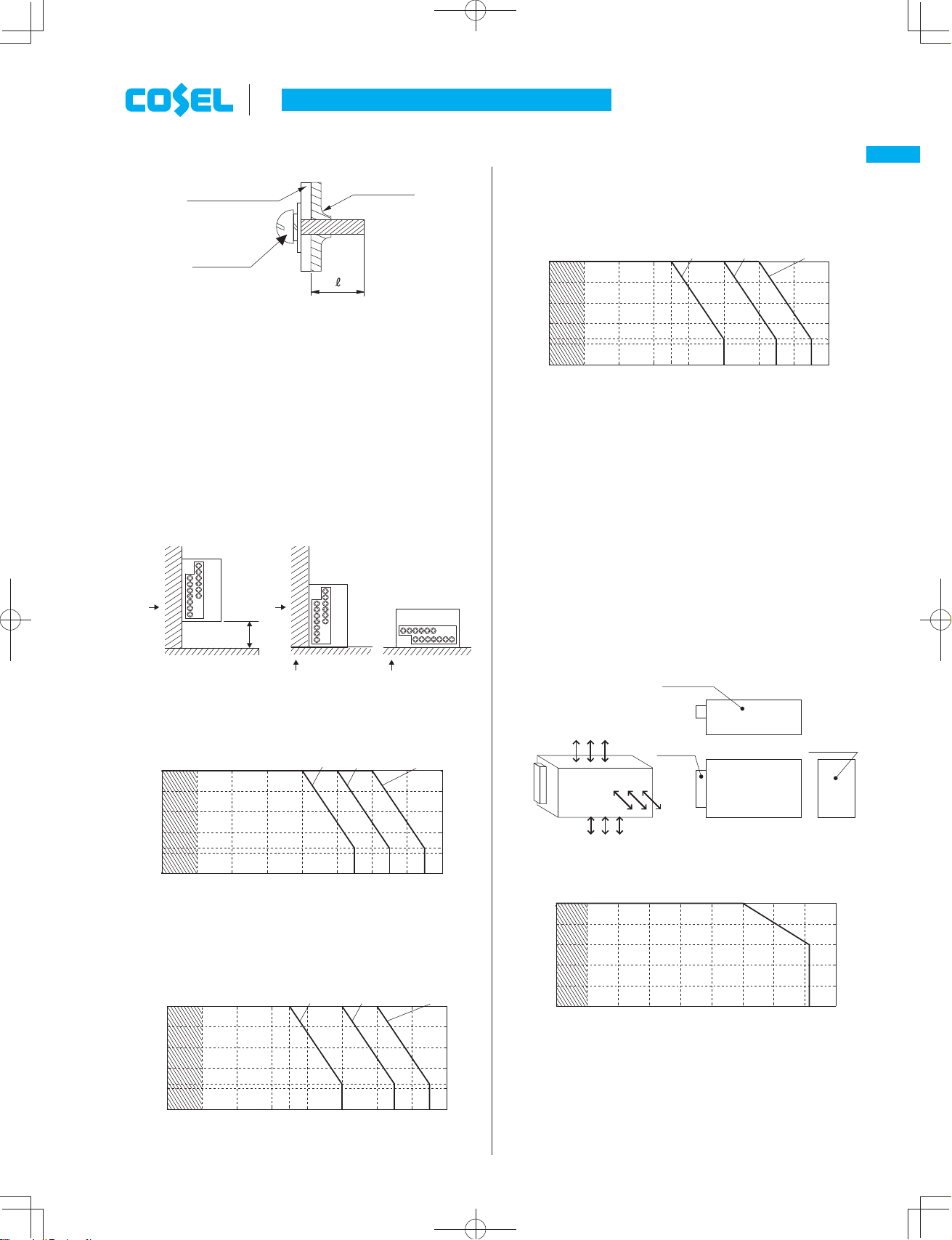
2.1 Installation method
¡When two or more power supplies are used side by side, position
them with proper intervals to allow enough air ventilation. Ambi-
ent temperature around each power supply should not exceed the
temperature range shown in derating curve.
¡Fix firmly, considering weight, though it can be used by the instal-
lation method shown in Fig.2.2.
2.2 Mounting screw
¡The screw should be inserted up to 6mm max from outside of the
power supply to keep a distance between inside parts and an iso-
lation (Fig.2.1).
AC-DC Power Supplies Enclosed Type Instruction Manual
ADA-10
ADA
meada1.inddADA-10me ada1 indd ADA-10 2015/08/079:23:572015/08/07 9:23:57
Artisan Technology Group - Quality Instrumentation ... Guaranteed | (888) 88-SOURCE | www.artisantg.com