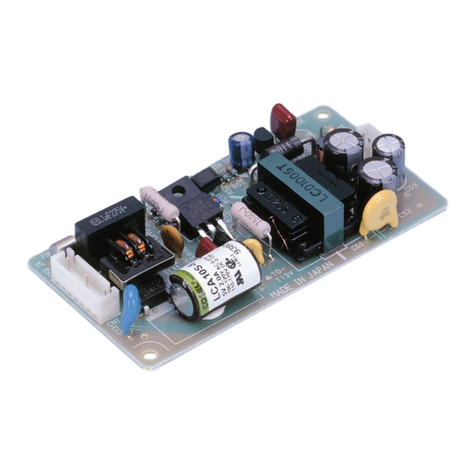
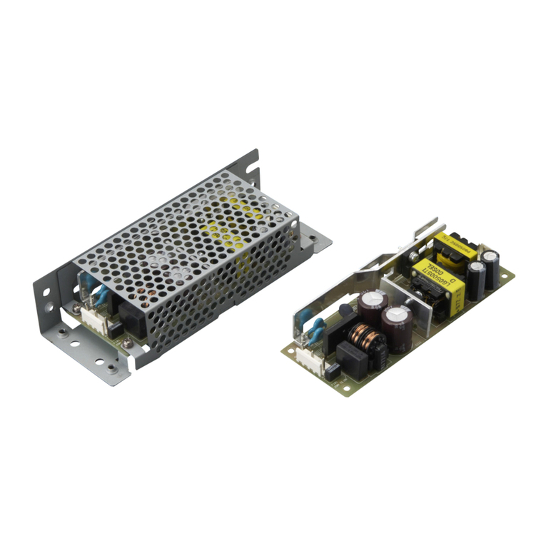
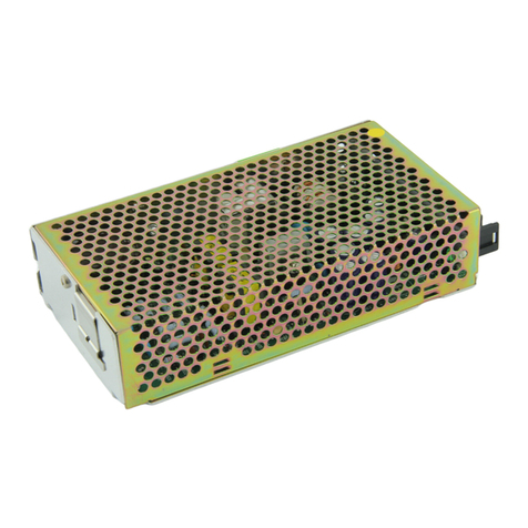
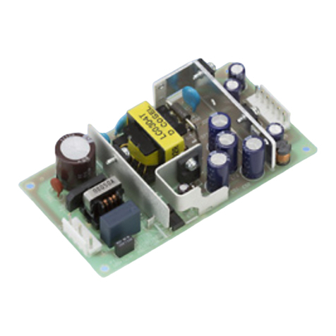
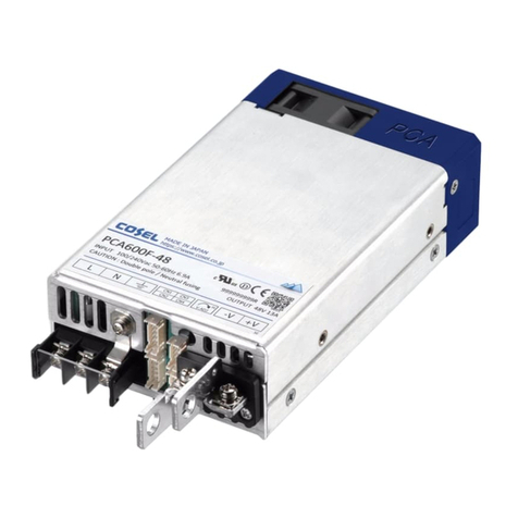
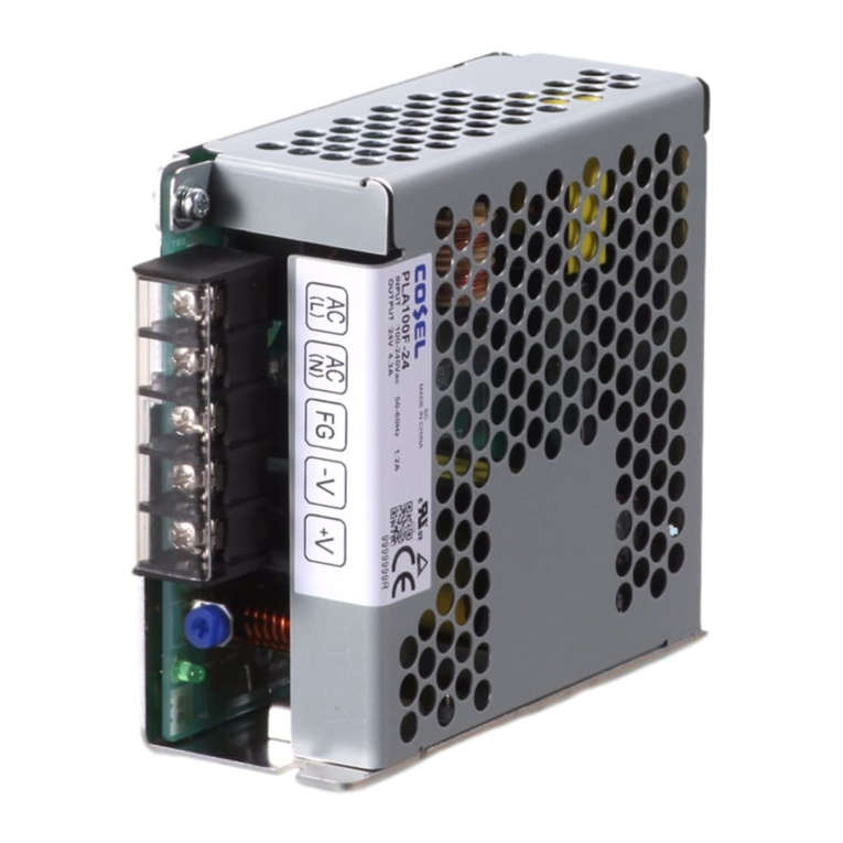
Cosel SNA-01 User manual

I-9
Noise
Filter
SNR series (10A)
Ripple noise attenuation type for switch mode power supplies(DC)
SNR -10 -223 -O
Ordering information
1 2 3 4
Features of SNR series (10A)
Circuit Diagram Derating Curve
Ripple noise attenuation type for switch mode power supplies(DC)
-50 VDC -Best filter for switch mode power supplies of
analog circuits
50 60 70 80-20 -10 0 40-40 -30 71
20
0
100
80
60
40
50
Ambient Temperature [C]
Load Factor [%]
1Model Name
2Rated Current
3Line to ground capacitor code:See table 1.1.
table1.1 Line to ground capacitor code
Code Line to ground capacitor (nominal value)
000 Not Provided
223 22000pF
4Options
D
:DIN rail installation type
T
:Terminal block type
DT :Terminal block and DIN rail type
¡Expected life : 10 years
Specifications
No. Items SNR-10-223
Interfare:Connector
1 Rated Voltage DC[V] 50
2 Rated Current DC[A] *110 (Peak 20)
3 Test Voltage (Terminal-Mounting Plate) 500 VAC (Cutoff Current = 100mA), 1minute at room temperature and humidity
4 Isolation Resistance (Terminal-Mounting Plate) 500 VDC 50MWminute at room temperature and humidity
5D.C Resistance[mW]20 max
6 Operating temperature -40 to +71C(Refer to Derating Curve)
7 Operating humidity 20 to 95%RH (Non condensing)
8 Storage temperature/humidity -40 to +75C/20 to 95%RH (Non condensing)
9 Vibration 10 to 55Hz, 19.6m/s2(2G), 3min. Period, 1hour each X, Y and Z axis
10 Impact 196.1m/s2(20G), 11ms Once each X, Y and Z axis
11 Safety agency approvals UL60950-1, C-UL (CSA60950-1), EN60950-1
12 Case size (without projection) /Mass 52X35X117 mm (WXHXD) /140g max (Option : -D, -T, -DT refer to external view)
*1Peak current for 10 sec. And Duty 35% max, refer to Instruction Manual 5. In detail.
: Mounting PlateCY : Line to ground capacitor Co : Electrolytic capacitor
CY
+Vin +Vout
-Vout
-Vin
Co
+
CY
*
The dimensions change when the option is set.
Refer to External view.
DIN rail installation type and Terminal block type are option
Terminal block type
DIN rail installation type
IN OUT
OG PQKUGHKNVGT0$KPFF +

I-10
Noise
Filter
SNR series (10A)
External view
35
-Vout
-Vin
+Vout
+Vin
TB1 TB2
106
117
40
52
117
106
52
40
1
6
1
6CN2
CN1
35
8-M3
7.6
6.2
Function
Pin No.
CN2
+Vout
-Vout
4,5,6
1,2,3
CN1
+Vin
-Vin
4,5,6
1,2,3
Function
Pin No.
(Mfr:J.S.T)
Terminal
Mating connector
I/O Connector
CN1,CN2
B6P-VH VHR-6N Bulk:BVH-21T-P1.1
Reel:SVH-21T-P1.1
¶Tolerance : ±1
¶Mass : 140g or less
¶PCB Material /thickness : CEM3 /1.6mm

Mounting plate : Iron (surface finishing : nickel plating) t=1.0
¶Case : PBT
¶Dimensions in mm

Keeping drawing current per pin below 5A (7A at peak current)
for CN1 to CN2
¶Tolerance : ±1
¶Mass : 150g or less
¶PCB Material /thickness : CEM3 /1.6mm
¶Mounting plate : Iron (surface finishing : nickel plating) t=1.0
¶Case : PBT
¶Dimensions in mm
¶Terminal block s
crew tightening torque M3:0.8N-m (8.5kgf-cm) max

Keeping drawing current per pin below 8A (10A at peak current) for TB1 to TB2
O
p
tion harness : Refer to Instruction Manual 4
Mounting
Plate
Mounting
Plate
Terminal cover
2-f4.5 2-f4.5
Name Plate Name Plate
Mounting Hole Mounting Hole
±0.5
±0.5
±0.5
±0.5
(9) 835
(9) 835
FG
M4
10
52
108.5
112
OUT
IN
IN
OUT
10
M4
FG
-Vout
-Vin
+Vout
+Vin
8-M3
108.5
112
52
CN1 CN2
1
6
1
6
TB1 TB2
7.6
6.2
DIN rail
Name Plate
Mounting Plate
Terminal cover
Name Plate
DIN rail
¶Tolerance : ±1
¶Mass : 150g or less
¶PCB Material /thickness : CEM3 / 1.6mm

Mounting plate : Iron (surface finishing : nickel plating) t=1.0
¶Case : PBT
¶Dimensions in mm

Keeping drawing current per pin below 5A (7A at peak current)
for CN1 to CN2
¶Tolerance : ±1
¶Mass : 160g or less
¶PCB Material /thickness : CEM3 /1.6mm

Mounting plate : Iron (surface finishing : nickel plating) t=1.0
¶Case : PBT
¶Dimensions in mm
¶Terminal block screw tightening torque M3:0.8N-m (8.5kgf-cm) max

Keeping drawing current per pin below 8A (10A at peak current) for TB1 to TB2
Option harness : Refer to Instruction Manual 4
Function
Pin No.
CN2
+Vout
-
V
out
4,5,6
1,2,3
CN1
+Vin
-Vin
4,5,6
1,2,3
Function
Pin No.
Terminal
Mating connector
I/O Connector
CN1,CN2
B6P-VH VHR-6N Bulk:BVH-21T-P1.1
Reel:SVH-21T-P1.1
(Mfr:J.S.T)
Standard Type
DIN rail installation Type
Terminal block Type
Terminal block type+DIN rail installation Type
¡Note when installing the noise
filter on a DIN rail.
When the noise filter is grounded through the
DIN rail, the proper noise attenuation may not be
achieved.
Be sure to connect the FG terminal of the noise
filter body to the earth.
CN1 CN2
OUT
IN
1
6
1
6
DIN rail
Name Plate
OG PQKUGHKNVGT0$KPFF +

I-22
Noise
Filter
Characteristic Data <Reference Data>
SNA/SNR series
¡Example of attenuation output noise.
(Room temp,Room Humi)
BW:500MHz
LCA10S-12
12V 0.9A
LCA10S-12
LCA30S-12
LCA50S-12
LCA10S-12+SNA-01-223
LCA30S-12+SNA-03-223
LCA50S-12+SNA-06-223
(Room temp,Room Humi)
BW:500MHz
LCA30S-12
12V 2.5A
(Room temp,Room Humi)
BW:500MHz
LCA50S-12
12V 4.3A
5mV/DIV
4 S/DIV
5mV/DIV
4 S/DIV
10mV/DIV
4 S/DIV
5mV/DIV
4 S/DIV
5mV/DIV
4 S/DIV
10mV/DIV
4 S/DIV
This product only reduces ripple noise of the switch mode
power supply. It cannot be used effectively to reduce ripple
noise at line frequency.
SNR-10-223
LEP240F-24 LEP240F-24+SNR-10-223
(Room temp,Room Humi)
BW:500MHz
LEP240F-24
24V 10A
50mV/DIV
4 S/DIV
50mV/DIV
4 S/DIV
Measured by differential probe (KEISOKU-GIKEN:DP-100).
SNA-03-223SNA-01-223
SNA-06-223
¡Attenuation Characteristic(Static characteristic) Differential Mode
Common Mode
Frequency[MHz]
Attenuation[dB]
120
100
80
60
40
20
0
0.01 0.1 1 10 100
¡Attenuation Characteristic(Static characteristic) Differential Mode
Common Mode
Frequency[MHz]
Attenuation[dB]
120
100
80
60
40
20
0
0.01 0.1 1 10 100
¡Attenuation Characteristic(Static characteristic) Differential Mode
Common Mode
Frequency[MHz]
Attenuation[dB]
120
100
80
60
40
20
0
0.01 0.1 1 10 100
¡Attenuation Characteristic(Static characteristic) Differential Mode
Common Mode
Frequency[MHz]
Attenuation[dB]
120
100
80
60
40
20
0
0.01 0.1 1 10 100
OG PQKUGHKNVGTKPFF +

I-23
Noise
Filter
¡ Power supply for an operational amplifier.
¡ Single output power supply.
Ripple noise attenuation type for switch mode power supplies(DC)
Instruction Manual
¡ This filter uses polarized components (electrolytic capacitor), The
filter will break if reverse voltage is applied to the input/output
terminals. Please exercise caution when wiring.
1
Wiring to Input/Output
terminals
2
Application examples
4
Optional Parts
¡ To apply for safety standard approval using this Noise Filter, the
following conditions must be met.
¿ The unit must be used as a component of an end-use equipment.
¿ The unit must be used in the secondary circuit that is insulated
from the primary circuit through double or reinforced insulation.
¿ The mounting plate (FG) must be connected to safety ground of
end-use equipment.
3
Safety Considerations
¡ The harness for Input/Output of noise filter is available.
Model Harness model
SNA-01 H-OU-8
SNA-03 H-OU-8
SNA-06 H-OU-9
SNR-10 H-OU-18
The same harness model applies to both input and output.
Sold in units of 1 piece.
5
Peak current (SNR)
¡ Peak current is possible to draw as below.
t1 [10 [sec], lave = Ip t1 + Io t2 [rated current
t1 + t2
t1
t1 + t2 [Duty
Duty is depended on peak current, refer to below chart.
+Vin (SNA)
(SNA)
(SNR)
-Vin
COM-in
+Vout
-Vout
COM-out
0
+50V
0
-50V
+Vin
-Vin
COM-in
+Vout
-Vout
COM-out
0
+50V
Switch Mode
Power Supply
Switch Mode
Power Supply
Switch Mode
Power Supply
Load
+Vin
-Vin
+Vout
-Vout
0
+50V
Switch Mode
Power Supply
Load
0
t1 t2
Io
Iave : average current
Ip : peak current (20A)
Current [A]
t [sec]
0
Duty [%]
Peak current [A]
16A 20A
10%
35%
18A
OG PQKUGHKNVGTKPFF +

I-24
Noise
Filter
Noise Filter
1
Noise Transmission 2
Application Precautions
1Conducted noise from electric power lines.
2Radiated noise which is picked up and generated by the power
line as antenna.
3Conducted and radiated noise which is generated in the
electronic device.
4Conducted noise which is generated by the signal lines
betweeen electronic devices.
5Radiated noise emitted an electronic device that interferes with
other device.
6Radiated noise which is picked up and generated by the signal
line as antenna.
The following points should be kept in mind to use the noise filter
more effectively.
¡ Input wire and output wire of the noise filter should be separated.
When the input/output wire are bundled together or wired parallel
with each other, high frequency noise is induced so, and the
expected effect of noise attenuation cannot be achieved.
¡Ground lines should be as short as possible. If it is not, an
equivalent inductance appears, and the high frequency
attenuation characteristics degrade. When grounding the
mounting plate of the noise filter, you should remove the paint to
reduce the contact resistance from the equipment case, and then
install the noise filter.
1
2
2
3
45
6
Noise transmission between electric power
and electronic device
Electronic device
Electronic device
Electronic device
Good wiring example Bad wiring example
Input wire
Output wire
Input wire
Output wire
OG PQKUGHKNVGTKPFF +

I-25
Noise
Filter
Noise Filter
3
Method of measuring characteristic data
(1) Attenuation Characteristic(Static characteristic)
Attenuation= 20log(U01/U02)[dB]
U01 : Voltage in state without filters
U02 : Voltage in state which added filters
N.A. : Network analyzer
Object product:NBH,NBC,NBM,NAH,NAC,NAM,NAP
4GHGTGPEG%QPPGEVKQP
50
W
Balun
Balun
50
W
N.A.N.A.
U01
6GUV%QPPGEVKQP
50
W50
W
BalunBalun
Noise
Filter
N.A.N.A. 1
24
3
U02
Reference Connection
50
W
BalunBalun
50
W
N.A.N.A.
U01
Test Connection
50
W50
W
BalunBalun
Noise
Filter
N.A.N.A. 1
36
4
25U02
Test Connection(SNA)
50
W
BalunBalun
50
W
N.A.N.A.
U02
+Vin
COM-in
-Vin
COM-out
+Vout
-Vout
Test Connection(SNR)
50
W
BalunBalun
50
W
N.A.N.A.
U02
+Vin
-Vin
+Vout
-Vout
(SNA) (SNR)
Reference Connection
50
W
BalunBalun
50
W
N.A.N.A.
U01
Noise
Filter Noise
Filter
+Vin
COM-in
-Vin
COM-out
+Vout
-Vout
+Vin
-Vin
+Vout
-Vout
Reference Connection
50
W50
W
N.A.N.A.
U01
Test Connection(SNA)
50
W50
W
N.A.N.A.
U02
Noise
Filter
Test Connection(SNR)
50
W50
W
N.A.N.A.
U02
Noise
Filter
(SNA) (SNR)
Reference Connection
50
W50
W
N.A.N.A.
U01
Test Connection
50
W50
W
Noise
Filter
N.A.N.A. 1
36
4
U02
25
Reference Connection
50
W50
W
N.A.N.A.
U01
Test Connection
50
W50
W
Noise
Filter
N.A.N.A. 1
24
3
U02
50
W
50
W50
W
50W
Noise
Simulator Vi Vo
1
24
3
Input pulse waveform Output pulse waveform
Vi Vo
1msec
Noise
Filter
Object product:TAH,TAC
Object product:SNR,SNA
(2) Pulse Attenuation Characteristic
Fig.3.1 Differential mode attenuation measurement diagram
Fig.3.2 Common mode attenuation measurement diagram
Fig.3.3 Differential mode attenuation measurement diagram
Fig.3.4 Common mode attenuation measurement diagram
Fig.3.5 Differential mode attenuation measurement diagram
Fig.3.6 Common mode attenuation measurement diagram
Fig.3.7 Pulse attenuation measurement diagram
Single phase products
OG PQKUGHKNVGTKPFF +

Optional Parts
J-20
Model Harness model #
Output
Input
Mating harness
LCA10S H-OU-7
H-OU-8
H-OU-9
LCA15S
LCA30S
LCA50S H-OU-9
H-OU-18
H-OU-10
H-OU-11
H-OU-12
LCA75S
LCA100S
LCA150S
H-IN-5 or
H-IN-10
H-IN-5 or
H-IN-10
H-IN-7
H-IN-4
H-IN-4 Model Harness model #
OutputInput
LDA10F H-OU-8
H-OU-8
H-OU-9
LDA15F
LDA30F
LDA50F, LEA50F H-OU-9
H-OU-18
H-OU-10
H-OU-11
H-OU-12
H-OU-22
LDA75F, LEA75F
LDA100W, LEA100F, LEP100F, 150F, 240F
LDA150W, LEA150F
LDA300W
LCA
LDA
LEA
LEP
SNA
Series
Series
Series
Series
Series
H-IN-4
lModel number lType lWire
Housing : XHP-7 (J.S.T.)
Pin : SXH-001T-P0.6 (J.S.T.)
Pin # Wire AWG Color
1
2, 3
4
5, 6
7
500
500
500
UL1007
UL1007
UL1007
22
22
22
black
white
green
Length
(mm)
H-IN-5
H-IN-7
lModel number
lModel number
lType
lType
lWire
lWire
Housing : VHR-5N (J.S.T.)
Housing : 1-178128-5 (AMP)
Pin : SVH-21T-P1.1 (J.S.T.)
Pin : 1-175218-2 or
Pin : 1-175218-3 (AMP)
Pin #
Pin #
Wire
Wire
AWG
AWG
Color
Color
1
1
2
2
3
3
4
4
5
5
500
500
500
500
500
500
UL1015
UL1015
UL1015
UL1015
UL1015
UL1015
18
18
18
18
18
18
black
white
white
black
green
Length
Length
(mm)
(mm)
H-OU-7
lModel number lType lWire
Housing : XHP-2 (J.S.T.)
Pin : SXH-001T-P0.6 (J.S.T.)
Pin # Wire AWG Color
1
2500
500
UL1007
UL1007 22
22 black
red
Length
(mm)
H-OU-8
lModel number lType lWire
Housing : XHP-4 (J.S.T.)
Pin : SXH-001T-P0.6 (J.S.T.)
Pin # Wire AWG Color
1
2
3
4
500
500
500
500
UL1007
UL1007
UL1007
UL1007
22
22
22
22
black
black
red
red
Length
(mm)
Pin # Wire AWG Color
1
2
3
4
500
500
500
500
UL1015
UL1015
UL1015
UL1015
18
18
18
18
black
black
red
red
Length
(mm)
Pin # Wire AWG Color
1-4
58-500
500
UL1015
UL1015 18
18 black
red
Length
(mm)
Pin # Wire AWG Color
16- 500UL1015 18 red
Length
(mm)
H-OU-9
lModel number lType lWire
Housing : VHR-4N (J.S.T.)
Pin : SVH-21T-P1.1 (J.S.T.)
H-OU-10
lModel number lType lWire
Housing : VHR-8N (J.S.T.)
Pin : SVH-21T-P1.1 (J.S.T.)
H-OU-11
lModel number lType lWire
Housing : VHR-6N (J.S.T.)
Pin : SVH-21T-P1.1 (J.S.T.)
-0
+50
1
2
3
4
5
6
7
-0
-0
+50
+50
1
1
2
2
3
3
4
4
5
5
-0
+50
1
2
-0
+50
1
2
3
4
-0
+50
1
2
3
4
-0
+50
1
2
3
4
5
6
7
8
-0
+50
1
2
3
4
5
6
H-IN-10
lModel number lType lWire
Housing : VHR-5N (J.S.T.)
Pin : SVH-21T-P1.1 (J.S.T.)
Pin # Wire AWG Color
1
2
3
4
5
500
500
500
UL1015
UL1015
UL1015
18
18
18
black
white
green/yellow
Length
(mm)
-0
+50
1
2
3
4
5
Optional : connector type -J””
Option
green/yellow
H-OU-8
H-OU-9
H-OU-18
SNA-01,-03
SNA-06
SNR-10
H-OU-8
H-OU-9
H-OU-18 SNRSeries

J-21
Option
Pin # Wire AWG Color
17- 500UL1015 18 black
Length
(mm)
Pin #
Pin #
Wire
Wire
AWG
AWG
Color
Color
13-
1-5
46-
6-10
500
500
500
500
UL1015
UL1015
UL1015
UL1015
18
18
18
18
black
black
red
red
Length
Length
(mm)
(mm)
H-OU-12
lModel number lType lWire
Housing : VHR-7N (J.S.T.)
Pin : SVH-21T-P1.1 (J.S.T.)
H-OU-18
H-OU-22
lModel number
lModel number
lType
lType
lWire
lWire
Housing : VHR-6N (J.S.T.)
Housing : 1-178288-8 (AMP)
Pin : SVH-21T-P1.1 (J.S.T.)
Pin : 1-175218-2 or
Pin : 1-175218-3 (AMP)
-0
+50
1
2
3
4
5
6
7
-0
-0
+50
+50
1
1
2
2
3
3
4
4
5
5
6
6
7
8
9
10
Optional Parts
This manual suits for next models
3
Table of contents
Other Cosel Power Supply manuals

Cosel
Cosel STA5000T-R User manual

Cosel
Cosel TUNS1200F Series Instructions for use

Cosel
Cosel LDA10F User manual

Cosel
Cosel PMC15E User manual
Cosel
Cosel LCA10S User manual

Cosel
Cosel RBC200F User manual

Cosel
Cosel KLEA120F User manual

Cosel
Cosel AME600F User manual

Cosel
Cosel PLA30F User manual

Cosel
Cosel UAW125S User manual

Cosel
Cosel LFA10F User manual
Cosel
Cosel UAF500S Series User manual

Cosel
Cosel FETA2500B User manual

Cosel
Cosel PCA Series User manual

Cosel
Cosel GHA300F User manual

Cosel
Cosel LHA10F User manual

Cosel
Cosel ADA600F User manual

Cosel
Cosel HCA3500TF-48 User manual

Cosel
Cosel PLA100F User manual

Cosel
Cosel NBH Series User manual