manuals.online logo
Brands
  1. Home
  2. •
  3. Brands
  4. •
  5. VIA Technologies
  6. •
  7. Switch
  8. •
  9. VIA Technologies PWVIA DIN P8 User manual

VIA Technologies PWVIA DIN P8 User manual

PoE After boot up, solid green indicates PoE is available.
Off indicates power supply voltage is not sufcient to
supply PoE capability. Flashing green indicates PoE
External Supply value set to 0
STATUS Flashing blue (heartbeat) indicates power and
processor OK; off indicates no power.
Fiber Port
LEDS (9/10)
Green. Intermittent blinking indicates valid link to
other device. Solid red indicates incompatible ber
transceiver.
RJ45 LEDs Green & Amber. Solid green LED indicates PoE
active on port. Intermittent blinking of amber LED
indicates valid link to other device.
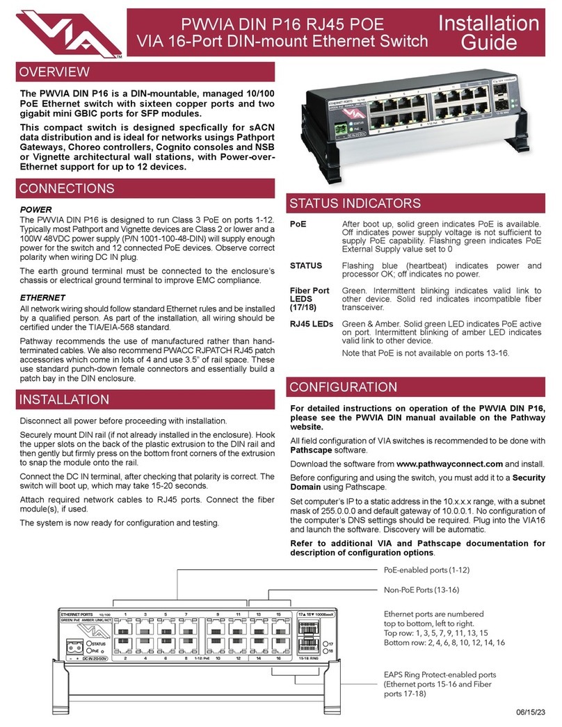
PWVIA DIN P8 RJ45 POE
VIA 8-Port DIN-mount Ethernet Switch Installation
Guide
06/15/2023
For detailed instructions on operation of the PWVIA DIN P8, please
see the PWVIA DIN manual available on the Pathway website.
All eld conguration of VIA switches is recommended to be done with
Pathscape software.
Download the software from www.pathwayconnect.com and install.
Before conguring and using the switch, you must add it to a Security
Domain using Pathscape.
Set computer’s IP to a static address in the 10.x.x.x range, with a subnet
mask of 255.0.0.0 and default gateway of 10.0.0.1. No conguration
of the computer’s DNS settings should be required. Plug into the VIA8
and launch the software. Discovery will be automatic.
Refer to additional VIA and Pathscape documentation for
description of conguration options.
The PWVIA DIN P8 is a DIN-mountable, managed gigabit
Ethernet switch with eight copper ports and two mini-GBIC
ports for SFP/SFP+ ber modules.
This compact switch is designed speccally for sACN
data distribution and is ideal for networks usings Pathport
Gateways, Choreo controllers, Cognito consoles and NSB
or Vignette architectural wall stations, with Power-over-
Ethernet support for up to 8 devices.
POWER
The PWVIA DIN P8 is designed to run Class 3 PoE on ports 1-8.
Typically most Pathport and Vignette devices are Class 2 or lower and
a 100W 48VDC power supply (PWPWR DIN TERM 100W 48VDC) will
supply enough power for the switch and 8 connected PoE devices.
Observe correct polarity when wiring DC IN plug.
The earth ground terminal must be connected to the enclosure’s chassis
or electrical ground terminal to improve EMC compliance.
ETHERNET
All network wiring should follow standard Ethernet rules and be installed
by a qualied person. As part of the installation, all wiring should be
certied under the TIA/EIA-568 standard.
Pathway recommends the use of manufactured rather than hand-
terminated cables. We also recommend PWACC RJPATCH RJ45 patch
accessories which come in lots of 4 and use 3.5” of rail space. These
use standard punch-down female connectors and essentially build a
patch bay in the DIN enclosure.
Disconnect all power before proceeding with installation.
Securely mount DIN rail (if not already installed in the enclosure). Hook
the upper slots on the back of the plastic extrusion to the DIN rail and
then gently but rmly press on the bottom front corners of the extrusion
to snap the module onto the rail.
Connect the DC IN terminal, after checking that polarity is correct. The
switch will boot up, which may take 15-20 seconds.
Attach required network cables to RJ45 ports. Connect the ber
module(s), if used.
The system is now ready for conguration and testing.
OVERVIEW
CONNECTIONS
STATUS INDICATORS
INSTALLATION
CONFIGURATION
TM
Amber LED (Link Active)
Green LED (PoE Active)
DC Power Input,
20-50V
Status LEDs Female RJ45
Gigabit Ethernet
Ports, PoE-enabled
(x8)
Mini-GBIC ports
for SFP/SFP+
Fiber modules
(x2)
Status LEDs
for SFP+
ports
IP Address Static, set at 10.x.x.x (where x is a number
between 0 and 254)
Subnet Mask 255.0.0.0
Default Gateway 10.0.0.1
VLANs Disabled (all ports run as untagged on VLAN ID
#1)
Mgmt VLAN VLAN ID#1
PoE Supply External supply value set to zero watts (PoE
effectively disabled)
Port PoE Enabled. Above value must be set >5W before a
PoE device will boot
QoS Off
Port Link Auto-negotiate
DHCP Disabled
IGMP Disabled
Art-Net Trap & Convert Disabled
Art-Net Alternate
Mapping
Enabled (only applies when above feature is
enabled)
PWVIA DIN P8 RJ45 POE
VIA 8-Port DIN-mount Ethernet Switch Installation
Guide
06/15/2023
© 2021 Acuity Brands, Inc. • One Lithonia Way, Conyers GA 30012
Pathway Connectivity | Phone: + 1 866 617 3074 www.pathwayconnect.com
APPLICATION EXAMPLE
DEFAULT SETTINGS
TM
COM
CC1
NC
NC
D1+
COM
SHLD
D1-
NC
NC
D1+
COM
SHLD
D1-
NC
NC
D1+
COM
SHLD
D1-
NC
NC
D1+
COM
SHLD
D1-
– +
24–48VDC
7WMax
SDCARD OK
PROCESSOR
IDENTIFY
Port DPort CPort BPort A
INPUT
OUTPUT
INPUT
OUTPUT
INPUT
OUTPUT
INPUT
OUTPUT
FACTORY
DEFAULT
PUSH
PUSH
Intelligent Fixtures
LED Wash Lights
Building CAT5
Ethernet
w/ PoE Ethernet w/
PoE
CAT5
Patch
Cables
PWCOG DT
PoE Lighting Console
or other DMX512 source (outputting
Network DMX)
DMX512
DMX512
Ethernet w/ PoE
PWINS RJ45EC
[xxxx]
with
PWFP G1 [xxxx]
Ethernet Wall
Plate
PWINS XLR5F
[xxxx]
with
PWFP G1 [xxxx]
DMX Output Wall
Plates
PWCHOREO
PoE Architectural Controller
NEMA Wall Enclosure
PWENC MED HOR typical
PWACC
RJPATCH
DIN RJ45 Patch
Module
PWVIA DIN P8
VIA DIN-Mount
Ethernet Switch
PWPP DIN P4
Pathport DIN-Mount
DMX/RDM Gateway
PWWSI NPOE B2 /
PWWSI LOC S2 /
PWWSI LOC S2 /
PWWSI LOC S1 /
PWFP G4
NSB Wall Station
PWWSI NPOE B4 /
PWWSI LOC S2 /
PWWSI LOC S2 /
PWWSI LOC S1 /
PWFP G4
NSB Wall Station
PWWSI NPOE B2 /
PWWSI LOC B4 /
PWWSI LOC B4 /
PWFP G3
NSB Wall Station
PWWSI NPOE B4 /
PWFP G1
NSB Wall Station
PWACC RJPATCH Q4 Pathway Accessory, DIN RJ45 patch (3.5” of rail for 4), (Qty 4)
PWPWR DIN TERM 100W 48VDC Power Supply, DIN-mount, Compression Fit Terminal, 100 Watts, 48 Volts DC
PWACC SFPP Pathway Accessory, SFP+ 850nm 10GB Ethernet Optical Transceiver
PWACC SFP Pathway Accessory, SFP 850nm 1GB Ethernet Optical Transceiver
PWVIA DIN P8 RJ45 POE
VIA 8-Port DIN-mount Ethernet Switch Installation
Guide
06/15/2023
© 2021 Acuity Brands, Inc. • One Lithonia Way, Conyers GA 30012
Pathway Connectivity | Phone: + 1 866 617 3074 www.pathwayconnect.com
ACCESSORIES
• Power input:
• Switch Only (no PoE usagee): 20-50 VDC, 10W maximum
• Full PoE Support: 48-50VDC, 130W maximum power consumption (10W for switch, 120W distributed to connected PoE devices)
• PoE Ports: Class 3 PoE available on Ports 1-8 (maximum 15.4W per port)
ELECTRICAL INFORMATION
• ANSI E1.31 sACN - Streaming streaming ACN
• IEEE 802.3 Ethernet
• IEEE 802.3af Power-over-Ethernet (with external supply)
• IEEE 802.1AB Link Layer Discovery Protocol
• IEEE 802.1Q VLAN Support
• IEEE 802.1w Rapid Spanning Tree Protocol (RSTP)
• IETF EAPS - Ethernet Automatic Protection Switching
• IETF IGMPv2 - Internet Group Management Protocol
• Dante QoS - Quality of Service
• California Title 1.81.26, Security of Connected Devices
• CE
• RoHS 2011/65/EU + A1 2015/863
COMPLIANCE
• 6.25”W x 4”H x 2.9”D (159mm x 103mm x 74mm)
• 1.05 lbs (0.47 kg)
• Operating Conditions: 14°F-113°F (-10°C to 45°C); 5-95% relative humidity, non-condensing
PHYSICAL
TM

Other VIA Technologies Switch manuals

VIA Technologies VNT5103Q28PS User manual

VIA Technologies

VIA Technologies VNT5103Q28PS User manual

VIA Technologies 6750 User manual

VIA Technologies

VIA Technologies 6750 User manual

VIA Technologies PWVIA DIN P16 User manual

VIA Technologies

VIA Technologies PWVIA DIN P16 User manual

Popular Switch manuals by other brands

NETGEAR GS105GE installation guide

NETGEAR

NETGEAR GS105GE installation guide

ADDER ADDERView Secure AVS 2114 quick start

ADDER

ADDER ADDERView Secure AVS 2114 quick start

CAMBRIONIX SyncPad54 user manual

CAMBRIONIX

CAMBRIONIX SyncPad54 user manual

Comelit IPSWP06N100A quick start guide

Comelit

Comelit IPSWP06N100A quick start guide

3Com Baseline 2816 user guide

3Com

3Com Baseline 2816 user guide

A SYSTEMS AV800HD user manual

A SYSTEMS

A SYSTEMS AV800HD user manual

Sigma 2100 Series Operator's manual

Sigma

Sigma 2100 Series Operator's manual

Link electronics 860-XL1616H Routing Switchers 860-XL1616H Specification sheet

Link electronics

Link electronics 860-XL1616H Routing Switchers 860-XL1616H Specification sheet

Leonton PT2-0702-SFP Series user manual

Leonton

Leonton PT2-0702-SFP Series user manual

Kramer ASPEN-1616UX quick start guide

Kramer

Kramer ASPEN-1616UX quick start guide

D-Link DXS-3600 Series reference guide

D-Link

D-Link DXS-3600 Series reference guide

Lenovo Flex System Fabric EN4093R user guide

Lenovo

Lenovo Flex System Fabric EN4093R user guide

ABB OKL 25 Series Installation instruction

ABB

ABB OKL 25 Series Installation instruction

Cisco EZXS55W - EtherFast 10/100 Workgroup Switch user guide

Cisco

Cisco EZXS55W - EtherFast 10/100 Workgroup Switch user guide

enika ABB 3299-11500 quick start guide

enika

enika ABB 3299-11500 quick start guide

Lindy 38043 installation guide

Lindy

Lindy 38043 installation guide

Asante IntraCore 3524 Series Getting started guide

Asante

Asante IntraCore 3524 Series Getting started guide

Extron electronics SW USB Pro Series Setup guide

Extron electronics

Extron electronics SW USB Pro Series Setup guide

manuals.online logo
manuals.online logoBrands
  • About & Mission
  • Contact us
  • Privacy Policy
  • Terms and Conditions

Copyright 2025 Manuals.Online. All Rights Reserved.