Viavi G4-20G-010-192T User manual

1
g420g010192t - 1
G4-20G-010-192T
The G4-20G-010-192T is best suited for Multi-10 Gb data centers.
G4-20G-010-192T technical specifications
System -
Deployment Multi-10 Gb data center
Base storage 192 TB
Max storage 192 TB
Lights Out Management (LOM) Yes
Redundant OS drive Yes
OS drive hot swappable Yes
OS drive size 1 TB
RAID drive hot swappable Yes
RAID version 6
Rail kit Yes
Operating system Windows 2012 R2
Physical -
Height 4U
Width 19 in
Depth 26.5 in
Weight (with mounted rail kit or portable
unit without a travel case)
116 lbs
Weight (handling or portable unit in a
travel case)
121 lbs
Media -
Monitoring interfaces 8
Speed 1/10 Gb
Accepted transceivers 1SFP/SFP+
Performance -
Aggregate performance 20 Gbps

Parts list
Power -
Redundant power supply Yes
Input frequency 50/60Hz
Input voltage 100V-240V Auto Select
Operational current (amps) 9.58
BTU/hr 3924
Operational voltage 120V
Power dissipation (watts) 1150
Relative humidity (non-condensing) 8% to 90%
Temperature (operating) 10°C ~ 35°C (50°F ~ 95°F)
Temperature (storage) -40°C to 60°C (-40°F to 140°F)
Compliance RoHS, FCC, CE
1. For SFP, the SFP may be any of Copper 10/100/1000, 1Gb SX/LX. For SFP+, the SFP+ may be any
of 10Gb SR/LR. For QSFP+, the QSPF+ may be any 40Gb SR/LR/BiDi/Universal. For QSFP28, the
QSFP28 tranceivers may be SR4, LR4, or BIDI.
Parts list
Each appliance comes packed in a box or several boxes. The boxes contain the
various components necessary for a successful installation. The G4-20G-010-192T
appliance box contains the following components:
●1 Head unit with RAID drives preinstalled
●1 Rail kit
●2 Power supply cables
●2 Ethernet cables
●1 Product Activation Information envelope containing the product
license
●1 Quick Start Guide
●SFP transceivers (if ordered)
Before installing, ensure you received all of the parts required for your system.

Quick start for experienced installers | 3
Quick start for experienced installers
First time installers should use the installation instructions on the next page.
Caution: Do not attempt in-cabinet repairs of your appliance. The appliance is very
heavy! Always use a server lift or work with a partner to install or remove the appliance
from the cabinet to perform any maintenance.
1. Mount the appliance in your cabinet. Refer to the instructions on VIAVI Rail Kit (page
10). Use a server lift if necessary. Do not remove the drives from the chassis.
2. Connect the cables.
●Power
●Ethernet
●TAP/Span
●IPMI (optional)
3. Insert the transceivers.
4. Connect the KVM.
5. Set the ip address.

4 | © 2020 Viavi Solutions (3 Feb 2020) — viavidoc.com/observerstart
G4-20G-010-192T installation
Getting your appliance installed is the first step to greater visibility of your network. This topic
covers installing your appliance in the cabinet and connecting it to your network.
Caution: Do not attempt in-cabinet repairs of your appliance. The appliance is very
heavy! Always use a server lift or work with a partner to install or remove the appliance
from the cabinet to perform any maintenance.
1. Take the appliance and all other components out of the packing materials.
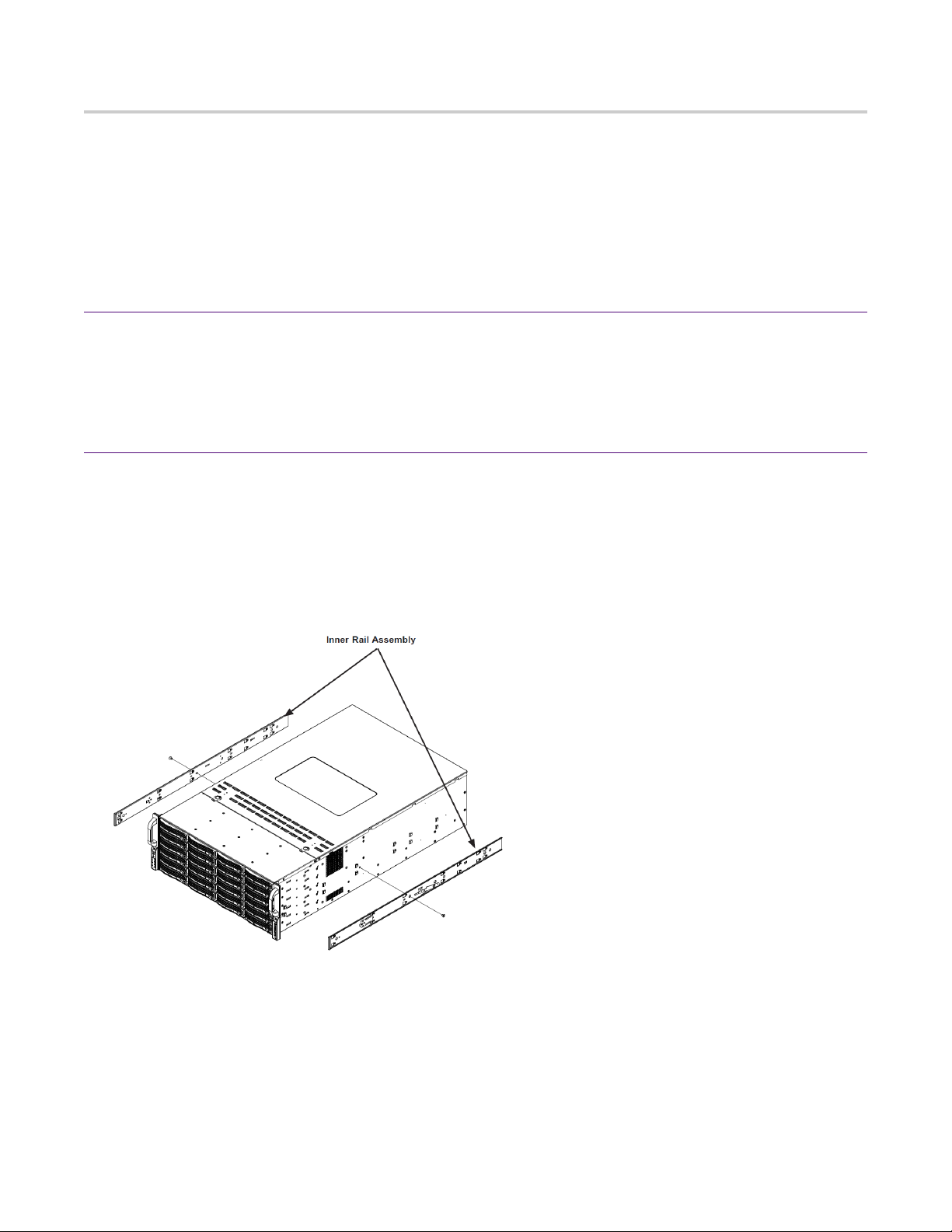
2. Install the head unit (A1) into your server rack or cabinet. Do not remove the RAID drives
from the chassis.
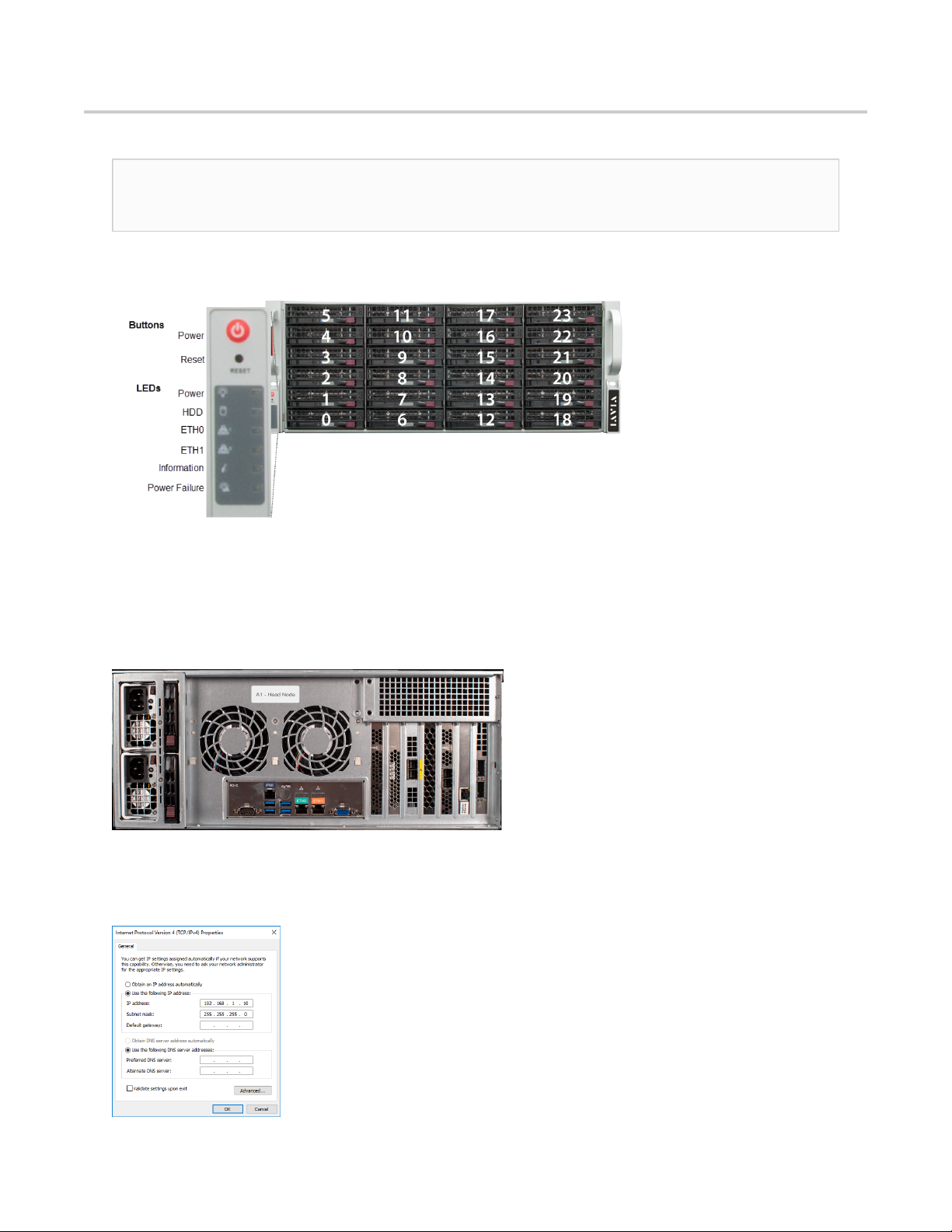
3. Using an Ethernet cable, connect the ETH0 port to the network.
Connecting the ETH0 port allows you to use Windows Remote Desktop or other tools to
control or configure Windows or Windows applications, such as Observer Analyzer.
4. (Optional) Connect an Ethernet cable from your router or switch to the LOM or IPMI port.
(Optional) A Lights Out Management or IPMI port provides you a dedicated management
channel for device maintenance. It allows you to monitor, start, stop, and manage your
appliance remotely regardless of whether the appliance is powered on.
Figure 1: G4-20G-010-192T Rear
5. Install SFP transceivers (page 6)1 into the open slots on the back of the capture card(s).
6. If you are connecting to SPAN/mirror ports of a network switch: connect a straight-through
Ethernet cable from the SPAN/mirror ports on your switch to the SFP transceivers on the
capture card.
7. Connect a monitor, keyboard, and mouse to the hardware appliance.
You can use a KVM switch if desired. (The KVM must be compatible with the operating
system used on the appliance.) The user input devices or KVM switch are only temporarily
needed to set the IP address, so you can disconnect them after the IP address is set.
8. Turn on the appliance and wait for the RAID to initialize.
After plugging in the power cords, wait until the blue Information LED starts to blink. Press
the power button once. The power button is located on the front of the appliance. The
control board initiates the power up sequence in three seconds. The entire process may take
a couple of minutes.
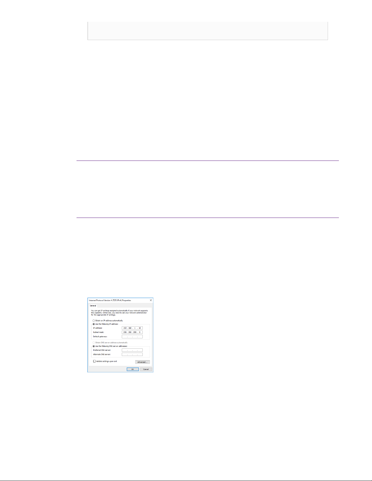
9. In Windows, change the IP address (page 7) for the ETH0 port (shown as ETH0 in
Network Connections in Windows) using information supplied to you by your network
administrator.
The default IP address (192.168.1.10) is printed on a sticker attached to the top of the
appliance.
10. Ensure the time zone settings match your environment.
11. (Optional) Change the IPMI port (page 8) in the BIOS using a static IP address provided
by your network administrator.
12. Double-click the Observer icon on the Desktop to start Observer.
Your hardware appliance is installed and on your network.
1.SFP, SFP+, QSFP+, and QSFP28 transceivers are sold separately.

G4-20G-010-192T installation | 5
Next, give the ETH0 IP address and IPMI port address, if using, to the Observer administrator.
They need the addresses to add this GigaStor probe to Observer to capture network traffic
with a probe instance.

4
g420g010192t - 6
Configuring your system
There are a number of items to do to get your system on your network and ready
to use.
Startup and shutdown
There are several procedures to turn on or off your system.
First plug in the power cord
1. Plug the power cords into the rear of the power supplies.
2. Wait until the blue Information LED starts to blink.
3. Press the power button once. The control board initiates the power up
sequence in three seconds.
After normal shutdown by IPMI or power button
Press the power button once.
After a power loss
The system will power up automatically approximately fifteen seconds after the
power returns.
Power down
Turn off the unit using a clean operating system shutdown from Windows.
1. Release the power button after blue LED stops blinking and goes dark.
2. The shutdown sequence will begin and shut down the system within ten
seconds.
How to install the SFPs
This product uses hot-swappable SFPs, but you should disconnect any cables
before changing the SFP modules.
Caution: Wear a grounding strap when handling SFPs to avoid damaging
them or other components. Avoid exposure to laser radiation from optical

How to set the IP address
components by keeping the dust plugs installed until you are ready to
install the cables.
♦Your transceivers can be inserted into any open port and in any order.
♦You can hot-swap the connected transceivers at any time, but it is
recommended you then re-launch Observer Analyzer so that the new
speeds can be identified.
Figure 2: 8-port 1/10 Gb 5U capture card port assignments
Figure 3: 2-port 40 Gb 5U capture card port assignments
Figure 4: 2U capture card port assignments
How to set the IP address
Setting the IP address ensures the hardware appliance has a visible and
permanent network presence.
Prerequisite(s):
♦A KVM switch or keyboard, monitor, and mouse are connected. The user
input devices or KVM switch are only temporarily needed to set the IP
address, so you can disconnect them after the IP address is set.
♦The IP, subnet, and gateway or router addresses are available and known
to you.
1. Log in to the Windows operating system using the Administrator account and
its default password admin.
You can change the Administrator account password after logging in. See the
Windows documentation if necessary.
2. Select Internet Protocol Version 4 (TCP/IPv4), and click Properties.
3. Set the IP address, subnet mask, router or gateway, and DNS server for your
environment and click OK.
Figure 5: Default TCP/IP settings
4. Click OK again to close the Properties dialog for that network connection.
You interact with the hardware appliance through the Apex UI.
1. Navigate to https://hostname where hostname is the IP address or DNS
name for the appliance.
2. Log into the interface using the username admin and default password
admin.

Configuring the LOM or IPMI port
Your appliance comes with an on-board LOM or IPMI port that provides you a
dedicated management channel for device maintenance. It allows you to monitor,
start, stop, and manage your appliance remotely regardless of whether the
appliance is powered on.
Prerequisite(s):
♦A GigaStor system.
♦Keyboard, monitor, and mouse or KVM attached to the GigaStor.
♦The static station IP, subnet, and gateway/router addresses are available
and known to you.
If you want to use Lights Out Management features, you must first configure
the IP address for the IPMI port from the BIOS. Then, you should change the
administrator password to something different than the default.
1. Connect an Ethernet cable from your router or switch to the IPMI or LOM
port.
2. When starting your appliance, press Delete during POST to enter the BIOS
setup.
3. In the BIOS, choose IPMI > BMC network configuration.
Figure 6: BIOS IPMI tab
4. Set Update IPMI LAN configuration to Yes.
5. Set Configuration Address source to Static.
6. Configure the Station IP address, Subnet mask, and Router address.
These values must be valid and usable on your network!
Figure 7: BIOS IPMI: IP Address configured
7. Press F4 to save your changes and to exit the BIOS setup.
The system automatically shuts down and restarts.
The IPMI port is now accessible from the IP address you chose.
Now you can log on to the IPMI web interface and change the default
password.
8. To change the default password, open a web browser to http://
<IpAddressOfIPMIport>, and log on with the user name ADMIN and password
ADMIN in caps.
IpAddressOfIPMIport is the station IP address you configured in step 6. The
user name and password boxes are always case-sensitive.
9. Choose Configuration > Users, and select the second user account (ADMIN
account).
10. Click Modify User, and change the password.
11. (Optional) Set up alerts.
There is no audible alarm if there is an issue with a power supply unit. Other
alerting options are available. Each must be configured separately using
details from your environment.

Configuring the LOM or IPMI port
●To receive email alerts, change the settings at Configuration > SMTP.
●To receive SNMP traps, change the settings at Configuration > SNMP.
●To receive Syslog messages, change the settings at Configuration >
Syslog.
You configured the IPMI port and changed the default password. You may have
also configured your system to send alerts when certain situations arise.

10 | © 2020 Viavi Solutions (3 Feb 2020) — viavidoc.com/observerstart
VIAVI Rail Kit
Decide on a suitable location for the rack unit that will hold your chassis. It should be a
clean, dust-free area that is well ventilated. Avoid areas where heat, electrical noise and
electromagnetic fields are generated. A nearby grounded power outlet is required.
How to attach the rails
Rail assemblies must be attached to the chassis and rack before inserting the system into your
rack.
Prerequisite(s):
The box your chassis was shipped in should include:
♦two sets of rail assemblies
♦two rail mounting brackets
♦mounting screws and washers to mount the system into the rack
This rail will fit a rack between 26.5" and 36.4" deep.
1. Identify the inner rack rails.
The chassis package includes one pair of rack rail assemblies in the rack mounting kit.
Each assembly consists of an inner rail that secures to the chassis and an outer rail that is
attached directly to the rack. The inner rails are etched with “L” (Left side) and "R" (Right
side). The rail is on the correct side and mounted correctly if the lettering if face-up.
Figure 8: Rail kit inner assemblies
2. Identify the left and right side inner rails. Place the correct inner rail on the side of the
chassis, aligning the hooks of the chassis with the inner rail holes. Make sure the rail faces
"outward" so that it will fit with the rack's mounting bracket.
3. Slide the rail toward the front of the chassis to hook the inner rail onto the side of the
chassis.
4. (Optional) If desired, secure the rail with two flat head M4 x 4mm screws (and washers) as
illustrated.
5. Repeat for the other inner rail.

How to install the system into your rack | 11
Figure 9: Installing the inner rails
6. Identify the outer rack rails.
7. Press upward on the locking tab at the rear end of the middle rail.
8. Push the middle rail back into the outer rail.
9. Hang the hooks on the front of the outer rail onto the square holes on the front of the rack.
If desired, use screws (and washers) to secure the outer rails to the rack.
10. Pull out the rear of the outer rail, adjusting the length until it just fits within the posts of
the rack.
Figure 10: Extending and mounting outer rails
11. Hang the hooks of the rear section of the outer rail onto the square holes on the rear of the
rack. Take care that the proper holes are used so the rails are level. If desired, use screws
(and washers) to secure the rear of the outer rail to the rear of the rack.
12. Repeat for the other outer rail.
The rails are attached.
Next, insert the server into the rack.
How to install the system into your rack
This section provides information on installing a chassis into a rack unit with the rails provided.
There are a variety of rack units on the market, so the assembly procedure may differ slightly.
Also refer to the installation instructions for your rack unit.

12 | © 2020 Viavi Solutions (3 Feb 2020) — viavidoc.com/observerstart
Caution: Do not pick up the server by the front handles. They are designed to pull the
system from a rack only.
1. Align the chassis rails with the front of the rack rails.
2. Slide the chassis rails into the rack rails, keeping the pressure even on both both sides. You
may have to depress the locking tabs while inserting. When the server has been pushed
completely into the rack, the locking tabs should "click" into the locked position.
3. If screws are used, tighten the screws on the front and rear of the outer rails.
4. (Optional) Insert and tighten the thumbscrews that hold the front of the server to the rack.
How to remove the server from the rack
Caution: It is dangerous for a single person to off-load the heavy chassis from the rack
without assistance. Be sure to have sufficient assistance supporting the chassis when
removing it from the rack. Use a server lift.
1. Pull the chassis forward out the front of the rack until it stops.
2. Press the release latches on each of the inner rails downward simultaneously and move the
chassis forward in the rack.
Figure 11: Removing the server from the rack
Technical Support
Please contact technical support if your issues are not represented or you need further help.
North America +1 800 526 7919
South America +1 800 526 7919
EMEA +44 1 959 569 880
APAC +44 1 959 569 880
All Other Regions viavisolutions.com/contacts
email nisupport@viavisolutions.com (North/South America)
uknisupport@viavisolutions.com (EMEA/APAC)
Support hours are 7:00 A.M. to 7:00 P.M. CST/CDT (for North and South America) and 8:00 A.M.
to 5:00 P.M GMT (EMEA and APAC).
Table of contents
Other Viavi Server manuals

Viavi
Viavi G4-60G-010-576T User manual

Viavi
Viavi G4-Apex-ENT-80T User manual

Viavi
Viavi G4-ObserverONE User manual

Viavi
Viavi G4-40G-100-384T User manual

Viavi
Viavi G3-GS-8P-576T Manual

Viavi
Viavi G3-GS-8P-288T Manual

Viavi
Viavi Gen2 GigaStor Manual

Viavi
Viavi G4-GigaFlow User manual

Viavi
Viavi G4-PT-010-8T Manual

Viavi
Viavi G4-10G-010-96T User manual