Vibration Research VibrationVIEW User manual

VibrationVIEW
VIBRATION CONTROL
QUICK START
GUIDE

Quick Start Guide
Thank you for purchasing from Vibration Research (VR). We appreciate
your business! VR is continually upgrading the features and capabilities
of our products. Please visit our website regularly to download the latest
available VibrationVIEW software.
This guide provides a quick and basic introduction to the software and is
not intended to replace the VibrationVIEW Software Manual. For optimal
system settings and troubleshooting and safety precautions, please refer to
the Hardware Manual packaged with your product or the digital Help file.
If you have questions regarding your system, please contact your Vibration
Research representative or our product support staff.
+1.616.669.3028 8am to 5pm Monday-Friday (EST)
support@vibrationresearch.com
VibrationResearch.com
© 2021 Vibration Research is a registered trademark in the United States and other countries.
Vibration Research®| VibrationVIEW®| ObserVR1000®| ObserVIEW®

Table of Contents
Setting up the Hardware
ObserVR1000.....................2
VR9500 ............................. 4
VR10500 ............................6
Establishing PC Communication............... 9
Input Configuration ................................. 12
System Limits......................................... 12
System Check........................................ 13
SineVIEW Test Set-up............................. 15
RandomVIEW Test Set-up ...................... 18
ShockVIEW Test Set-up.......................... 20
FDRVIEW Test Set-up............................. 22
Multi-Axis Test Set-up............................. 24
Automatic Report Generation ................. 26
Troubleshooting Connection Errors......... 28
Tips & Tricks........................................... 30
Important Changes to VibrationVIEW...... 23
Key Mapping .......................................... 34

2 • VibrationVIEW Quick Start Guide
Setting Up The Hardware
ObserVR1000 | Connecting the Unit
Set up the computer in the conventional configuration with
power cables, mouse, keyboard, and monitor.
To connect one ObserVR1000 unit:
1. Connect the ObserVR1000 network port to the dedicated network
card on the computer using an Ethernet cable (included).
2. Connect the external battery charger to the ObserVR1000 for
uninterrupted power.
3. Connect the amplifier’s input to the OUT connector on the rear panel
of the ObserVR1000.
4. Connect an accelerometer to channel 1 on the front panel. Other
accelerometers can be connected to channels 2 to 16.
5. Turn on the ObserVR1000.

support@vibrationresearch.com • 3
ObserVR1000 | Connecting Multiple Units
Set up the computer in the conventional configuration with power cables,
mouse, keyboard, and monitor.
To connect multiple ObserVR1000 units using a network switch:
1. Connect the first ObserVR1000 (channels 1-16) to any port on the
switch. Connect the additional ObserVR1000 units to the sequential
ports.
2. Connect the PC to any available port with the Ethernet cable
(included).
3. Connect the external battery chargers (included) to each
ObserVR1000 unit for uninterrupted power.
4. Connect the shaker amplifier’s input to the OUT connector on the
first ObserVR1000.
5. Connect sensors to front analog inputs; 128 inputs maximum.
6. Turn on the ObserVR1000 units.

4 • VibrationVIEW Quick Start Guide
Setting Up The Hardware
VR9500 | Connecting the Unit
Set up the computer in the conventional configuration with power cables,
mouse, keyboard, and monitor.
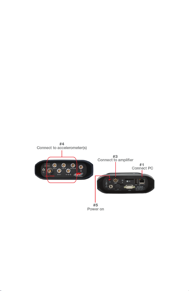
To connect one VR9500 unit:
1. Connect the VR9500 network port to the dedicated network card on
the computer using an Ethernet cable (included).
2. Connect the power cord to the VR9500. The power input will
automatically switch for voltage 90VAC to 250VAC and 50/60 Hertz.
3. Connect the shaker amplifier’s input to the Drive output connector on
the rear panel of the VR9500.
4. Connect an accelerometer to channel 1 on the front panel. Other
accelerometers can be connected to channels 2, 3, and 4.
5. Turn on the VR9500.
Video: Setting Up Your System
Scan this QR code with your smart device camera.
vibrationresearch.com/resources/setting-up-your-vr9500-control-system

support@vibrationresearch.com • 5
VR9500 | Connecting Multiple Units
Set up the computer in the conventional configuration with power cables,
mouse, keyboard, and monitor.
To connect multiple VR9500 units using a network switch:
1. Connect the first VR9500 (channels 1-4) to any port on the switch.
Connect the additional VR9500 units to the sequential ports.
2. Connect the PC to any available port with the Ethernet cable (included).
3. Connect the AC power cords (included) to the VR9500 units.
4. Connect the shaker amplifier’s input to the Drive output connector on
the first VR9500. For systems controlling two shakers simultaneously,
connect the second shakers’s amplifier input to the COLA output
connector on the first VR9500.
5. Connect the sensors to front analog inputs; 128 inputs maximum.
6. Turn on the VR9500 units.

6 • VibrationVIEW Quick Start Guide
Setting Up The Hardware
VR10500 | Connecting the Unit
Set up the computer in the conventional configuration with power cables,
mouse, keyboard, and monitor.
To connect one VR10500 unit:
1. Connect the VR10500 network port to the dedicated network card
on the computer using an Ethernet cable (included).
2. Connect the power cord to the VR10500. The power input will
automatically switch for voltage 90VAC to 250VAC and 50/60 Hertz.
3. Connect the shaker amplifier’s input to the Drive output connector on
the rear panel of the VR10500.
4. Connect an accelerometer to channel 1 on the front panel. Other
accelerometers can be connected to channels 2 to 16.
5. Turn on the VR10500.

support@vibrationresearch.com • 7
VR10500 | Connecting Multiple Units (up to 3 units)
Set up the computer in the conventional configuration with power cables,
mouse, keyboard, and monitor.
To connect up to three VR10500 units using an internal integrated switch:
1. Connect the first VR10500 (channels 1-16) network port to the
dedicated network card on the computer using an Ethernet cable
(included). Up to two additional VR10500 units can be connected to
the expansion network port(s).
2. Connect the AC power cords (included) to the VR10500 units.
3. Connect the shaker amplifier’s input to #1 Drive output connector
on the first VR10500. For systems controlling multiple shakers
simultaneously, connect the additional shaker’s amplifier inputs to the
remaining Drive output connector on the first VR10500.
4. Connect sensors to front analog inputs; 48 inputs maximum.
5. Turn on the VR10500 units

8 • VibrationVIEW Quick Start Guide
Setting Up The Hardware
VR10500 | Connecting Multiple Units (4+ units)
Set up the computer in the conventional configuration with power cables,
mouse, keyboard, and monitor.
To connect four or more VR10500 units using a network switch:
1. Connect the first VR10500 (channels 1-16) to any port on the switch.
Connect the additional VR10500 units to any available port.
2. Connect the PC to any available port with the Ethernet cable (included).
3. Connect the AC power cords (included) to the VR10500 units.
4. Connect the shaker amplifier’s input to #1 Drive output connector
on the first VR10500. For systems controlling multiple shakers
simultaneously, connect the additional shaker’s amplifier inputs to the
remaining Drive output connector on the first VR10500.
5. Connect the sensors to front analog inputs; 256 inputs maximum.
6. Turn on the VR10500

support@vibrationresearch.com • 9
2
3
Establishing PC Communication
Configuring the I/O Unit
1. To set up the dedicated network card for VibrationVIEW, first
right click the Start Button > Network Connections
2. Choose option Change adapter options
3. Right Click on the network card attached to the I/O unit and
select Properties
...continued on next page

10 • VibrationVIEW Quick Start Guide
4
Establishing PC Communication
Configuring the I/O Unit continued
4. Disable all the options except Internet Protocol Version 4 (TCP/IPv4)
5. From the Internet Protocol (TCP/IP) Properties dialog box, select
Properties. Assign IP address 192.168.3.10 and subnet mask
255.255.255.0
• If multiple network cards are installed in the computer the IP address can be adjusted.
Other recommended values are 192.168.2.10 and 192.168.4.10, although any Class
C or Class D subnet will work.
• Click the OK button to return to the previous dialog box
6. From the Properties dialog box, click the Sharing tab. Make sure
Internet Connection Sharing for this connection is disabled/unchecked.
5
6

support@vibrationresearch.com • 11
Connecting to VibrationVIEW
VibrationVIEW must be configured to use the appropriate network
connection after the network is setup.
1. Start VibrationVIEW by double-clicking the VibrationVIEW icon on the
desktop. Select Configuration > Hardware from menu command
2. Select the network card previously configured. Typically this will be
192.168.3.10. Select Probe. Click the Apply button.
3. Your I/O unit serial number will be added to the drop down menu for
channels 1-4 when it initially connects to the computer.
• Select the appropriate I/O unit serial number to configure channels 1-4, and optionally,
channels 5-8, channels 9-12, and 13 through 128 (in blocks of 4 channels). The I/O
unit control boxes are assigned addresses from the range listed in the Control Boxes
Address parameters. This does not need to be changed.
1
3
2

12 • VibrationVIEW Quick Start Guide
Input Configuration
Setting Sensitivities for Inputs
The inputs must be
configured for each
connected accelerometer.
Each input can be
configured as single ended
or differential and, optionally,
as capacitor coupled.
Single ended inputs can
also provide a constant
current source to power
your accelerometers. Other
types of accelerometers
such as charge coupled
accelerometers require external conditioning. Be sure to enter the proper
conditioner calibration factor in the Advanced Settings option from the
Inputs tab.
To view/edit more information on an accel, click the Advanced Settings
button. If the connected accelerometer has TEDS (Transducer Electronic
Data Sheet) containing the calibration information, simply click the TEDS
checkbox and the information will automatically be entered when you
click Read All TEDS. When the appropriate values are entered, click
the OK button. The new accelerometer sensitivity factors will take effect
immediately.
Note: Be sure to check the Accel Power box if you want the I/O unit to provide the constant
current source to your accel.
System Limits
Shaker Limits and Moving Mass
Before every test, the I/O unit checks the system specifications to
determine if it can be performed within system limits. The shaker force,
velocity, and displacement limit values only need to be entered once when
the system is first configured. The fixture and product masses that are
required to properly compute the acceleration limits of the shaker must be
entered every time the fixture or product mass is changed.

support@vibrationresearch.com • 13
To set the system limits, select the Configuration > System Limits menu
command. In the dialog box, either select the shaker model matching
your setup or select User Defined Limits to enter the specifications of your
shaker system. These specifications should be listed in the manual for your
shaker system.
Enter the Moving Mass for
all the shaker parts on your
system. If your system does
not have one of the listed
parts, enter zero for that item’s
mass. The sum of these mass
values is used to calculate
the maximum operating
acceleration for your system
using Newton’s law:
Force = mass *acceleration
Once all specifications are entered, be sure to click Apply (choose yes to
reset the system)
System Check
Verify Inputs and Outputs
Perform the following procedure to verify that the input and output levels
and frequencies are correct:
1. Select Test > Test Type > System Check to check menu command
to switch the system into System Check mode
2. Select
Configuration > Inputs menu command. Verify that your
accelerometer sensitivity and power source settings are configured
appropriately. The accelerometer power is enabled in this dialog box.
If you are using constant current accelerometers or a conditioner that
requires a constant current source make sure the Accel Power is
checked. Click the OK button.

14 • VibrationVIEW Quick Start Guide
System Check continued
3. In the System Check Control Center enter
the default values:
• Electro Dynamic shakers
frequency of 30Hz
displacement of 0.1in (peak-to-peak)
• Servo Hydraulic shakers
frequency of 20Hz
displacement of 0.5in (peak-to-peak)
4. Verify that the input levels are near zero
(double right-click on the graph to auto scale).
5. Click the Start button. The
output level should slowly ramp
up until the shaker approaches
a 0.1-inch peak-to-peak
displacement (0.5 inches if
using the Servo Hydraulic
recommended set-up)
• If the shaker does not move, click
the Stop button to turn the output
off. Verify that the Drive output
connector from the I/O unit is connected to the shaker amplifier’s input, that the amplifier
is turned on (and gain is up), and that the amplifier output is connected to the shaker.
Return to step 4.
• If the shaker still does not move, connect the Drive output connector of the I/O unit to
an oscilloscope or true RMS voltmeter, set the output voltage level to 0.5 volts (0-to-
peak) and verify that you have a 0.5 volt (0-to-peak) amplitude reading (0.35 volts
RMS). If the Drive output connector is not measuring 0.35 volts RMS, your system
may require calibration.
TIPS
If the shaker vibrates, but the input waveform remains flat, click the Start button a second
time so that the text on the Start button is dark and the output stops ramping up. Check the
accelerometer cables to verify that they have good connections and that the accelerometer
conditioning equipment is turned on. If you are using the internal current source to power the
accelerometer, verify that Accel Power on Configuration > Inputs dialog box is checked.
If there is still no input signal, connect the conditioned accelerometer signal to an oscilloscope
or voltmeter and verify that you see a voltage reading. If there is no reading, click the Stop
button to turn the output off, replace the accelerometer cable, accelerometer, and/or the
accelerometer conditioning equipment with devices known to be working and return to step 4.
NOTE: most problems are due to bad cable connections.

support@vibrationresearch.com • 15
SineVIEW Test Setup
Entering a Sine Test
Select Test > Define New Test > Sine Test
• Simple Test Mode is enabled by default
• To disable Simple Test mode, select the Configuration > Parameters
menu option and uncheck Define new tests as Quick Tests. Select
Apply > OK. Close Sine test and reopen for change to take effect.
This section will guide you through a series of Advanced configuration
dialog boxes for Sine. Default values will be supplied for all parameters.
If you are unsure about a parameter, use the default value (click the Help
button in the lower right corner of the Settings window for specific Help
information). After all the values for each dialog tab are entered, click the
next tab to advance to the next set of information for setting up the test.
shaker vibrating with 0.1" displacementshaker still
6. Once you get both an output and an input signal, use a displacement
measurement tool (Example A) to verify that the shaker peak-to-peak
displacement matches the value shown in the System Check Control
Center. If it does not match, select the Configuration > Inputs menu
command to verify that the accelerometer sensitivity settings match the
calibrated values for the accelerometers you are using.
NOTE: To use the V Scope Displacement Measurement Tool – tape or hold firmly on shaker
head so that it moves in the direction of vibration (see arrows). The lines will blur and intersect
at the 0.1 inch mark on the measurement tool if the shaker is moving as directed above (0.5
for the servo hydraulic set-up). If the lines don’t intersect there, check that your accelerometer
sensitivities are set correctly (and power source on, if required).
Example A

16 • VibrationVIEW Quick Start Guide
SineVIEW
PROFILE
The amplitude and frequency
breakpoints and the desired control
parameters (acceleration, velocity, or
displacement) for the test are entered
here. Use the Insert and Delete
buttons to add or remove segments.
The small arrow next to the numbers
on the left of the window indicates
the current insertion/deletion point. A
test may be composed of over 1000
segments.
SCHEDULE
The duration of the test segments
are entered here. Durations may be entered in time duration, number of
sweeps, or number of cycles. The test schedule is also used to schedule
sweeps scaled to different amplitude levels and to select one or more fixed
frequency tones.
SWEEP
The sweep rate is entered here. Enter the sweep rate and click the drop
box to select the desired units.
PARAMETERS
The feedback control parameters for the test are entered here. For most
tests, the parameters may be left at their default values. In some cases
(such as when the control accelerometer sees a large resonance), these
values will need to be tuned.
LIMITS
The tolerance and abort limits for the
test are entered here. The control
tolerance and abort limits apply to the
control signal. If monitoring channels
are being used, enable the appropriate
channels in the Sine Channels dialog
box and enter the plus and minus
abort limits for the monitor channel. All
limits are measured in dB, or percent,
relative to the demand signal at the
active frequency.

support@vibrationresearch.com • 17
LIMITS continued
The tolerance lines are reference lines shown on the graphs (brown dashed
lines) and are used to determine when the I/O unit goes from Start to
Run mode when starting a test (Yellow during Starting) (Green when
Running).
The Plus and Minus aborts are limits that, when exceeded, cause the test
to abort. The control abort lines are shown on the graphs as solid red lines.
The maximum output voltage limits, both absolute (Max Output parameter)
and relative to the measured acceleration level (Max System Gain
parameter) are also entered here. These parameters are safety limits that
will cause the test to abort when something goes wrong (for example,
when an accelerometer cable comes loose.)
Refer to the How to tune Sine I/O unit parameters section in the Help File
for more information on how to determine the appropriate Max Output and
Max System Gain parameters for your
test.
CHANNELS
The control channels for the test are
selected here. They can be combined
using one of four methods. A tracking
filter can be selected for any channel.
DATA STORAGE
The directory into which the data from
this test will be stored is selected here.
Data can be automatically stored on
a regular time interval, at the end of
each level (levels are defined using the
Schedule dialog box) and at the end of
the test. Select the check boxes for your desired data storage times and
enter the desired interval times.
At this point the test definition is complete. Select OK to close the dialog
box. You will be asked if you want to save the test definition to the
hard drive. Select Yes; enter the desired name and select Save to save the
test.
To access parameters for specialized tests, select the Test > Edit Test
Settings menu command (or use the toolbar button Settings) and click the
Resonance, Notching, or Step Test tabs.

18 • VibrationVIEW Quick Start Guide
SineVIEW continued
Additional Tips & Tricks
To show a large display of
frequency and input readings,
select View > Big Display
(Ctrl+B).
• Click Enable Manual
Controls to manually
control the frequency and
amplitude of the sine tone
• Left mouse click on
frequency will toggle
sweep down. Double-click frequency steps to integer Hz values
• Right mouse click on frequency will toggle sweep up. Double-click
frequency steps to integer Hz values
• Mouse scroll wheel increases or decreases the dB level of the test.
When defining the sweep rate in sine, you can change the sweep
rate from “oct/min” to “min/sweep (Logarithmic)” to see how long one
sweep will take.
RandomVIEW Test Setup
Entering a Random Test
Select Test > Define New Test > Random Test
• Simple Test Mode is enabled by default.
• To disable Simple Test mode, select the Configuration >
Parameters menu option and uncheck Define new tests as Quick
Tests. Select Apply > OK. Close Random test and reopen for
change to take effect.
This section will guide you through a series of Advanced configuration
dialog boxes for Random. Default values will be supplied for all parameters.
If you are unsure about a parameter, use the default value (click the Help
button in the lower right corner of the Settings window for specific Help
information). After all the values for each dialog tab are entered, click the
next tab to advance to the next set of information for setting up the test.
Table of contents
Other Vibration Research Recording Equipment manuals