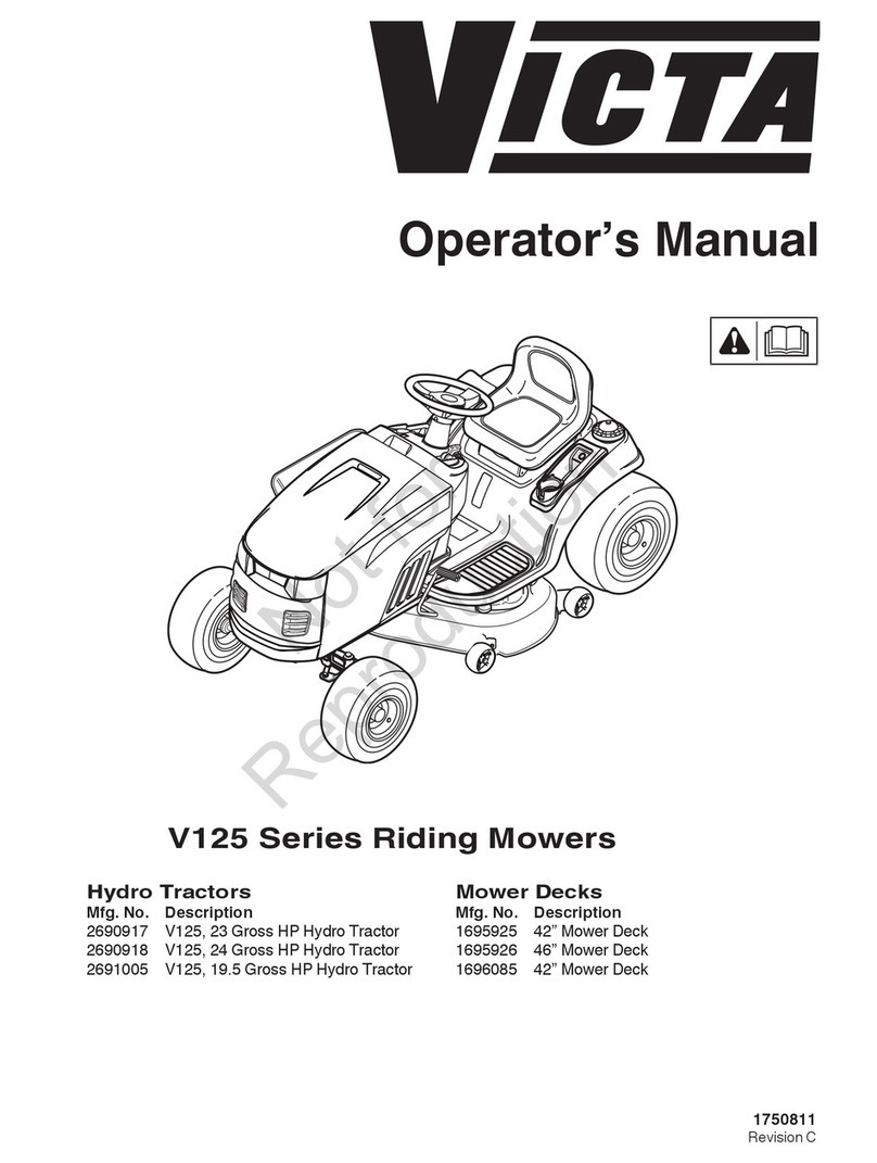
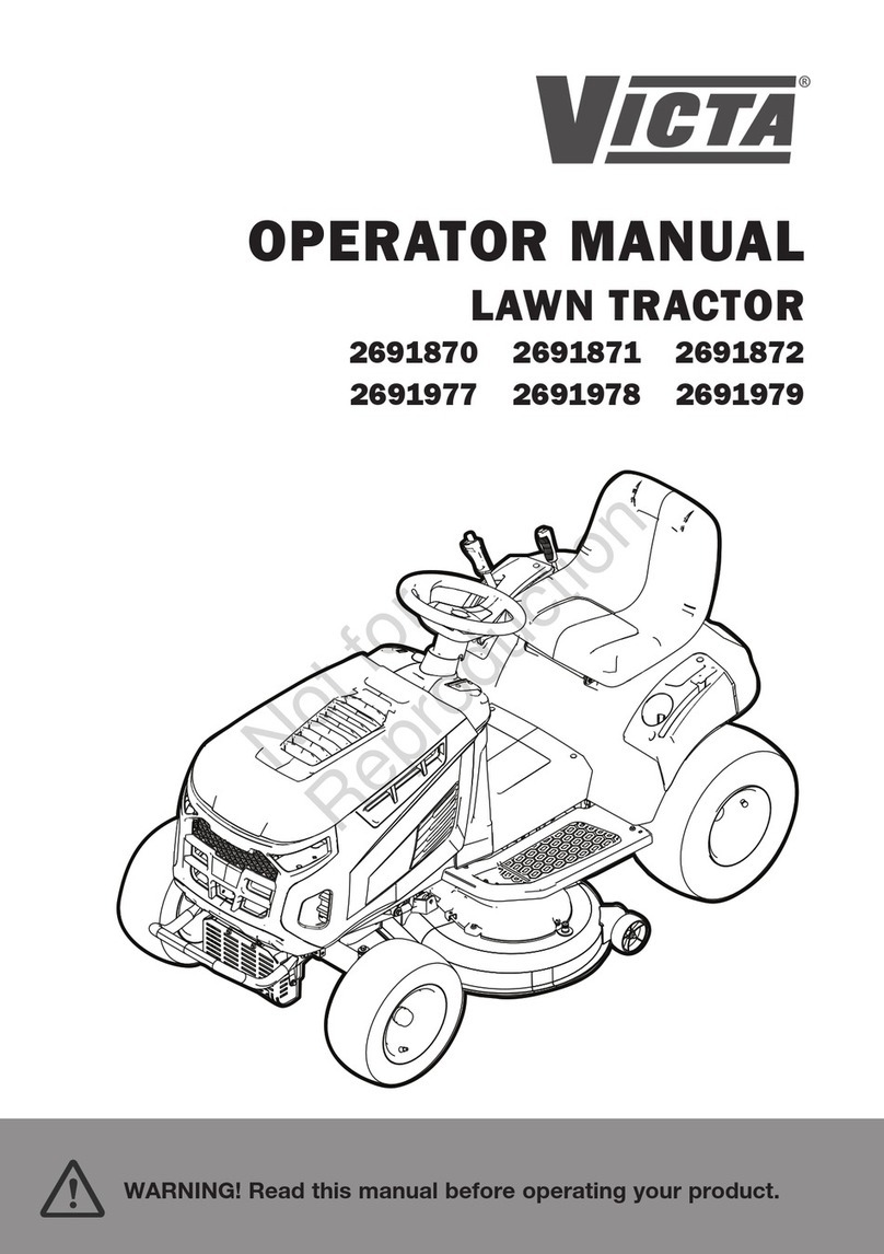
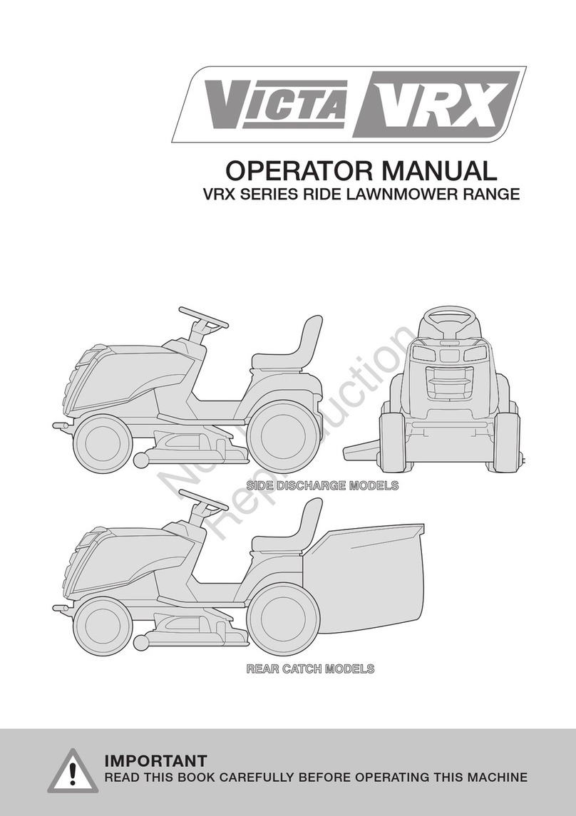
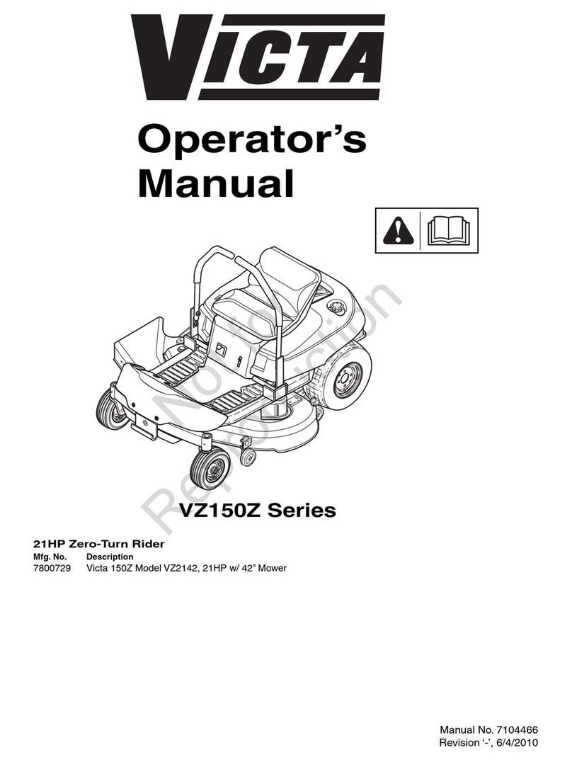
Victa PRO Series Manual

· . .
."-- '
..
r
RIDE
ON
MOWERS
OWNER'S
MANUAL
AND
OPERATING
INSTRUCTIONS

II!eTA
ITISESSENTIALTOREADANDUNDERSTAND THESEINSTRUCTIONS BEFOREUSINGMOWER
SAFETV
INSTRUCTIONS
FOR
RIDE-ON
MOWER
VICTA IS VERY SAFETY CONSCIOUS WHEN DESIGNING AND MANUFACTURING CONSUMER PRODUCTS
FOR THE SAFETY OF YOURSELF AND OTHERS·FOLLOW THESE SAFETY INSTRUCTIONS
THE RIDE ON MOWER IS A POTENTIALLY DANGEROUS MACHINE.
AT
NO
t
OOl
WARNING TIME SHOULD MORE THAN ONE PERSON SIT OR RIDE ON THE MACHINE.·
IT IS RECOMMENDED
THAT
NO CHILDREN OPERATE THE MACHINE.
Know your controls and how to stop quickly - READ THE
OWNER'S MANUAL.
DO NOT ALLOW CHILDREN TO OPERATE MOWER. DO
NOT ALLOW ADULTS TO OPERATE
MOWER
WITHOUT
PROPER INSTRUCTIONS.
DO NOT carry passengers or give rides. Keep children, pets
and bystanders out of the mowing area.
Only
the
operator
should
ride
on
the
mower
and
only
ride
on
the
seat.
NEVER OPERATE MOWER IN BARE FEET, SANDALS OR
SNEAKERS. Wea r sturdy rough -soled work shoes.
DO NOT allow
anyone
to operate mower while intoxicated or
while taking medication that may impair their senses or
reactions.
CHECK overhead clearance carefully before driving under
power lines, guy wires , bridges or low hanging tree branches,
entering or leaving buildings, or inany othersituation where the
operator may be struck or pulled from the mower, which could
result in serious injury.
ALWAYS WEAR SUITABLE EYE PROTECTION WHEN
OPERATING A MOWER.
To maintain control of the mower and reduce the possibility of
upset or collision, operate the mower smoothly. Avoid erratic
operation and excessive speed .
KEEP AREA OF OPERATION CLEAR OF ALL PERSONS
PARTICULARLY SMALL CHILDREN AND PETS. STOP THE
ENGINE WHEN THEY ARE IN THE VICINITY OF YOUR
MOWER. Although the area should be completely cleared of
foreign objects, small objects might have been overlooked and
could be accidentally thrown by the
mower
in any direction
causing serious injury.
When crossing gravel drives, walk s or roads disengage the
blade(s) and raise cutter deck to max. height.
DO NOT PUT HANDS OR FEET NEAR OR
UNDER
ROTATING PARTS. Keep clear of the discharge opening at all
times as the rotating blade(s) can cause injury .
Disengage power to attachment(s) and stop engine befure
making any adjustments or repairs. Disconnect spark plug lead
from spark plug.
BEFORE ATTEMPING TO UNCLOG THE DISCHARGE
CHUTE, STOP THE ENGINE. The
mower'
blades may
continue to rotate for a few seconds after the engine has been
switched off. Therefore be sure the blade(s) have stopped
completely. Remove key from ignition to prevent accidental
starting.
Take all possible precautions when leaving mower unattended
. such as setting parking brake , stopping engine and removing
key from ignition.
DO NOT stop or start suddenly when going uphill or downhill.
Mow up and down face of steep slopes: never across the face .
. EXERCISE EXTREME CAUTION if it is necessary to
drive the mower up an incline or back the mower down an
incline because the front of the mower could lift and rapidly flip
over backward which could cause serious injury.
(MAXIMUM
ANGLE
OF
SLOPE
IS 15 DEGREES).
• REDUCE ENGINE
SPEED
ON
SLOPES
AND IN SHARP
TURNS
TO
PREVENT
TIPPING OR LOSS OF
CONTROL
.
• ALL
CHANGES
OF
SPEED
AND DIRECTION TO BE
MADE
SMOOTHLY
AND
PROGRESSIVELY
. Sudden changes in
direction can be
dangerous
and
will
affect
the
life
of
the
transmission.
• Stay alert for holes in terrain and other hidden hazards.
• Do not turn sharply. Use care when reversing.
• Look out for traffic when crossing or near roadways.
• When using cutters, never direct discharge of material towards
bystanders nor allow anyone near mower Nhile in operation.
• Handle petrol with care, it is highly flammable.
• Use approved petrol container.
•
NEVER
removefuel cap or add petrol to a running or hot engine
or fill tank indoors. Wipe up spilled petrol.
• DO NOT run engine indoors as exhaust fumes are dangerous.
• Keep the mower and attachments in good operating condition,
and keep safety devices in position.
• Keep all nuts, bolts and screws tight to be sure the equipment
is in good working condition.
• NEVER store the mower with petro l in the tank
insidea
building
where fumes may reach an open flame or spark . Allow engine
to cool before storing in any enclosure.
• To reduce fire hazard, keep the engine free of grass , leaves or
excessive grease.
• The mower and equipment should be stopped and inspected
for
damage
after striking any hard or foreign object. The
damage must be repaired before rostar
tlnq
and operating the
equipment.
DAMAGED
BLADES
AND
WORN
BOLTS
ARE
MAJOR
HAZARDS.
Always
replace
worn
or
damaged
blades
in
sets
to
preserve
correct
balance.
• DO NOT change the engine governor settings.
• Check the blade mounting bolts at frequent intervals for proper
tightness.
• NEVER drive the mower up a ramp onto a trailer or truck,
because the mower could tip over, causing serious personal
injury. The
mower
must be pushed manually to load properly.
• REPLACE
DAMAGED
OR
FAULTY
MUFFLERS
.
"-,eTA
LOOSE
PARTS
KIT
[ALL
MODELS]
DESCRIPTION QTY USE
Steering Wheel
Roll Pin
Ignition Keys
Battery Pack (HANDLE WITH CARE)
.
.
.
..
1
1
2
1
..
.
.
.
On steering wheel
Securesteering wheel to shaft
To startengine
Battery
SETTING
UP
INSTRUCTIONS
STEERING
WHEEL
HOLE
-:
ROLL
PIN
STEERING
WHEEL
INSTALLATION
- FIG 1
INSTALLING STEERING
WHEEL
1. Slip the steering wheel over steering shaft and align wheel hole
over shaft hole.
2. Insert roll pin into the holes and drive through wheel and shaft
until 2mm protrudes each side.
INSTALLING
THE
BATTERY
1. Remove the battery from inside the bonnet as follows :-
• (a) undo bonnet straps on both sides of mower, and lift bonnet
up.
• (b) remove cable terminals from battery.
• (c) remove nyloc nuts and remove clamp bar.
2. Fill battery with Electrolyte.
This should be done as follows
DANGER
Battery
acid
must
be
handled
with
care.
Keep
sparks,
flames
and
cigarettes
away.
Charge
in
VENTILATED
area.
1. Remove filler caps from battery and slowly pour in acid. Fill to
a level that covers the plates.
2. Allow battery to stand 1/2 hour.
3. Rockbatteryto disperse bubbles and top-up to itsoriginal level.
4. Charge battery at a constant rate of 4 amps for 3 hours
connecting the red positive (+)lead of chargerto (+)terminal
of battery and black negative (
-)
lead of the charger to
(-)
terminal of battery.
CHECK
ALL
CELLS
AFTER
CHARGING
BATTERY
INSTALLATION
- FIG 2
5. Replace filler caps.
6. Wash away any spilt acid with water and wipe dry.
7. Place battery inside bonnet and secure with clamp bar.
8. Install the positive (red) cable to the
(+)
terminal and the
negative (black) cable to the
(-
) terminal. Secure for good
electrical contact.
9. Close bonnet.
WARNING
KEEP
BATTERIES
OUT OF
REACH OF
CHILDREN
FIRST
AID
TREATMENT
FOLLOW
THESE
INSTRUCTIONS
CAREFULLY
IF
ACID
SHOULD
COME
INTO
CONTACT
WITH
CLOTHING
OR SKIN.
EXTERNAL
CONTACT
:-
IMMEDIATELY
FLUSH
SKIN
OR
CLOTHING
WITH
WATER.
INTERNAL:-
'DRINK
LARGE
QUANTITIES
OF
WATER
OR
MILK
. DO NOT
INDUCE VOMITING.
SEEK
IMMEDIATE
MEDICAL
ATTENTION.
EYES:-
FLUSH
WITH
COOL
WATER
FOR AT
LEAST
15 MINUTES,
THEN
SEEK
IMMEDIATE
MEDICAL
ATTENTION.

FILL CRANKCASE WITH OIL.
The ride-on mower is delivered
without
oil
in the crankcase. Oil
must
be
added
before
attempting
to
start
eng
ine.
1. Place ride-on mower on level ground and
open
the bonnet.
2. Unscrew and remove dipstick from oil filler tube.
3. Insert funnel into the filler tube and slowly add the oil. Refer to
Engine Manufacturer's instruction book for correct oil.
WARNING
Ensure
that
funne
l is
clean
to
avo
id
contaminants
being
introduced
to
the
crankcase.
This
will
avoid
premature
engine
failure.
Clean
up
any
oil
spills
so
that
dirt
will
not
build
up
on
engine.
.
N.B.
Early
production
mowers
were
delivered
with
oil
in
crankcase
.
Check
oil
level
before
starting
for
the
first
time.
HYDROSTATIC TRANSMISSION PRO 16
NOTE:
Lift
seat
and
check
to
make
su re
that
by
pass
lever
is
d
isengaged
if
wishing
to
move
mower
manually
.
Lever
must
be
engaged
before
mower
will
drive
.
BYPASSLEVER------t~
t:::::
= = = = =
=J
~SEN
CAC
E
ENGAGE.
d
BYPASS LEVER - FIG 3
BEFORE
OPERATING
",eTA
FILL
FUEL
TANK
Use only Unleaded petrol. Do not mix oil with petrol.
1. Open bonnet and clean around fuel tank cap so that no foreign
mailer
can enter tank
when
cap is removed.
2. Place funnel in fuel tank and fill with unleaded petrol. Remove
funnel and replace cap. Super petrol
may
be used if Unleaded
petrol is not available.
3. Wipe up any petrol that may have spilled.
4. Close and secure bonnet.
CHECK TYRE PRESSURE
Before using the machine the tyre pressure should be c
hecked
.
MODELPRO 12 FRONT20
psi
(138 Kpa)
REAR 10
psi
( 69 Kpa)
MODEL
PRO 16 FRONT14
psi
( 97
Kpa)
REAR .10
psi
( 69 Kpa)
SEAT
ADJUSTMENT
Tip seat forward, loosen the seat
knobs
.
Relocate the seat for operator comfort.
Tighten securing knobs and lower seat.
ADJUSTMENT
KNOBS
SEAT
ADJUSTMENT
- FIG 4
CONTROLS
AMMETER
CUTTER
SWITCH
AMMETER
LIGHTS
CUTTER
SWITCH
CHOKE
'n
19
--=-
THROTTLE
CONTROL
I I
IGNITION
THROTTLE
CONTROL
IGNITION
&
CHOKE
LIGHTS
CONTROL PANEL PRO 12 - FIG 5
CONTROL
PANEL
PRO 16 - FIG 6
1. THROTTLE.
CONTROL
PRO 12 2.
THROTTLE
CONTROL
PRO 16
Throttle control is situated on left hand side of dash board and is Same as Pro 12 except for separate choke control which is
connected to the carburettor controls. Has the symbols for
SLOW
, situated on the dash board and having positions for fast and slow
FAST AND CHOKE. reversed.
3

IIleTA
CONTROLS
(Cent.!
3. IGNITION SWITCH
This switch is part of the battery ignition system and has three (3)
positions marked for OFF, ON and
START
. This switch is key
operated and automatically return s to the ON position when
released .
4.
LIGHT
SWITCH
ON
/OFF
toggle switch on dash board for activating headlights.
Lights will not operate if engine is not running
(PRO
12
ONLY).
5.
AMMETER
Mounted in the dash board , it indicates the battery charging and
discharge current.
6.
BRAKE
/CLUTCH
Foot operated left hand side of the machine, depressing pedal
disengages drive belt and engages disc brake .
7.
PARKING
BRAKE
Hand operated knob located left
hand
side
under
seat. Depressing
the brake/clutch pedal enables this knob to be engaged.The brake
is locked on when this knob is in the up position (Fig. 29).
8. DRIVE
SELECTION
PEDAL
Foot operated pedal right hand side of machine. Automatically
returns to neutral position .
9. CUTTING
HEIGHT
ADJUSTMENT
This lever is located on the right hand side of the rear cowl.
10. CUTTER DRIVE
Switch is located on dash board, top right hand side.
PARKING
BRAKE
OPERATION - FIG. 29
11.
SAFETY
INTERLOCK
SYSTEM
Th
E.
safety interlock system has been designed for your protection
and should not be tampered with .
Shou
ld the safety interlock
system fail,contact an authorised dealer. DO
NOT
operate
mower
until fault is repaired, DO
NOT
spray safety switch circuit with
water as it
may
become
defective if wet.
Once
running, should the
oper
ator leave the seat for any reason,
without engaging the parking
brake
, and disengaging the cutter
deck
, the engine will stop.
OPERATING
INSTRUCTIONS
(BOTH
MODELS
UNLESS
OTHEAWISE
SPECIFIED)
FRICTION DRIVE OPERATION (PRO 12)
Forward and reverse movement of the
mower
is controlled by the
drive selector pedal. The speed is controlled by the
amount
of
pressure applied to the selector pedal. It is important that the
mower user is familiar with this means of operation before
attempting to operate the
mower
, particularly in confined spaces.
To avoid overstressing transmission, refrain from sudden
changes
in direction from forward into reverse.
STARTING ENGINE
EJ
NOTE
Unless
the
cutter
drive
is
disengaged,
and
the
clutch
/brake
pedal
is
depressed
and
parking
brake
engaged
the
engine
will
not
start.
• Turn fuel tap to the on position (turn anti-clockwise).
• Ensure the drive selector pedal is in neutral position.
Remove
Foot.
• Pull out choke control
(MODEL
PRO 16)
• Move throttle control lever to about 1/4 position.
(MODEL
PRO 16)
• Move throttle control lever to choke.
(MODEL
PRO 12)
• Turn ignition key to
START
position.
When the engine starts allow the key to return to the ON
position.
• Gradually push choke in as engine warm s up.
(MODEL
PRO 16)
• Start warm engine with throttle control set at fast.
MOWING OR DRIVING
• Select desired cutt ing height.
• Depress the clutch/brake pedal which
disengages
the parking
brake.
• Shift throttle control lever to about 3/4 position.
• Engage cutter drive.
STOPPING THE ENGINE
• Disengage the cutter drive.
•
Remove
foot from drive pedal.
• Depress the clutch/brake pedal.
• Apply the parking brake (Fig. 29).
• Shift the throttle control lever to the
slow
position.
• Turn the ignition key to the
OFF
position.
Remove key to prevent accloentat start ing.
STOPPING IN AN EMERGENCY
• Depress the clutch/brake pedal to disengage power from the
engine and engage the disc brake.
• Apply brake and lock.
CAUTION
• The parking brake should always be applied
before dismounting from the machine.
• Parking brake must be released before driving
off.
• Switch blades off when not mowing.
• Depress the clutch/brake when starting or
coming to a stop.
ENGAGING CLUTCHES
When relea sing the clutch/brake pedal always operate slowly.
Shifting controls too fast could possibly overl oad and stall the
engine.

I/leTA
MAINTENANCE
[PRO
'12)
AIR FILTER
I.
Remove two (2) cover knobs and remove air filter cover.
2. Remove foam pre-cleaner, if so equipped.
• (a) Wash pre-cleaner in liquid detergent and warm water to
remove the dirt.
• (b) Wrap pre-cleaner in cloth and squeeze dry.
• (c) Saturate foam in clean engine oil. Squeeze to remove
excess oil.
3. Remove two (2) nuts from top of cartridge.
4. Remove cartridge and clean air filter body-caretully to prevent
dirt from entering carburettor. Brush dirt from lower air body
and duct.
5. Clean cartridge by gently tapping on flat surface.
• (a) If very dirty, replace cartridge or wash in a low or non
sudsing detergent and warm water solution .
• (b) Rinse thoroughly from INSIDE OUT until water is clear.
• (c) Cartridge must be allowed to stand and air dry thoroughly
before using.
6. Replace cartridge if damaged.
7. Reassemble air filter.
g-KNOBS
..
KNOBS
-~==;i~==:;;p
FOAM ....",
PRE-CLEANER
BASE
AIR FILTER - FIG. 7
EJ
NOTE
--COVER
CARTIDGE
-STUDS
Nuts
holding
down
air
filter
cartridge
must
be
installed
with
fibre
washers
down
on
the
cartridge
plate to
prevent
dirt
from
entering
carburettor.
Tighten
nuts
by
hand.
Over
tightening
could
collapse
cartridge.
Petroleum
solvents,
such
as
kerosene,
are
not
to be
used
to clean the
cartridge.
They
may
cause
deterioration
of
the
cartridge.
DO NOT OIL CARTRIDGE. DO NOT USE
PRESSURIZED AIR TO
CLEAN
OR DRY
CARTRIDGE.
OIL
CHANGE
Refer Engine Manufacturer's Manual for correct oil.
1. Place machine on level surface. Start and run engine for a
period to warm the oil.
2. Turn engine off.
3. Place oil pan under drain plug. .
4. Remove oil drain plug and allow oil to drain completely.
5. Refit oil drain plug and tighten. Refill sump with new oil to
correct level shown on dip stick. For correct viscosity and
service classifications. Refer to Engine Manufacturer's
instructions.
OIL
DRAIN
PLUG
- FIG. 8
SPARK
PLUG
The spark plug gap gradually increases during engine running and
should be checked periodically and whenever engine mal-
functions.
1. Clean around spark pfug area so that no dirt will enter engine
when spark plug is removed.
2. Disconnect spark plug lead and remove s..ark plug.
3. Check condition of electrodes and ensure there is no damage
to the insulator.
4. Carefully clean the spark plug. Do not sand blast.
5. Reset the gap to .76mm (.030").
6. Fit spark plug to engine and engine and tighten to 20Nm.
7. Refit spark plug lead. Push onto plug firmly .
.
76mm
FEELER
GAUGE
SPARK
PLUG
SPARK
PLUG
GAP
- FIG. 9
5

",eTA
MAINTENANCE
[PRO
12]
COOLING SYSTEM
Remove any build up of grass, dirt or other debris that may clog
the rotating screen and the air cooling system, especially after
prolonged service in cutting high grass.
Remove the blower housing and clean the areas shown to avoid
overheating and engine damage. It is recommended that this area
be cleaned after approximately 20 hours of operation.
COOLING SYSTEM - FIG. 10
CAUTION
MUFFLER -DEFLECTOR
Ensure
that
the
muffler
and
bumper
bar
are
kept
clear
of
any
grass
build
up.
Excessive
heat
is
generated
in
this
area
and
full
ventilation
is
necessary
for
satisfactory
operation
of
the
machine.
Should
the
deflector
become
dislodged
from
the
muffler
it
should
be replaced
immediately.
DO NOT
use
the
machine
until
a
new
deflector
has been
fitted.
Without
the
deflector,
there
could
be a
potential
fire
hazard in
hot
dry
conditions.
THRorrLE
CONTROL
Proper choke and stop switch operation isdependantupon proper
adjustment of remote controls .
Place speed
control
lever
on
equipment
in
"FAST"
(high
speed)
position.
Loosen
casing
clamp
screw
"C."
Move
casing
"A"
and
wire
until
lever
"E"
touches
link
at
"F."
Tighten
casing
clamp
screw
"C."
Move
control
to
"STOP"
position.
Lever
must
make
good
contact
with
stop
switch
if
so
equipped
.
FAST POSITION
~E
F
THROTTLE CONTROL ADJUSTMENT - FIG. 11
CARBURETTOR ADJUSTMENT
The carburettor has been factory set and minor adjustment may
be required to compensate for differences in fuel, temperature,
altitude and load.
EJ
NOTE
Allow
several
seconds
between
each
adjustment,
for
engine
to
adapt
to
new
setting.
1. Close idle mixture valve clockwise until it just closes . DO NOT
tighten as damage to seat will occur.
2. Open idle valve 1 - 1 1/2 turns anti-clockwise.
Cutter
drive
must
be
disengaged,
drive
selector
must
be in
neutral
position,
air
cleaner
must
be
fitted
and
secured
and
petrol
tank
must
be
half
full.
3. Start engine and let it warm up.
4. With engine running at high speed, adjust the needle valve 1/8
turn at a time, Clockwise or Anti-clockwise until engine runs
smoothly.
IDLE SPEED
ADJUSTING
SCREW
NEEDLE
VALVE
GJ·_--
(HIGH SPEED)
THROTTLE
CARBURETTOR ADJUSTMENT - FIG. 12
5. Move throttle to the slow position and adjust the idle speed
adjustment screw to obtain an engine speed of 1700 to 1800
RPM.
6. Adjust the idle mixture valve slowly clockwise (lean) and anti-
clockwise (rich) until engine runs smoothly.
7. Reset engine idle speed.
8. Check operation. If engine wiil not accelerate properly, the
carburettor should be re-adjusted, usually to a slightly richer
mixture.
DRIVE CHAIN
Chains can be adjusted as follows.
• Hinge seat forward for access to transmission.
• Loosen nut securing intermediate sprocket shaft (Bolt).
• Slide sprocket shaft backwards or forwards until chain is
correctly tensioned, approximately 5mm deflection.
• Retighten nut torque to 170 ± 17Nm.
EJ
NOTE
The
chain
should
be
lubricated
with
engine
oil
after
every
use.
If
dirt
has
accumulated
wash
in
kerosene
prior
to
lubricating.
THROTTLE
STOP

"-,eTA
MAINTENANCE
[PRO
.,
SJ
AIR FILTER
1. Unscrew knob and remove cover assembly.
2. Remove cartridge from cover.
• (a) Wash foam pre-cleaner in liquid detergent and water.
• (b) Squeeze pre-cleaner dry in clean cloth .
• (c) Saturate pre-cleaner in clean engine oil. Squeeze pre-
cleaner in clean absorbent cloth to remove excess oil.
• (d) Install pre-cleaner in cover with foam towards cover.
3. Clean cartridge by tapping gently on flat surface. If very dirty
replace cartridge or wash in non-sudsing detergent and warm
water solution. Rinse thoroughly with flowing water from mesh
side until clean. Allow cartridge to air thoroughly before using.
4. Install cartridge in cover with tabs engaging slots of cover.
5. Refill cover assembly to air filter body.
6. Tighten knob securely.
AIR FILTER - FIG. 13
EJ
NOTE
Petroleum
solvents
such
as kerosene are
not
to be
used
to clean the
cartridge.
These may
cause
deterioration
of
the cartridge.
COOLING SYSTEM
Remove any build up of grass , dirt or other debris that may clog
the rotating screen and the air cooling system, especially after
prolonged service in cutting high grass. Remove the blower
housing and clean the areas shown to avoid over heating and
engine damage. It is recommended that this area be cleaned
every 20 hours . See Fig. - 14.
COOLING SYSTEM - FIG. 14
THROTTLE
CONTROL
ADJUSTMENT - FIG. 15
(Underneath
air
filter)
THROTTLE
CONTROL
To adjust throttle control:-
1. Loosen outer cable clamp screw on engine.
2. Set throttle control lever to slow position.
3. Move outer and inner cable in direction of arrow Fig. 15.
4. Tighten cable clamp screw.
CARBURETTOR
ADJUSTMENT
The carbu rettor has been factory set but minor adjustments may
be necessary to compensate for differences in fuel, temperature,
altitude and load.
1. Start engine and run for approximately 5 minutes to allow
operating temperature to be reached.
2. With cutter drive disengaged, drive selector in neutral, air filter
fitted and fuel tank half full set throttle control to idle.
3. Adjust idle speed screw to give idle speed of 1400 RPM.
4. Turn idle mixture valve clockwise until
• (a) Engine speed starts to drop (lean mixture).
• (b) Turn idle mixture valve anti-clockwise until engine speed
just starts to slow again (rich mixture).
• (c) Turn valve to mid position between these extremes.
5. Re-adjust idle speed screw to give idle speed of 1400 RPM.
7

V!t:TA
MAINTENANCE
[PRO
16]
Cant.
IDLE SPEED SCREW NOTE
The
hydrostatic
Drive
System
is
not
a
substitute
for
the
independant
braking
system.
The
parking
brake
must
be
applied
whenever
the
machine
is
left
unattended.
CHECK OIL
TO
LEVEL
INDICATED
CARBURETTOR ADJUSTMENT- FIG. 16
TRANSAXLE
The transaxle is lubricated and sealed at the factory. Check the
following periodically.
• Ensure hydrostatic transmission fluid reservoir is filled to level
indicated.
• Ensure cooling fins are clear of debris.
• Change hydrostatic transmission oil every 200 hours.
Recommended oil is SAE 10W-30 ENGINE OIL. HYDROSTATIC TRANSMISSION - FIG. 17
MAINTENANCE
BOTH
MODELS
CUTTING
DECKS
NOTE
All
bearings
are sealed and
require
no
maintenance.
WARNING
BEFORE WORKING ON CUTTER DECK, BE
SURE TO REMOVE
SPARK
PLUG
LEAD
FROM
SPARK
PLUG AND REMOVE IGNITION
KEY, TO PREVENT ACCIDENTAL ENGINE
STARTING.
CUTTER DECK REMOVAL
1. Set to lowest height adjustment.
2. Remove tension springs (2 off) from cutter deck (Fig. 26).
3. Remove drive belt. Run belt off electromagnetic clutch.
4. Remove nuts, bolts and large washers from front hanger.
5. Slide deck forward to disengage rear hangers.
6. Set to highest height adjustment.
7.Thecutter deck can now be removed side ways from the mower.
8. Refit in reverse order.
BLADE
CHANGE
(30"
DECK)
To change blades on cutter deck follow these instructions:-
1. Set cutter height adjustment to the high position.
2. Reach through the ejector chute with one hand and fit 9/16"
spanner to nut.
3. Reach under the cutter deck with the other hand, and apply
pressure to the screw to stop turning.
4. Remove blades. See fig 18.
5. Refit blades in reverse order.
NUT
BELLEVILLE
BLADE
DISC WASHER
;;,;,~
";;
.:"'
''
0;/ BLADE
~
t"
:~SIONWASHER
-4
BLADE
BOLT
BLADE
REMOVAL
30"
DECK
- FIG. 18
BLADE
REMOVAL
(40"
DECK) (Fig. 19)
To remove blades from left hand side cutter deck follow these
procedures.
1. Remove the plug from left hand side of cutter deck.
2. Align blade nut with hole.
3. Insert 9/16" socket spanner onto nut.
8

I/,eTA
MAINTENANCE
BOTH
MODELS
CUTTING
DECKSCont.
4. Reach under culler deck with other hand, and apply pressure
to bolt and remove nut.
....
-j-Q-\-+PLUG
5. Remove blades.
6. Refit new blades in reverse order.
'\
7. Refit plug. "
40"
·
To remove blades from right hand side culler deck follow these
procedures. CUTTER .
DECK
1. Reach through ejector chute and locate 9/16" ring spanneronto NUT
blade nut. / BEllEVillE
2. Reach under cutter deck with other hand. and apply pressure
to bolt and remove nut. """"==::=: , -
--J
-
~
,
¥
'
''
-
"WASHER
BLADE
~
3. Remove blades.
~
I.
'R:J
BLADE
I"'=-BOLT
'f
~
~
TENSION
:r-~WASHER
4. Refit new blades in reverse order. BLADE REMOVAL 40" DECK - FIG. 19
BLADE TRIM
The front hangers are adjustable to vary the front to rear trim of the blades. This is set at the factory at 12mm - front down .
WHEEL REMOVAL
1. Chock wheels.
2. Raise machine at wheel to be removed.
3. Remove hub cap.
4. Remove circlip.
5. Remove wheel from axle.
6. Refit in reverse order.
AXLE
WASHER SHIM
ASHER
/
"c
~HIMWASHER
/ r
~
C
I
R
C
LI
P
'
~
CIRCLIP
HUBCAP
_V
HUBCAP
REAR
WHEEL REMOVAL - FIG. 20
MAINTENANCE
ADJUSTMENTS
BRAKE ADJUSTMENT (Pro 12)
During normal operation of this machine, the brake is subject to
wear and will require periodic examination and adjustment.
DANGER
DO NOT have the engine running when you
adjust the brake.
To adjust the brake proceed as follows.
Depress the brake pedal and apply hand brake so the pedal
remains depressed. Try and push the mower. If mower can be
moved adjust the brake as follows :-
1. Disengage parking brake.
2. Loosen the lock nut on thf' disc brake.
3. Turn the adjustment screw clockwise until it stops.
4. Back off the adjustment screw 1/2 complete turn.
5. Tighten the lock nut.
Test the brake. Repeat if necessary.
BRAKE ADJUSTMENT (PRO 12) - FIG. 21
9

IIleTA
MAINTENANCE
Cont.
NOTE
Friction pads must be replaced when the
inside of cam lever touches the housing.
BRAKE ROD ADJUSTMENT (PRO 12)
1. Check that brake is correctly adjusted.
2. Set parking brake .
3. Tighten locknut "A" until brake is hard on.
4. Check operation of brake to ensure parking brake operates
correctly.
NYLOC
LOCKNUT-A
BRAKE ROD
BRAKE ROD ADJUSTMENT - FIG. 22
BRAKE/CLUTCH PEDAL ADJUSTMENT
The angle of the Brake/Clutch Pedal can be altered backward or
forward to suit individual requirements , as follows.
1. Loosen one lock nut.
2. Adjust the other lock nut until desired pedal angle is achieved.
3. Tighten lock nuts.
BRAKE/CL TCH
PEDAL
CHASSIS
NYLdc
LOCKNUT
-
~
.
1
~
O
C
K
NU T
I
J~
I
~LOCKNUT
IhLUTCHROD
BRAKE
/CLUTCH
PEDAL
ADJUSTMENT
- FIG.30
PARKING BRAKE
The parking brake should always be checked for operation after
clutch/brake rods have been adjusted.
LUBRICATION
The following should be lubricated every 25
hour
s of operation or
at least once a season, with automotive multi-purpose
grease
.
• Steering Gears .
• Front Axle Guide Beams.
• Engagement Pivot Lever.
• King Pins.
• Drive Pedal (near plastic bushos),
• Brake Pedal (near plasti c bushes).
FRICTION DRIVE SHAFT (PRO 12)
It is recommended that the friction drive shaft is lubricated every
100 hours with Bostic 'Never Seez' by an authorised dealer.
BRAKE ADJUSTMENT PRO 16 - FIG. 23
BRAKE ADJUSTMENT (PRO 16)
1. Remove cotter pin from castle nut.
2. Adjust castle nut until clearance between disc and friction pad
is 0.25 to
0.5mm
.
Check
with feeler gauge.
3. Replace cotter pin.
BELT
REMOVAL
AND
REPLACEMENT
mWARNING
Before working on belt replacement,
disconnect spark plug lead from the spark
plug, remove ignition key from ignition and
disengage cutter drive.
CAUTION
If belt replacement is required, order belt or
~
belts from your nearest authorised dealer.
Use only Victa parts.
Adjust belt after initial 3 Hours use, then
check every 10 Hours and adjust if required.
Tension as Specified in note 5.
Some
stretching may have accurred after
mower
has left the
factory.
Check
and adjusttension before starting for the first time.
Removing Transmission-Friction Plate Belt (Pro 12)
1. Tilt seat forward.
2. Loosen M12 nut underneath tran smission pulley (Fig. 24).
3. Loosen M10 locknut and loosen off bolt.
4. Pull tension pulley towards rear and slip belt off.
5. Replace belt in reverse order. (Belt to have 6mm ('14')
deflection to 62N (14LB) tension) (Fig. 25).
6. Replace seat to original position.
~~==~~jp'j"j'j'""i'FV1
TENSION PULLEY
<,
REAR PULLEY
-
TRANSMISSION BELT - FIG. 24
10

------
t//eTA
MAINTENANCE
Cent
.
SPRING
BALANCE
ADJUSTING
FRICTION
DRIVE
BELT
TENSION
-
(FIG.
25)
Removing Engine To
Cutter
Deck
Belt
(Fig. 26).
1. Move height adjustment lever (cutter deck) to the lowest
position.
2. Remove two (2) cutter deck springs.
3. Remove belt.
4. Replace belt in reverse order.
CLUTCH PULLEY CUTTER DECK PULLEY
CUTTER DECK
SPRINGS (2)
ENGINE TO CUTTER DECK
BELT
- FIG. 26
Removing Belt,
Engine
to Rear
Pulley
(Pro 12) (Fig. 27).
To remove this belt the above belts have to be removed first.
1. Engageclutch/brake pedal and engage parking brake.
2. Unscrew six (6) bolts from floor panel and remove panel.
3. Removetensioner pulley.
4. Unhook belt from rear pulley.
5. Disconnect clutch lead from electromagnetic clutch.
6. Remove belt from engine pulley.
To Fit
New
Belt
1. Fit belt to rear pulley,
2. Fit belt to engine pulley.
3. Replace tensioner pulley, adjust belt and tighten bolt.
4. Reconnect clutch lead to electromagnetic clutch.
REAR PULLEY
BELT, ENGINE TO REAR PULLEY - FIG. 27
DRIVE
PEDAL
ADJUSTMENT
CONTROL
ROD
~:--
LOCK
NUT
CLEVIS PIN
~--
-
W
A
SH
E
R
"R"CLlP-
COTTER PIN
DRIVE
PEDAL
ADJUSTMENT(PRO 12)- FIG. 28
The angle of the drive pedal can be altered forward or backward
to suit individual requirements, as follows :-
1. Remove 'R' clip and washer.
2. Withdraw clevis pin.
3. Loosen lock nut.
4. Screw yoke on or off control rod until desired pedal angle is
achieved .
5. Refit clevis pin, washer and 'R' clip.
6. Tighten lock nut.
11

",eTA
MAINTENANCE
Cone.
TO ADJUST TENSION OF DRIVE BELT
Engage park brake to take tension off belt, slide the pulley
approximately to the middle of the slot and tighten pulley centre
bolt.
Release the parking brake.
Check gap between spacer and swive l block.
Gap should be 15mm.
Ifgap incorrect:- repeat the above until the correct gap is achieved.
TO ADJUST BELT

",eTA
",t:TA
WARRANTY
Under lhe VICTA Warranty your Ride on mower is warranted for 12 months from the date of purchase, against mechanical defects, faulty
workmanshipormaterial.
This
is
For
Domestic
Use Only.- The
Victa
warranty
is
limited
to
90
days
on
mowers
used
commercially.
The engine on this machine is warranted by Briggs & Stratton for a period of 2 years, whether used for domestic or commercial purposes.
The VICTA Warranty covers only the replacement, repair or adjustment of any part which fails as a result of a fault in manufacture or assem-
bly.
Defective parts will be replaced or serviced under the Victa Warranty, materials subject to the conditions detailed below.
Adjustments such as cleaning spark plugs, carburettor or filter elements , adjusting drive belts and chains are not covered by the Victa War-
ranty, and repairs or adjustments caused by normal use are chargeable to the owner.
The Company's Service Representative, Service Centres or Agents are qualified and authorised to determine whether or not the required
attention shall be carried out free under VICTA's Warranty, or payable by the owner on the completion of the repair and/or adjustment.
CONDITIONS
OF
YOUR
VICTA
WARRANTY
1.
Accidental
damage
is
not
covered
by
this
Warranty.
2. Fair wear or
damage
from
misuse
is
not
covered
by
this
warranty
.
3. Blades, Blade Bolts,
Belts
and
Spark
Plugs
are
not
covered
by
this
Warranty.
4. Engines run
without
sufficient
oil
are
not
covered-by
Warranty. Fuel and
oil
to be
used
according
to
the
manufacturer
's
instructions.
5.
Hydrostatic
drives
(Pro 16) run
without
oil
are
not
covered
by
this
Warranty.
6.
Transport
of the
mower
to and
from
the
manufacturers,
agents
or
dealers
to be
paid
for
by
the
owner.
7. Repairs carried
out
other
than
by
Authorised
Victa
Service
Centres
cancels
the
VICTA
Warranty.
8. THE USE OF OTHER THAN GENUINE VICTA SPARE PARTS CANCELS THE VICTA
WARRANTY
.
9. The Victa
Warranty
cover
is
limited
to 90
days
on
mowers
used
commercially
with
exceptlo
.is
shown
below.
HYDROSTATICTRANSMISSION: 12
Months
Warranty
90 Days Material &
Labour
thereafter
Material
only.
ELECTRIC CLUTCH: 12
Months
Warranty
90
Days
Material
&
Labour
thereafter
Material
only.
BATTERY: 12
Months
Warranty
90 Days Material &
Labour
thereafter
Material
only.
IMPORTANT
REMEMBER: PROOF OF PURCHASE IS THE RESPONSIBILITY OF THE OWNER AND IS NECESSARY PRIOR TO
WARRANTY
WORK BEING UNDERTAKEN.
VICTA'S WARRANTY IS ADDITIONAL TO THE CONDITIONS AND WARRANTIES WHICH ARE
MANDATORILY
IMPLIED BY THE
LAWS AND AND REGULATIONS OF THE INDIVIDUAL STATES AND TERRITORIES OF
AUSTRALIA
AND THE TRADE PRACTICES
ACT 1974.
DO NOT SEND THE WARRANTY SECTION OF THIS BOOK BACK TO VICTA. RETAIN IT FOR FUTURE REFERENCE.
FORYOURPROTECTIONRECORDSERIALNO.I
1 AND DATE OF PURCHASE 1
(LOCATED UNDERNEATH SEAT LID)
FOR WARRANTY REPAIRS
Look for the Store displaying
this sign in your area.
VICTA SPARE PARTS & SERVICE CENTRE
13
1

"-'t:TA
TROUBLE
SHOOTING
CHART
TROUBLE
CAUSES
REMEDY
Enginefailsto crank Batteryinstalled incorrectly
Check
that red wire is connected to (+)terminal
of the batteryand the blackwire is connected to
(- ) terminal.
Establish reason for fuse blowing and correct.
Checkfor shortcircu it e.g. bare wiresearthing
out. Replacewire or repairwith insulating tape.
Blown fuse - (Fuse holdermounted
underneath dashboard)
Batteryisdead or weak Checkcondition of batterywith hydrometer.
The specificgravityshould be at least 1.215
aizz
-c.
Establish reason for low reading ,e.g. defective
battery,batterywill not hold full charge, short
circuitor charging circuit inoperative.
Defective interlocking system. Checkconnectionon brakeswitch.
Checkconnection on seat switch.
Defectivesolenoid or solenoidconnection. Connectwire (MINIMUM O.8mm2 ) to (+)
(Mounted underneathdashboard) terminal of battery. Touch otherend of wire to
small solenoid terminal. if enginedoes not
crankthere is a bad connection or earth.
Alternativelythe solenoid could be defective.
Checksolenoidby jumpingbetween the two
large terminals with a heavywire (minimum
8.4mm2 ) . Ifthe enginecranks the solenoid
isdefective. Ifnot then have the startermotor
tested by an authorised dealer.
Engines cranks but will not start . Throttleor choke not correctly set. Set controls correctlyfor starting.
Shortageof fuel.
Dirty air filter.
Carburettorincorrectlyadjusted.
Checkfuel level in petrol tank ,checkfuel tap
setting,checkfuel line for blockages.
Checkcut off solenoid (Pro 16).
Clean or replace air filter.
Adjustcarburettorin accordancewith
maintenanceinstructions.
Stop engineimmediately,checkall cutterdeck
pulleys, b'adespindles,bladedisc, blades and
blades bolts for damage and tightness. Replace
damagedcomponents.
Replace or renewbelt, adjusttension, clean
dischargechute and cutterdeck. Run engineat
speedbetween3/4 and full throttle,replace
worn or damagedblades.
Excessive vibration. Bent or damagedbladespindle, blade
. disc or blades.
Mowerfailsto dischargegrass or
leaves uncut strips. Brokenor dislodgedcutterbelt,discharge
chute clogged,foreign object lodged
incutter
deck
,engine speed too slow,
bladesworn or damaged.
14

V!t:TA
WIRING DIAGRAM PRO 12
1
~
L18HT SIr I
TC>I
@
VIa..E1
@
'\1--1
------tIl·
@
LIOHTS
ENGINE 12HP
t£.B1-
,
NO.
PART
NO.
DESCRIPTION
QTY.
NO.
PART
NO.
DESCRIPTION
QTY.
1
RD1771
2A
LEAD
-
BA
TIERY
GROUND
1 13
RD17717A
LEAD
-
KEY
SWITCH&
CLUT
CH
GROUND
2
2 HA
255
93A
FU
SE 1 14
RD1771
6A
LEAD
-
AMMETER
TOKEY
SWIT
CH 1
3
RD1771
3A
LEAD
-BATIERYTO
SOLENOID
1 15 RDl7751A
HARNES
S·ALTERNATOR
1
4 RDl77
34A
SOLENOID
1 16
RD1773
9A
HARNESS
·
BRAKE
SW
ITCH
1
5
RD17714A
LEAD
-
SOLENOID
TOSTARTER 1 17 HA25
601A
BATIERY
1
6
RD177
48A
LEAD
-
MAGNETO
TOCLUTCH
SWITCH
1 18
RD17708A
AMMETER
1
7
RD17744A
LEAD
-
SEAT
SWITCHTO
BRA
KE
1 19 RD
1770
9A
KEY
SWIT
CH 1
8
RD17754A
HARNESS
·
SOLENOID
TO
AMMETER
1 20 HA25605A
LIGHT
SWIT
CH 1
9
RD177
57A
HARNESS·CLurCH
1
21
HA2560
3A
BRAKE
SWITCH
1
10
RD1776
2A
HARNESS
·
BRAKl'
SW
ITCH
1 22
RD17707
A
LIGHT
2
11
RD177
63A
HARNES
S·
LIGHT
S 1 23 HA25604A CLUTCHSWITCH 1
12
RD177
22A
LEAD
ASSY
SOLENOID
TO
CLUTCH
SWITCH
1 24
RD1776
5A
CLUTCH
1

"leTA
PRO 12 DRIVE ELEMENTS
NO. PARTNO. DESCRIPTION OTY. NO.
PARTNO.
DESCRIPTION OTY.
1
HA249810
NUTNYLOCM8
8
52
HA25616A
KEY
3
11
6X
3116
X2V2 2
2
RD17536A
BEARINGASSY
4 53
HA25579D
SHIM
WASHER
19
x26xO.3
4
3
HA21279D
BOLTCOACHM8x20
8
54
RD17586A
SPACER
-
REAR
WHEEL
2
4
HA24994D
NUT
NYLOC
M24
2 56
HA25825D
COLLAR
1
5
HA25613A
KEY5x
5x
15
.3 1 57
HA22265D
WASHER
DIA20
1
6
RD17524A
SPROCKET
1 58
AF07275A
SEALRING
3
7
RD17592D
SPACER
-
DRIVE
SHAFT
1
59
HA20372B
GRUBSCREWM8x15
1
8
HA25573B
CIRCLIP
DIA
62
2
60
RD17532D
BRAKE
DISC
ASSY
1
9
HA25578A
BEARING
2
61
RD17279A
VBELT
A-80
1
10
HA25612D
SHIM
2
62
HA24845D
NUT
NYLOC
5
11
6
UNC
4
11
RD17565A
FRICTION
PLATE
2
63
HA23145D
WASHER
SPRING
M8
4
12
RD17563A
FRICTION
RING
2
64
RD17521A
DIFFERENTIAL
ASSY
1
13
RD17846G
FRICTION
DISC
-
FWD
1
65
RD17701D
ROD
MOUNTING-BATIERY
2
14
HA25586A
BEARING
1
66
RD17700D
BRACKET
MOUNT.
BATIERY
1
15
RD17593A
CLIP
2
67
HA24898D
WINGNUTM6
2
16
RD17562G
FRICTION
DISC
-
REV
1
68
HA22262D
WASHERDIA6
2
17
RD17522A
SHAFT
1
69
REFERB&S
ENGINE
COMPLETE
12HP
1
18
HA25611D
COTIERPIN4x50 1
70
RD17254G
HEAT
SHIELD
1
19
RD17860D
NUT
M24
SLOTIED
1
71
HA21200D
SCREW
1
!4UNCx
3
!4SERR
HD
1
20
HA21273D
BOL
TM20x
150
1
72
HA21163D
SCREW
t4UNC
x
V2
2
21
HA22264D
WASHERM20
4
73
HA23164D
LOCKWASHER
INTTEETH
1;4
2
22
RD17569A
MOUNTING
TUBE
RH
1
74
RD17253G
BRACKETASSY·EXHAUST
1
23
RD17570D
SPROCKET
ASSYWELDED
1
75
RD17255G
HEAT
SHIELD
-
MUFFLER
1
24
HA25606A
CHAIN
ASSY
2
76
HA20083D
SCREW
5
11
6
UNC
x3/4 2
25
HA25607A
CONNECTING
LINK
2
77
HA23305D
LOCKWASHER
EXT
TEETH
M8
10
26
HA25577A
BEARING
2
78
RD17250G
EXHAUST
PIPE
1
27
RD17581A
SPACER
1
79
RD17908K
BUMPER
BAR
1
28
HA25566B
CIRCLIP
INT.
DIA
47
1 80
HA203710
SCREWM8x20
4
29
RD17801A
MOUNTING
TUBE
LH
1
81
HA23145D
SPRING
WASHER
M8
4
30
HA233210
WASHER
TOOTH
LOCK
M20
1
82
HA21280D
BOLTM8x40
4
31
HA24995D
NUTM20
1 83
HA22259A
WASHERM8
2
32
HA20391D
SCREWM10x70
1
84
HA24977D
NUTM8
4
33
HA24984D
NUTM10
1 85
RD17811
G
BELT
GUIDE
ASSY
1
34
HA21296D
BOLTM12x50HH
1
86
RD17805G
PULLEY
ENGINE
1
35
HA23144D
WASHER
SPRING
M12
2
87
RD17477A
KEY
1/4x1/4x21
12
1
36
RD17539D
WASHER
12x32x5 2
88
RD17765A
CLUTCH
1
37
HA25556B
CIRCLIP
INT
DIA
40 1
89
RD17475D
WASHER
-
MOTOR
1
38
HA25554A
BEARING
1
90
HA21293D
BOLT
711
6
UNF
X3
V4
1
39
40
RD17551A
RD17552A
TENSION
PULLEY
TUBE
MOUNTING
1
1 91
92
RD17845A
RD17879A
BELT
A71
-
1(:-1Yr;:
~
10
BELT
30"
,~,,~
!'l.1t
~
..
"1
41
RD17553D
CLAMP
BLOCK
1
RD17822A
BELT
40
" 1
42
RD17985A
DUST
COVER
1
93
HA23305D
LOCKWASHER
EXTTEETH
M8
8
43
RD17537A
SPACER
1
94
RD
17523A
SPROCKET
1
44
HA25554A
BEARING
2
95
HA25635A
KEY
311
6X3
11
6X1
V4
1
45
RD17538A
SPACER
1
96
RD17271A
TENSION
&
IDLER
ASSEY
1
46
RD17485G
PULL~Y
INTERMEDIATE
1
97
RD17561A
FRICTION
PLATE
ASSY
47
HA20361D
SCREWM12x25
1
-ITEMS
12&
13-FWD
1
48
RD17815A
HUB
CAp
·
REAR
2
98
RD17557A
FRICTION
PLATE
ASSY
49
HA25569D
CIRCLIP
2
-ITEMS
12&
16-REVERSE
1
50
HA22268D
WASHER
19x26x
1.5
2
RD17248A
TYRE
18
"
51
RD17584A
WHEELASSY18
"
RD17244A
RIM18"

PRO 12 DRIVE ELEMENTS
I/,eTA
,----
~
I

V/CTA
PRO 12 BODY PANELS AND DASHBOARD
NO. PART NO. DESCRIPTION OTY. NO. PART NO. DESCRIPTION OTY.
1
RD17658L
ENGINECOWL
1 35
HA20389D
SCREW
5
116
UNC
X1
V4
4
. 2
RD17697D
SPACER-COWL
HINGE
2 36
RD17652D
PIN-HINGE
1
3
HA24977D
NUTM8
13
37
HA20339D
SCREWM6x
16
8
4
HA20359D
SCREWM8x40
2 38
HA22262D
WASHERDIA6
10
5
RD17707A
HEADLIGHT
2 39
RD17832B
SEAT
LEAF
SPRING
2
6
RD17655K
HEADLIGHT
RETAINER
PANEL
1
40
RD17675A-
DASHBOARD
1
7
HA23146D
WASHER
SPRING
M4
7
41
RD17674K
DASH
PLATE
ASSY
1
8
HA20380D
SCREW
M4
X10P
'DRIVE
5 42
HA20417D
SCREWM6x14
6
9
RD17889L
SUPPORT·
REAR
COWL
1
43
HA24982D
NUTNYLOCM6
6
10
HA20379D
SCREWM8x16
12 44
RD17917G
TANKSUPPORT
ASSY
1
11
HA23145D
SPRING
WASHER
M8
8 45
RD17669A
BONNET
STRAP
2
12
HA20334D
SCREWM6x10
10 47
RD17694A
CAP
ASSY
1
13
HA23316D
LOCKWASHER
INTTEETH
M6
12
48
RD17682A
FUEL
TANK
ASS'Y
1
14
HA24992D
NUTM6
8
49
EN72866A
TAP
,
PETROL
&
FILTER
ASSY
1
15
RD17972L
GUARD
R.H.
SIDE
1
50
HA25930A
TUBE
1
16
RD17973L
GUARD
L.H
.
SIDE
1
51
RD17958G
STRAP1-FUELTANK
1
17
RD17651L
REAR
PANEL
1 52
RD17991G
STRAP2-FUELTANK
1
18
HA23145A
WASHER
SPRING
M8
14
53
RD17678A
TUBE
4
19
RD17667A
R.H
.S
.
RUNNING
BOARD
MAT
1 54
RD17666A
SPRING
4
20
RD17664L
REAR
COWL
ASSY
1 56
RD17262A
-
THROTILECONTROL
12HP
1
21
RD17679L
FLOOR
PANEL
1 57
RD17709A
IGNITION
SWITCH
1
22
RD17668A
L.H
.S.
RUNNING
BOARDMAT
1
58
RD17708A
AMMETER
1
23
HA21290D
SCREW
#8x
%"
SHEET
METAL
4 59
HA25605A
LIGHT
SWITCH
1
24
RD17692A
SEATBUMPER
2 60
HA25604A
CLUTCH
SWITCH
1
25
HA21288D
BOLT
M1
0x
30
CUP
HD
sa
NECK
2
61
RD17734A
SOLENOID
1
26
HA24984D
NUTM10
4 62
HA20381D
SCREW
M4
X7
PLAS
TITE
4
27
HA22260D
WASHERDIA
10
4
63
RD17995D
SPACER25x8.5x6
4
28
HA21291D
BOLTM8x
110
1
64
RD17659L
FIREWALL
1
29
RD17736A
KNOB
-
SEAT
SWITCH
6
65
RD17665L
SEAT
LID
1
30
HA25318D
RETAINER
3 66
HA21264D
SCREWM8x25
1
31
RD17859A
SPRING-SEAT
1
RD17249A
HEADLIGHT
LENS
2
32
RD17903D
WASHER
5 67
RD17661K
NOSEPIECE
1
33
HA24981D
NUT
NYLOC
M8
1
68
RD17696A
PIN
2
34
RD17706A
SEAT
1
18

I/leTA
PRO 12 BODY PANELS AND DASHBOARD
40
@
-
-~~~
,;
®--;J/
This manual suits for next models
2
Table of contents
Other Victa Lawn Mower manuals

Victa
Victa 2691614 User manual

Victa
Victa VSX38 User manual

Victa
Victa V125 Series User manual

Victa
Victa VZ150Z Series User manual

Victa
Victa RM100 User manual

Victa
Victa 460 Utility User manual

Victa
Victa Lawnmower User manual

Victa
Victa GCS464 User manual

Victa
Victa EVT125380F User manual

Victa
Victa MWR 18IN CRVT 18V TWIN User manual

Victa
Victa V82VWMK User manual

Victa
Victa 560 User manual

Victa
Victa 125 cc User manual

Victa
Victa VRO 4015HX Manual

Victa
Victa VRX Series User manual

Victa
Victa Enviromower ENV369B User manual

Victa
Victa 881873 User manual

Victa
Victa NXT 23 User manual

Victa
Victa RM100 User manual

Victa
Victa Lawnmower User manual