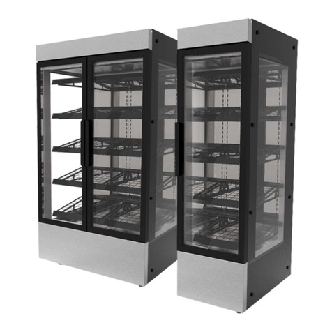
Victor Evolution SEHT60SW User manual

OPERATING MANUAL
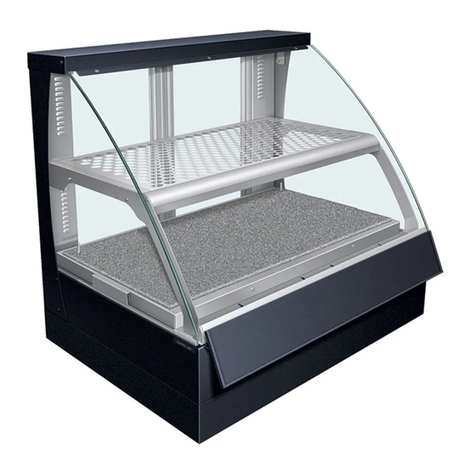
EVOLUTION HEATED RETAIL DISPLAY CABINET
MODEL NUMBERS
SEHT60SW • SEHT90SW
Caution: This manual must be read and understood before your appliance is installed, and operated.
CONTENTS
1. INTRODUCTION
2. USE AND BEST PERFORMANCE
2.1. SCOPE OF OPERATION
2.2. START-UP PROCEDURE
2.3. ADJUSTING THE UNIT TEMPERATURE (SET POINT)
3. CLEANING
3.1. CLEANING UNDER THE SHELF AND BASE COVERS
4. MAINTENANCE
4.1. REPLACING THE LIGHTS
5. WARRANTY
6. ENVIRONMENTAL CONDITIONS
7. SPECIFICATION
8. UNIT DIMENSIONS
9. SPARE PART ORDER CODES
10. INSTALLATION
10.1. UNPACKING AND ASSEMBLY
10.2. POSITIONING THE UNIT
11. DECLARATION OF CONFORMANCE
Please use the box provided below to record your model and serial number for future information, this can be found on the data label
on the appliance.
Model number:
Serial number:
1. INTRODUCTION
Thank you for buying a Victor product. Many years of satisfactory use from your purchase can be expected, if the operating, cleaning
and maintenance instructions are followed, however failure to do so may affect the warranty.
This manual contains instructions for the safe installation, operation and maintenance of the Victor product, model as stated on the
front cover. Check that the model number of your product as printed on the data label matches to one of the model numbers listed.
Instructions for unpacking and installing your new Victor product are located towards the rear of the manual (see section 10 -
INSTALLATION).

2. USE AND BEST PERFORMANCE
Caution Operator:
This appliance must only be operated by suitably trained or qualified persons aged 16 years and above who have read and
understood this manual. An operator is defined as the person who is responsible for switching the appliance on, adjusting
the temperature and its safe use.
Children shall not play with the appliance.
2.1. SCOPE OF OPERATION
This unit is only to be used to hold hot ready cooked products at a temperature to comply with the Food Hygiene Regulations.
This unit is not designed to heat up products from cold/ambient temperatures.
This unit has been designed to display ready prepared food for sale and to give the operator maximum control over the temperature
at which the food is held.
2.2. START-UP PROCEDURE
To obtain the best performance, follow the procedure below,
(a) Ensure the unit is connected to the power supply.
(b) The controls are located behind the lower front panel. Pull
the handle to swing the panel forward.
(c) Turn the unit on using the ‘Power’ Switch. This switches on
and off all power to the heating and lighting.
(d) All controllers will retain their previous temperature settings.
On first use this will be the factory setting (100ºC).
(e) The empty unit will take approximately 60 minutes to reach
set operating temperatures. Before placing any product on the
shelves, make sure the displays are showing the set operating
temperatures, or at a stable maximum (see below).
(f) It is possible that, given variations in environmental
conditions and the electrical power supply, the temperature
display will not achieve the set point. This does not indicate that the unit is faulty, only that the unit is running at full power.
(g) The temperature displays indicate the air temperatures coming from the vents at the front of the shelves not the product
temperature. The air temperatures where the product is displayed will be lower. The required setting to suit each customer’s product
can be found through experimentation.
(h) When loading, the product it should only be placed up to 50mm in from the left and right hand edges of the shelves, as there is
no heating in these areas.
(i) The operating temperature of each shelf, and the deck area, can be controlled individually by adjusting the appropriate controller,
see Section 2.3.
Note:
The unit is primarily designed to maintain an even product temperature across all shelves, by setting all shelves to the same set
point. Some variation in the product temperatures on different shelves can be achieved by altering the individual shelf set
points, but the temperature variation is limited.
2.3. ADJUSTING THE UNIT TEMPERATURE (SET POINT)
To adjust the operating temperature, follow the procedure below:
(a) Locate the controllers at the front of the unit (open the Front Panel) .
(b) Press and hold the left hand side button (i). The display will change to the set point
temperature.
(c) Keep the ibutton pressed Use the centre up down (^/v) buttons to select the
desired temperature between 65ºC and the unit maximum.
(d) Once the desired set point is reached, release all buttons and the display will revert to current temperature.
Figure 1 - Details of control panel
Figure 2 - Controller detail

3. CLEANING
Caution: child safety
Cleaning and user maintenance shall not be made by children.
Warning: do not jet wash or steam clean
This the appliance must not be cleaned with a jet wash or steam cleaner.
Warning: switch off and unplug
The unit must be switched off and unplugged from the electrical supply before cleaning.
Stainless steel surfaces will give you many years of trouble-free use as long as you follow a few simple rules. If it appears to mark do
not worry, it is usually not the steel but something deposited on it which has stained.
Wash all surfaces before use:
You should use a damp cloth and a mild detergent or soap, or similar cleaner. Wipe over with a cloth, rinsed well with clean water, to
remove any residue and dry the surfaces with a soft cloth. Clean regularly when in use. Do use soft cloths, nylon or bristle brushes.
Do not use:
Metal scrapers, wire brushes or wire wool pads as they can scratch the steel. Do take care when handling sharp objects as they can
scratch the surface of the stainless steel. Any scratches on stainless steel will blend together over a period of time and become less
noticeable with age. There is no detriment to the corrosion resistance or general performance of the material.
Do not use:
Bleach for cleaning purposes (remember dishwasher powders, sterilising agents and similar products all contain chlorides). If used,
black pit marks, large brown patches or other such effects may appear and permanent damage may be caused. If used inadvertently
rinse immediately with clean water.
Do not splash the unit with bleach when cleaning around the counter:
If you do, rinse the surface immediately with clean water thoroughly.
Do not allow:
Corrosive foodstuffs such as fruit juices, vinegar, mustards, pickles, mayonnaise, etc., to remain on stainless steel for long periods.
Wash and rinse away.
Do not leave:
Steel objects or utensils standing on the stainless steel surfaces for long periods. They can rust and leave marks. After cleaning with
detergent always remove residues with a wet cloth and wipe dry, if left they can have an etching effect on the surface.
Correctly applied the above instructions will result in continuous good looks!
3.1. CLEANING UNDER THE SHELF AND BASE COVERS
Do not do this until the unit has been unplugged and
allowed to cool.
The covers over the shelves and base heating area are designed
to be removable for cleaning.
Removing the Shelf and Base Covers
(a) Each Cover plate can be removed for cleaning and allow
access to clear around the elements.
(b) Please note the covers are not interchangeable and have to
be returned to their original positions.
(c) Carefully lift each Cover panel from the unit and store safely.
Remove the Right hand (from the customer viewpoint) cover
first.
(d) In the event of a spillage the Front Vents can be removed to
allow full access (see below).
(e) Replace once cleaning is complete, ensuring the covers are
returned to their original positions.
Removing the Front Vent
(a) Once the Shelf covers have been removed, lift the Support
Bar up and remove.
(b) Pull the Front Vent assembly towards the back of the unit
and lift clear.
(c) There is now full access to the inside of the shelf to clean as
required.
(d) Once Cleaning is complete, replace the Front Vent by
locating the Tabs at each end into the slots and pushing firmly
forward.
(e) Replace the Support Bar into the Slots at the front and back
of the shelf/base assembly.
Figure 3 - Remove shelf covers
Figure 4 - Front lip removal
4. MAINTENANCE
Trained Person
Maintenance shall be carried out by a trained competent person who is wearing the appropriate PPE (personal protect equipment).
Caution: Child Safety
Cleaning and user maintenance shall not be made by children.
Warning: switch off and unplug
The unit must be switched off and unplugged from the electrical supply before cleaning.
4.1. REPLACING THE LIGHTS
The unit is fitted with LED array strip lighting. The LED array is replaceable
(a) Turn off the power to the unit, and unplug from the supply.
(b) Unclip the LED strip from the brackets.
(c) The LED strip can be made of several pieces, chained together.
(d) Unplug the lead and/or adjacent LED light strips.
(e) Replace the faulty strip.
(f) Reverse the process to fit the new strip.
Yearly Safety Check
You should have your appliance inspected and tested for electrical safety at least once a year as required by the Electricity at Work
Regulations.
Electrical Mains Lead
If the supply cord is damaged, it must be replaced by the manufacturer, its service agent or similarly qualified persons in order to
avoid a hazard. Do not use if the supply cord is damaged.
5. WARRANTY
As a manufacturer of catering equipment, Victor Manufacturing Ltd offers warranty on all
goods manufactured by the company and supplied by its United Kingdom Distributors.
Victor Manufacturing Ltd is renowned for its reliability and Victor Manufacturing Ltd
provides on-site warranty in case of failure included in the purchase price, which covers
the costs of spare parts and labour on your Victor Manufacturing Ltd goods from the date
of invoice for a period of 24 months.
The Victor Manufacturing Ltd warranty does not affect any legal rights you have against the person who supplied your Victor
Manufacturing Ltd goods or any other legal right against Victor Manufacturing Ltd under the laws of the United Kingdom - it is an
addition to those rights.
All goods sold by Victor Manufacturing Ltd are subject to the Company’s standard conditions of sale, a copy of which is available
upon request.
Where the goods and components supplied by Victor Manufacturing Ltd are of the company’s design and manufacture, Victor
Manufacturing Ltd will make good any defects in those goods provided Victor Manufacturing Ltd liability will be limited to the
following:
It is the purchaser’s responsibility to prove that the unit is under warranty, e.g. receipt of purchase, invoice number, serial
number, etc.
Damaged in transit claims must be reported in writing to the company within 3 days of receipt for your claim to be validated.
Damaged goods will not be replaced or repaired if they have been used.
Victor Manufacturing Ltd must authorise all warranty repairs prior to the commencement of work. Work carried out on goods
prior to authorisation will not be covered nor will any resultant damage.
All warranty will be immediately invalidated if in the reasonable opinion of Victor Manufacturing Ltd, unauthorised repairs or
modifications have been made to the goods, in the case of accident, misuse, or damage caused by improper installation and
altered or missing serial numbers. Victor Manufacturing Ltd will not provide warranty repairs if in our opinion the problem
resulted from externally caused damage, use outside the goods specification, faults caused by inexperienced or non-approved
repairers. All warranty will be immediately invalidated if installation of equipment is not in accordance with Victor Manufacturing
Ltd installation instructions supplied.
Customer adjustments explained in the operating manual are not covered by Victor Manufacturing Ltd on-site warranty.
Assistance can be received by contacting the warranty desk.
Figure 5 - LED lamp removal

The liability of Victor Manufacturing Ltd and its appointed engineers are limited to the cost of repairs (parts and labour only) of
the unit under warranty. Loss of food or other damages caused by faulty goods are not covered by the warranty.
No fault found warranty calls and installation errors are not covered under Victor Manufacturing Ltd warranty and will result in a
charge being made for the call-out and on-site labour for our appointed engineer. The Victor Manufacturing Ltd warranty does
not cover the replacement of used consumables, or parts that require period adjustment or lubrication, unless the part is faulty.
You must have evidence that routine maintenance has been carried out by a qualified engineer in accordance with the
instruction manual. This is of particular importance with refrigerated and gas fuelled appliances. Work made necessary by lack
of routine maintenance or cleaning is not covered by this warranty and will be chargeable.
Victor Manufacturing Ltd parts and labour warranty is valid for the United Kingdom Mainland only. (Parts only all areas outside
the United Kingdom Mainland.)
Some parts are automatically not covered by the Victor Manufacturing Ltd warranty (e.g. panels, glass, lamps, shelves, etc.)
Many surface finishes including paint and plastic coated steel can be scratched and damaged if not properly cared for; such
damage is not covered by the Victor Manufacturing Ltd warranty.
6. ENVIRONMENTAL CONDITIONS
This appliance contains electrical components and should be used and stored indoors only under the conditions listed in the table
below.
Environmental
Temperature (Storage) -5°C - 35°C
Relative Humidity (Storage) Max. 80% up to 31°C decreasing linearly to 50% at 40°C
Temperature (Operation) 16°C to 25°C
Relative Humidity (Operation) 60% Max (at 25°C)
Altitude Not exceeding 2000m
Electrical Supply Fluctuation 230V AC +10%, - 6%
7. SPECIFICATION
This appliance contains electrical components and should be used and stored indoors only under the conditions listed in the table
below.
The Model Number
Model Code Model size Type code Rear/Door type
4 letter model code 2 or 3 digit size code 1 or 2 letter type code 1 or 2 letter type code
Model Code: Model Size: Type Code: Rear/Door Code:
SEHT - Square glass, 60 - 600mm width S- Self Service (Open front) W- Wall Style (Controls to front)
Evolution, Heated, Tall 90 - 900mm width
Appliance Electrical Connection and Fuse Specification
Model: Fuse/Protection Supply/Plug
Method Location Type
SEHT60... Fuse Plug 13A (BS1362) 13A (3 pin)
SEHT90... MCB Control Panel 16A (Type B) 16A (Commando)
Appliance Specification
Model: Unit Weight Max Load Max Load Supply Voltage Max Current Max Power
(Unloaded) (Base) (Each shelf) (Vac)
SEHT60SW 195Kg 20Kg 12Kg 220-240/50Hz 12.5A* 3kW
SEHT90SW 240Kg 20Kg 12Kg 220-240/50Hz 15.5A* 3.8kW
*Max power and current at upper supply voltage 240V.

8. UNIT DIMENSIONS
Unit Dimensions
Unit Overall Width Overall Depth Overall Height
SEHT60... 609 750 1948
SEHT90... 909 750 1948
Figure 6 - Unit dimensions

9. SPARE PART ORDER CODES
When ordering any spare parts from your distributor always quote the model and serial number. This can be found on the data label
affixed close to the mains lead connection point to your product. It is also advisable to make a note of these numbers in the space
provided on the front cover of this manual.
The most common spare parts and their order codes are listed in the following tables. If you are unsure of your Victor product model
number check your data label and Section 8 of this manual.
Spares order codes 600mm wide units
SEHT60SW SEHT90SW
Heating Element 22-0393 22-0394
Rocker Switch (Red) 24-0040 24-0040
Controller (Inc. Probes) 60-2000 60-2000
MCB (16A) n/a 25-0054
LED Light Bar (260mm) n/a 26-0159
LED Light Bar (448mm) 26-0142 26-0142
LED Interconnecting Lead 26-0175 26-0175
LED driver 26-0171 26-0172
Castor Swivel 52-0232 52-0232
Castor Swivel (Brake) 52-0233 52-0233
Side Glass (Left hand) 65-2420 65-2420
Side Glass (Right hand) 65-2421 65-2421
Front Riser Glass 65-2422 65-2427
Ticket Strip (1 per shelf ) 53-0483 53-0481
Fan - Hot Air Circulation 60-1002 60-1002
Fan - Control Box cooling 60-1030 60-1030
Shelf (x3)
Shelf Dole Plate (Left Hand) PLA0149 PLA0379
Shelf Dole Plate (Right Hand) PLA0150 PLA0380
Base)
Base Dole Plate (Left Hand) PLA0356 PLA0381
Base Dole Plate (Right Hand) PLA0357 PLA0382
Mains supply Cable 23-0150 (inc Plug) 23-0088 (3.5m)
Mains Supply Plug 23-0150 (inc Cable) 25-0036
Wire Trays (each)
Table 3 Spare part codes SEH120/150
10. INSTALLATION
10.1 UNPACKING AND ASSEMBLY
All protective coating used on stainless steel surfaces of the unit must be removed. The exposed surfaces can then be wiped clean
with a damp cloth, using a mild detergent or soap if necessary.
Do not use any abrasive material or form of bleach for cleaning purposes. Please see cleaning section of this manual.
10.2. POSITIONING THE UNIT
• Ensure the area is clean, level and clear of obstructions.
• When moving the unit, push on the metal base, not the glass.
• Move the unit into the required position.
• Ensure all points below with regards to siting have been considered.

• Four castors are fitted to allow the unit to be easily moved to where it is to be used.
• Two of the castors can be locked so the unit remains static whilst in use.
• Locking castors must be locked before the unit is plugged into the electrical power supply.
Warning: Fire prevention
Where this appliance is to be positioned in close proximity to a wall, partition, kitchen furniture, decorative finishes, etc., it is
recommended that they be made of a non-combustible material or clad in a suitable non-combustible heat insulating material and
that the closest attention be paid to fire preventative regulations.
Combustible materials must not be stored on and/or around this appliance.
Warning: Hot Surfaces
During operation the metal and glass parts of this appliance will get hot, this must be taken into consideration when positioning this
appliance.
Warning: Electrical supply voltage
The 600 wide appliance is fitted with a 13 Amp fused plug and require connection to a 13 Amp socket outlet only.
The 900 wide appliances are fitted with a 16 Amp plug and require connection to a 16 Amp socket outlet only.
These models are suitable for 220 - 240V A.C. 50Hz supply only. Ensure that the electricity supply is as stated on the model’s data
plate.
Warning: Electrical earthing
This unit must be earthed, do not touch internal wiring.
Wires in the mains lead are coloured in accordance with the following code:
Green and Yellow - Earth (E)
Blue - Neutral (N)
Brown - Live (L)
7. IF YOUR EQUIPMENT FAILS
Refer to the instruction manual. If the problem still cannot be resolved, prepare a description of the fault you have.
Make sure you have your proof of purchase document (Invoice number or serial number) and the model number of the equipment
that has failed.
Contact the warranty department on the following numbers:
• Warranty Desk Tel No: 01274 722125 (Office hours)
• Warranty Desk Fax No: 01274 307082 (Office hours)
• Emergency Warranty Tel No: 07876 898114 (All other times)
Warranty repairs are carried out between
9.00am and 5.00pm Monday - Friday.
Access required outside normal working hours may incur charges.
Registered Office:
Victor Manufacturing Ltd
Prospect Works, Off South Street, Keighley BD21 5AA
Tel: 01274 722125
Email: [email protected].uk

In accordance with BS EN ISO 17050 -1:2010
We of
Victor Manufacturing Limited
Prospect Works, Off South Street, Keighley BD21 5AA
in accordance with the following Directive(s):
2006/42/EC: Machinery Directive (MD)
2014/30/EU: Electromagnetic Compatibility Directive (EMC)
2011/65/EU: Restriction of the use of certain Hazardous Substances (RoHS)
hereby declare under our sole responsibility that:
Appliance(s): Evolution Heated Retail Display
Model number(s): SEH60ED1 • SEH60SW • SEH60SPD1 • SEH90ED1/2 • SEH90SW • SEH90SPD1/2
SEH120ED2 • SEH120SW • SEH120SPD2 • SEH150ED2 • SEHT60SW
is/are in conformity with the applicable requirements of the following documents
Ref. No. Title Edition/date
BS EN 60335-1 Household and similar electrical appliances 2012 +A11:2014
Safety - Part 1: General requirements
BS EN 60335-2-49 Part 2-49: Particular requirements for commercial electric 2003 +A11:2012
appliances for keeping food and crockery warm
BS EN 60335-2-50 Part 2-50: Particular requirements for commercial electric 2003 +A1:2008
bains marie
BS EN 61000-6-1 Electromagnetic compatibility (EMC). Generic standards. 2007
Immunity for residential, commercial and light-industrial
environments
BS EN 61000-6-3 Electromagnetic compatibility (EMC). Generic standards. 2007 +A1:2011
Emission standard for residential, commercial and
light-industrial environments
I hereby declare that the equipment named above has been designed to comply with the relevant sections
of the above referenced specifications and is in accordance with the applicable Essential Requirements of
the Directives.
The Technical Documentation for the above named machinery is available from Victor Manufacturing Ltd at
the above address.
Signed:
Name:
Position:
Location
On:
VDT-0004(1) - EC Declaration of Conformity Pro-forma - Electrically Heated products under MD
EC DECLARATION OF CONFORMITY
Certificate No.
VDC-0013(4)
12. EC DECLARATION OF CONFORMITY
This manual suits for next models
1
Table of contents
Other Victor Display Case manuals