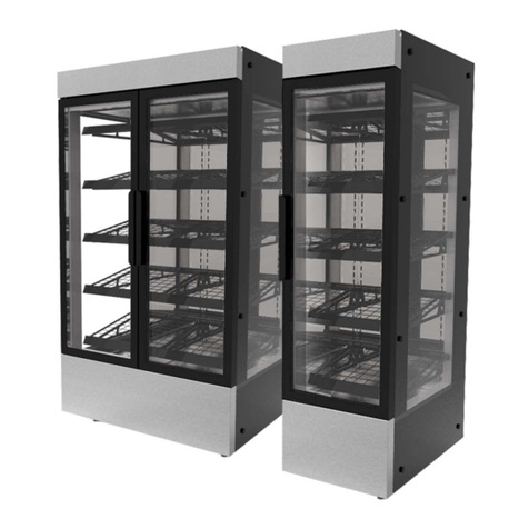
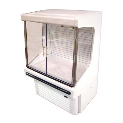
Victor Evolution SER90SW-EURO User manual

OPERATING MANUAL
EVOLUTION REFRIGERATED RETAIL DISPLAY CABINET - EUROPEAN SPEC
MODEL NUMBER
SER90SW-EURO
Caution: This manual must be read and understood before your appliance is installed, and operated.
CONTENTS
1. INTRODUCTION
2. USE AND BEST PERFORMANCE
2.1. SCOPE OF OPERATION
2.2. START UP PROCEDURE - WALL STYLE MODELS (SER**SW)
2.3. PULLING DOWN TO TEMPERATURE
2.4. LOADING THE CABINET
2.5. ADJUSTING THE UNIT TEMPERATURE (SET POINT)
2.6. DEFROSTING
2.7. SHELF POSITION AND ANGLE ADJUSTMENT
3. CLEANING
4. MAINTENANCE
4.1. CLEANING THE CONDENSER
4.2. CONDENSER CLEANING METHOD
4.3. CLEANING THE CONDENSER
4.4. CLEANING THE BOTTOM OF THE CABINET AND THE EVAPORATOR
4.5. REPLACING THE LIGHTS
5. WARRANTY
6. ENVIRONMENTAL CONDITIONS
7. SPECIFICATION
8. UNIT DIMENSIONS
9. SPARE PART ORDER CODES
10. INSTALLATION
10.1. UNPACKING AND ASSEMBLY
10.2. POSITIONING THE UNIT
10.3. INSTALLATION OF SER**SW (WALL STYLE) UNITS
10.4. INSTALLATION INTO A COUNTER
10.5. INSTALLATION OF FRONT VENTED UNITS INTO A COUNTER
11. DECLARATION OF CONFORMANCE
Please use the box provided below to record your model and serial number for future information, this can be found on the data label
on the appliance.
Model number:
Serial number:

1. INTRODUCTION
Thank you for buying a Victor product. Many years of satisfactory use from your purchase can be expected, if the operating, cleaning
and maintenance instructions are followed, however failure to do so may affect the warranty.
This manual is for the safe installation, operation and maintenance of the Victor product model as stated on the front cover. Check
that the model number of your product as printed on the data label matches to one of the model numbers listed.
2. USE AND BEST PERFORMANCE
Caution Operator:
This appliance must only be operated by suitably trained or qualified persons aged 16 years and above who have read and
understood this manual. An operator is defined as the person who is responsible for switching the appliance on, adjusting
the temperature and its safe use.
Children shall not play with the appliance.
2.1. SCOPE OF OPERATION
Please remember the refrigeration system is not designed to chill food, but is designed to maintain it at a satisfactory temperature
before serving.
Operation:
Evolution display cabinets are designed to maintain food at a satisfactory temperature before serving, it is not designed to chill food.
All food placed in the cabinet must be pre-chilled to between 1°C & 7°C.
Classification:
Models: SER**SW - At a set point temperature of around 2°C, the display cabinet will meet the performance classification of BS ISO
23953-2: - Climate Class 3 - M package classification M2 (an ambient of 25°C with RH 60%, food temperature control -1°C to 7°C)
Note: The display shows the air temperature within the cabinet, not the food temperature.
2.2 START UP PROCEDURE - WALL STYLE MODELS (SER**SW)
The controls are located on the front (customer side) of the unit, in the back of the
display area.
All day to day power and control functions are dealt with by the controller.
Turn on the power Switch
(a) Locate the power switch on the rear of the unit.
(b) Switch to the unit on (the switch will be illuminated.
(c) For Day-to-day operation the unit can be switched on and off using the controller.
Turning the Lights On/Off
(a) To switch on the lights press button (3).
(b) To switch off the lights press button (3) again.
Turning the Refrigeration On/Off
(a) Press and hold the right hand button (4), this will switch the unit on. The display will
now read the unit temperature and will start to run after one minute.
(b) Press and hold the right hand button (4), this will switch the unit off. The display will
now read off.
2.3. PULLING DOWN TO TEMPERATURE
Getting to Temperature
Once the refrigeration has been turned on the unit will start to cool the air inside the
unit down to the required temperature (determined by the set point).
The air temperature in the unit is displayed on the controller screen.
Depending on the ambient temperature, allow the cabinet approximately 30 minutes to cool to the required temperature before
loading.
2.4. LOADING THE CABINET
Load the Cabinet Base and shelves as required.
Caution: Be careful not to over pack the cabinet and restrict the airflow between the front and rear vents, as this will affect the
efficiency and performance of the refrigeration system.
The Base and Shelf panels must be loaded evenly across the width. See section 7, Appliance Specification Table, for maximum Base
and shelf loadings. Exceeding these loadings, or loading the shelves unevenly will result in damage to the unit.
Warning: The cabinet must not be moved when loaded.
Figure 1 - Position of power switch
Figure 2 - Diagram showing the Wall style
model controls

2.5. ADJUSTING THE UNIT TEMPERATURE (SET POINT)
The refrigeration system is controlled by a digital temperature controller, it is factory set to 2°C, but can be adjusted between 0 & 8°C.
Displaying the Set Point.
(a) The current temperature set point is displayed by pressing and holding the left hand button (1).
Adjusting the Set Point
(a) Press and hold the left hand button (1), then press the (middle) up and down arrow buttons, (2) & (3) to adjust the temperature
up and down.
(b) Once the desired set point value is displayed on the controller, release the left hand button (1).
2.6. DEFROSTING
• All refrigeration systems frost up when operating.
• This unit is programmed to defrost periodically.
• No manual defrost is required.
• The refrigeration system will automatically defrost every 2 hours for approximately 20 minutes.
• The controller will display ‘def’ during the defrost cycle.
• Water collected from the defrost operation is evaporated off within the appliance.
2.7. SHELF POSITION AND ANGLE ADJUSTMENT
The position and angle of the glass shelves can be adjusted to suit the customers’
requirements. The possible positions of each glass shelf are restricted by the wiring to
the shelf lighting. The glass shelves may be removed for cleaning.
Removing the Glass Shelves
(a) Carefully lift each glass panel from the unit and store safely.
(b) When replacing the doors ensure the‘Groove’handle side is on the outside.
Adjusting the Shelf Positions
(a) Remove the glass shelves and the Rear Shelf cross member (fitted loose).
(b) Shelf Bracket positons can be now altered.
(c) Lift the shelf brackets from the slots in the rear uprights and move to the new
required position.
(d) The angle of the shelf can be adjusted by using one of the two slots in the shelf bracket mounting (see Figure 3).
(e) Check the brackets are level side to side and at the same angle.
(f) Replace the Rear Shelf cross member and the glass shelves.
3. CLEANING
Caution: child safety
Cleaning and user maintenance shall not be made by children.
Warning: do not jet wash or steam clean
This the appliance must not be cleaned with a jet wash or steam cleaner.
Warning: switch off and unplug
The unit must be switched off and unplugged from the electrical supply before cleaning.
Stainless steel surfaces will give you many years of trouble-free use as long as you follow a few simple rules. If it appears to mark do
not worry, it is usually not the steel but something deposited on it which has stained.
Wash all surfaces before use:
You should use a damp cloth and a mild detergent or soap, or similar cleaner. Wipe over with a cloth, rinsed well with clean water, to
remove any residue and dry the surfaces with a soft cloth. Clean regularly when in use. Do use soft cloths, nylon or bristle brushes.
Do not use:
Metal scrapers, wire brushes or wire wool pads as they can scratch the steel. Do take care when handling sharp objects as they can
scratch the surface of the stainless steel. Any scratches on stainless steel will blend together over a period of time and become less
noticeable with age. There is no detriment to the corrosion resistance or general performance of the material.
Do not use:
Bleach for cleaning purposes (remember dishwasher powders, sterilising agents and similar products all contain chlorides). If used,
black pit marks, large brown patches or other such effects may appear and permanent damage may be caused. If used inadvertently
rinse immediately with clean water.
Figure 3 - Diagram showing the Shelf brackets
angle adjustments

Do not splash the unit with bleach when cleaning around the counter:
If you do, rinse the surface immediately with clean water thoroughly.
Do not allow:
Corrosive foodstuffs such as fruit juices, vinegar, mustards, pickles, mayonnaise, etc., to remain on stainless steel for long periods.
Wash and rinse away.
Do not leave:
Steel objects or utensils standing on the stainless steel surfaces for long periods. They can rust and leave marks. After cleaning with
detergent always remove residues with a wet cloth and wipe dry, if left they can have an etching effect on the surface.
Correctly applied the above instructions will result in continuous good looks!
4. MAINTENANCE
Trained person
Maintenance shall be carried out by a trained competent person who is wearing the appropriate PPE (personal protect equipment).
Caution: Child safety
Cleaning and user maintenance shall not be made by children.
Warning: switch off and unplug
You must switch off and disconnect the appliance from the electrical mains supply before carrying out maintenance or removing any
covers or components which have been fastened using screws.
4.1. CLEANING THE CONDENSER
The refrigeration system will pick up dust from the air, which will build up on the fins of the condenser. This will cause the condenser
to lose effectiveness over time.
It is important to examine, and clean, the condenser as necessary, or every 3 months. The condenser is made up of closely packed
metal fins that might present a cut hazard, the use of strong industrial protective gloves is recommended.
Note: The frequency of checking, and cleaning, the condenser varies between installations and depends on the positioning of the unit,
the amount of time the unit is run during a day and the number of people walking past in front of the unit.
In installations where the units are on for 24 hours a day and have a high volume of people passing in front of the unit this cleaning
may be required once a week. It is, therefore, advisable to check weekly when first installed to determine the appropriate cleaning
frequency. The position and method of accessing the Condenser will vary depending on the unit size.
4.2. CONDENSER CLEANING METHOD
(a) To clean the condenser, use a brush attachment on a vacuum cleaner.
(b) Care must be taken not to damage the condenser fins, the dust needs to be
removed gently.
(c) Do not use force or stabbing motions with the brush.
4.3. CLEANING THE CONDENSER
(a) The Condenser is located on the front (customer facing) side of the unit.
See Figure 4.
(b) Remove the Condenser Access Panel, by simply pulling it forward until free. Take
care not to damage the vents.
(c) Once the panel is unclipped, lift clear, and store safely.
(d) Clean the condenser using the cleaning method in Section 4.2.
(e) Once cleaning is complete, replace the cover by aligning the Condenser Access
Panel with the aperture and pressing firmly.
Warning: Failure to clean the condenser regularly will result in the refrigerant in the appliance not being cooled. The refrigerant will over
heat and activate the high pressure cut out switch, turning the refrigeration system off. The cut out is self-resetting, but it will repeatedly
activate if the condenser is not cleaned. If the appliance appears to be working, but is not cooling correctly, check the condenser.
Damage caused by poor maintenance and cleaning of the condenser is not covered by your Victor warranty, see Section 5 (Warranty).
Call out of an engineer under warranty that proves to be a blocked condenser due to poor cleaning will be charged for.
Figure 4 - Condenser cleaning - Front Vent
4.4. CLEANING THE BOTTOM OF THE CABINET AND THE EVAPORATOR
The panels at the bottom of the cabinet can be removed for
cleaning. This also allows access to the evaporator coil for
cleaning.
Removing the Cabinet Base
(a) Lift out the Return Grille.
(b) Lift out the Base Panel.
Cleaning the Evaporator
(a) Ensure the unit is turned off and isolated before attempting
to clean the
(b) Evaporator.
(c) Remove the Base panels - see Figure 5.
(d) Remove the two screws securing the Fan Baffle panel.
(e) Tilt the Fan Baffle forward until it rests against the front of the base.
(f) Remove the Shelves and the Back Panel
(g) Lift the Evaporator Cover clear of the baffle.
(h) There is now clear access to be Evaporator for cleaning etc.
(i) Reverse the above process to replace the panels – Ensure all cables are not trapped when returning the Evaporator Cover and Fan
Baffle.
4.5 REPLACING THE LIGHTS
The unit is fitted with LED array strip lighting. The LED array is replaceable. See Figure 6.
(a) Turn off power to the unit.
(b) Unclip the LED strip from the brackets.
(c) The LED strip can be made of several pieces, chained together.
(d) Unplug the lead and/or adjacent LED lights.
(e) Replace the faulty strip.
(f) Reverse the process to fit the new strip.
Yearly Safety Check
You should have your appliance inspected and tested for electrical safety at least once a
year as required by the Electricity at Work Regulations.
Electrical Mains Lead
If the supply cord is damaged, it must be replaced by the manufacturer, its service agent or similarly qualified persons in order to avoid a
hazard. Do not use if the supply cord is damaged.
5. WARRANTY
As a manufacturer of catering equipment, Victor Manufacturing Ltd offers warranty on all goods manufactured by the company and
supplied by its United Kingdom Distributors.
Victor Manufacturing Ltd is renowned for its reliability and Victor Manufacturing Ltd provides on-site warranty in case of failure
included in the purchase price, which covers the costs of spare parts and labour on your Victor Manufacturing Ltd goods from the
date of invoice for a period of 24 months.
The Victor Manufacturing Ltd warranty does not affect any legal rights you have against the person who supplied your Victor
Manufacturing Ltd goods or any other legal right against Victor Manufacturing Ltd under the laws of the United Kingdom - it is an
addition to those rights.
All goods sold by Victor Manufacturing Ltd are subject to the Company’s standard conditions of sale, a copy of which is available
upon request.
Where the goods and components supplied by Victor Manufacturing Ltd are of the company’s design and manufacture, Victor
Manufacturing Ltd will make good any defects in those goods provided Victor Manufacturing Ltd liability will be limited to the
following:
It is the purchaser’s responsibility to prove that the unit is under warranty, e.g. receipt of purchase, invoice number, serial
number, etc.
Damaged in transit claims must be reported in writing to the company within 3 days of receipt for your claim to be validated.
Figure 5 - Diagram showing access to the Evaporator
Figure 6 - LED Lamp removal

Damaged goods will not be replaced or repaired if they have been used.
Victor Manufacturing Ltd must authorise all warranty repairs prior to the commencement of work. Work carried out on goods
prior to authorisation will not be covered nor will any resultant damage.
All warranty will be immediately invalidated if in the reasonable opinion of Victor Manufacturing Ltd, unauthorised repairs or
modifications have been made to the goods, in the case of accident, misuse, or damage caused by improper installation and
altered or missing serial numbers. Victor Manufacturing Ltd will not provide warranty repairs if in our opinion the problem
resulted from externally caused damage, use outside the goods specification, faults caused by inexperienced or non-approved
repairers. All warranty will be immediately invalidated if installation of equipment is not in accordance with Victor Manufacturing
Ltd installation instructions supplied.
Customer adjustments explained in the operating manual are not covered by Victor Manufacturing Ltd on-site warranty.
Assistance can be received by contacting the warranty desk.
The liability of Victor Manufacturing Ltd and its appointed engineers are limited to the cost of repairs (parts and labour only) of
the unit under warranty. Loss of food or other damages caused by faulty goods are not covered by the warranty.
No fault found warranty calls and installation errors are not covered under Victor Manufacturing Ltd warranty and will result in a
charge being made for the call-out and on-site labour for our appointed engineer. The Victor Manufacturing Ltd warranty does
not cover the replacement of used consumables, or parts that require period adjustment or lubrication, unless the part is faulty.
You must have evidence that routine maintenance has been carried out by a qualified engineer in accordance with the
instruction manual. This is of particular importance with refrigerated and gas fuelled appliances. Work made necessary by lack
of routine maintenance or cleaning is not covered by this warranty and will be chargeable.
Victor Manufacturing Ltd parts and labour warranty is valid for the United Kingdom Mainland only. (Parts only all areas outside
the United Kingdom Mainland.)
Some parts are automatically not covered by the Victor Manufacturing Ltd warranty (e.g. panels, glass, lamps, shelves, etc.)
Many surface finishes including paint and plastic coated steel can be scratched and damaged if not properly cared for; such
damage is not covered by the Victor Manufacturing Ltd warranty.
6. ENVIRONMENTAL CONDITIONS
This appliance contains electrical components and should be used and stored indoors only under the conditions listed in the table
below.
Environmental
Temperature 5°C - 35°C
Relative Humidity Max. 80% up to 31°C decreasing linearly to 50% at 40°C
Altitude Not exceeding 2000m
Electrical Supply Fluctuation Voltage fluctuation not exceeding 10%
7. SPECIFICATION
This appliance contains electrical components and should be used and stored indoors only under the conditions listed in the table
below.
The Model Number
Model Code Model size Type code
3 letter model code 2 or 3 digit size code 1 or 2 letter type code
Model Code: Model Size: Type Code: Reference
SER - Square glass, 60 - 600mm width SW - Open Front EURO -
Evolution, Refrigerated. 90 - 900mm width Closed back wall model European power
120 - 1200mm width connection specification
Appliance Fuse Specification
Fuse Plug 13A Schuko
Internal fuses F1 /2 16A (Type 10 x 38mm - iec60269-2)
F3 /4 2A (Thermal circuit breaker)

Appliance Specification
Model: Unit Weight Max Load Max Load Supply Voltage Max Current (A)
(Unloaded) (Base) (Each shelf) (Vac)
SER90SW-EURO 195Kg 20Kg 12Kg 220-240/50Hz 8.5
Note: The Refrigerated Display Cabinet can be supplied to run on a 60Hz supply. If the cabinet is a 60Hz version it is specified on the
data labels.
Refrigeration System Specification
Model: Refrigerant Refrigerant Max allowable Pressure switch
Charge (g) Pressure (PS) (bar) activation (bar)
(PS) Low (PS) High
SER90SW-EURO R452a/R404a 900 24.8 24.8 27.6 +/- 1.0
Check the Data label to confirm the refrigerant type and charge.
Note: Any pressure strength testing/tightness testing must be carried out in accordance with BSEN 378-2.
8. UNIT DIMENSIONS
Unit Dimensions
Unit Overall Overall Overall Rear Front Side Body Counter Deck Vent Vent Vent
Width Depth Height Column O/hang O/hang Width Top T/ness Opening Opening Height
Width Height Width Height
W D H RCW FO SO BW CTH DT VOW VOH VH
SER90SW
900 750 1350 140 22 24 852 556 48 513 235 236
Note - SER..SW (wall style units) must be positioned 150mm from the rear wall, and are fitted with a spacer to ensure the gap is
maintained.
Figure 7 - Unit dimensions

9. SPARE PART ORDER CODES
When ordering any spare parts from your distributor always quote the model and serial number. This can be found on the data label
affixed close to the mains lead connection point to your product. It is also advisable to make a note of these numbers in the space
provided on the front cover of this manual.
The most common spare parts and their order codes are listed in the following tables. If you are unsure of your Victor product model
number check your data label and Section 8 of this manual.
Spares order codes
SER90SW-EURO
Compressor (50Hz) 72 - 0264
Condenser Unit 72 - 0901
High Pressure Cut out 24 - 0180
Dryer 60 - 0181
Access fittings 61 - 0211
Evaporator Coil 61 - 0535
Evaporator Fan 62 - 0181
LED Light (260mm) 26 - 0159
LED Light (448mm) 26 - 0142
LED driver 26 - 0171
LED lamp Connecting Cable 26 - 0163
Glass shelf - Lower (per part) 77 - 1249
Glass shelf - Top (per part) 77 - 1127
Shelf bracket - Lower LH SHB0230
Shelf bracket - Lower RH SHB0231
Shelf bracket - Top LH SHF0228
Shelf bracket - Top RH SHF0229
Switch Green 62 - 0122
Digital Controller 60 - 0229
Controller Keypad 60 - 0330
Boil-off tray element 22 - 0308
Fuse F1/F2 (16A) 28 - 0042
Fuse F3/4 (2A) 24 - 0090
Fuse Holder (10x38) 28 - 0047
H.P.C Relay 24 - 0297
Mains Lead (3.5M) 23 - 0085
Plug (Schuko) 25 - 0115
Casters swivel (Brake) 52 - 0250
Casters swivel 52 - 0240
Canopy Glass - Double Glazed 65 - 2001
End Glass (LH) - Double Glazed 65 - 2220
End Glass (RH) - Double Glazed 65 - 2221
Lower Riser (Single Glazed) 65 - 2185
Upper Riser (Single Glazed) 65 - 2249
Glass Trim (Painted) 77 - 9001
Table 1. Spare part codes

10. INSTALLATION
10.1 UNPACKING AND ASSEMBLY
All protective coating used on stainless steel surfaces of the unit must be removed. The exposed surfaces can then be wiped clean
with a damp cloth, using a mild detergent or soap if necessary, as detailed in Section 3 Cleaning.
Do not use any abrasive material or form of bleach for cleaning purposes.
10.2. POSITIONING THE UNIT
• Ensure the area is clean, level and clear of obstructions.
• When moving the unit, push on the metal base, not the glass.
• Move the unit into the required position.
• Four castors are fitted to allow the unit to be easily moved to where it is to be used.
• Two of the castors can be locked so the unit remains static whilst in use.
• Locking castors must be locked before the unit is plugged into the electrical power supply.
Ensure all points below with regards minimum rear clearance distances and siting have been considered.
10.3. INSTALLATION OF SER**SW (WALL STYLE) UNITS
These units are designed to be positioned against a wall and only accessed from the
customer side.
SER**SW wall style unit’s minimum rear distance: A minimum rear clearance of 150mm
behind the unit and the wall is required provided that there is good ventilation and no
excessive heat build-up (ambient temperatures need to remain below 25°C). There
must be some means of the air off from the back of the unit to escape either to the
side or over the top of the unit. Failure to do this will result in poor perforce of the unit
and possible damage as the refrigeration system cannot work correctly and may cause
it to trip out on the high pressure safety switch.
Wall style units are supplied with a 150mm deep spacer to ensure the correct
minimum gap is maintained at the rear of the unit to ensure the safe and efficient
operation of the refrigeration system.
Removing these spacers, or blocking this clearance will result in the refrigeration
system failing.
Warning: Position away from heat sources - Do not site the appliance in the immediate
vicinity of a heat source,
Do not site the appliance where warm/hot air can be drawn
into the cool air inlet of the appliance, failure to ensure a good
supply of coolant air below 25°C can result in the refrigeration
system over heating and cutting out. This appliance is fitted
with a refrigerant pressure cut-out that will activate and switch
the appliance off when the refrigeration system inside cannot
cool correctly.
Caution: Air vents
Do not position the appliance so as to obstruct the air vents on
either the operator or customer sides, or the vents in the plinth,
of the appliance (as applicable). Do not place anything in front
of the air vents as to obstruct them. Adequate airflows are vital
to the correct functioning of the refrigeration system.
Caution: Strong draughts
Do not place the appliance in areas subject to strong draughts
or under air conditioning systems.
Caution: High humidity
Do not place in areas subject to high humidity (e.g. conservatories) as the appliance will act as a de-humidifier, and create excessive
amounts of water.
Warning: Electrical supply voltage
The appliance is fitted with a 13 Amp fused plug and only requires connection to a 13 Amp socket outlet. This model is suitable for
220 - 240V A.C. 50Hz supply only. Ensure that the electricity supply is as stated on the model’s data plate.
Figure 8 - Positioning of SER…SW (Wall Style) Units
Figure 9 - Diagram showing the air vent positions

Warning: Electrical earthing
This unit must be earthed, do not touch internal wiring.
Wires in the mains lead are coloured in accordance with the following code:
Green and Yellow - Earth (E)
Blue - Neutral (N)
Brown - Live (L)
10.4. INSTALLATION INTO A COUNTER
The counter top aperture can be shaped around the unit (with
an appropriate clearance) under the Deck. Please note the Unit
is narrower at the front (Body Width - BW) than the rear (Overall
Width - W). See Section 8.
The Counter front must include appropriate ventilation (see
Section 10.5).
10.5. INSTALLATION OF FRONT VENTED UNITS INTO A
COUNTER
See notes above (Section 10.4) with regards to the counter top
aperture.
All units are vented from the front (customer facing) side with
the air exhaust to the rear.
To ensure the unit operates in a safe and efficient manner the
front condenser vent must not be blocked at any time.
If installed into a counter, or behind a decorative panel, a removable vented panel must be included in the panel to allow the
condenser to ‘breathe’ and allow access for cleaning.
Slots should be cut into the removable panel to give even air flow over the Condenser (see example in Figure 11).
The venting must be positioned directly in front of the condenser. See the table below the appropriate grille configuration. See
Figure 11 and Figure 12 for the recommended venting configuration.
Grille Dimensions
Unit Overall Width Vent Height Grille Open Grille Aperture Grille Aperture
Area (min) Height (min Width (min)
W VH (m2) GAH GAW
SER90SW 900 236 0.057 261 577
Note all sizes are minimums.
To maintain the unit warranty the venting must follow the above guidelines.
Please contact Victor Manufacturing if any additional guidance is required.
Figure 10 - Counter Installation for rear vented units
Figure 12 - Unit counter aperture detailFigure 11 - Unit counter venting details

11. IF YOUR EQUIPMENT FAILS
Refer to the instruction manual. If the problem still cannot be resolved, prepare a description of the fault you have.
Make sure you have your proof of purchase document (Invoice number or serial number) and the model number of the equipment
that has failed.
Contact the warranty department on the following numbers:
• Warranty Desk Tel No: 01274 722125 (Office hours)
• Warranty Desk Fax No: 01274 307082 (Office hours)
• Emergency Warranty Tel No: 07876 898114 (All other times)
Warranty repairs are carried out between
9.00am and 5.00pm Monday - Friday.
Access required outside normal working hours may incur charges.
Registered Office:
Victor Manufacturing Ltd
Prospect Works, Off South Street, Keighley BD21 5AA
Tel: 01274 722125
Email: [email protected].uk

In accordance with BS EN ISO 17050 -1:2010
We of
Victor Manufacturing Limited
Prospect Works, Off South Street, Keighley BD21 5AA
in accordance with the following Directive(s):
2006/42/EC: Machinery Directive (MD)
2014/30/EU: Electromagnetic Compatibility Directive (EMC)
2011/65/EU: Restriction of the use of certain Hazardous Substances (RoHS)
hereby declare under our sole responsibility that:
Appliance(s): Evolution Refrigerated Retail Display
Model number(s): SER60E • SER60SP • SER60SW • SER60SW-EURO • SER90E • SER90SP • SER90SW
SER120E • SER120SP • SER120SW • SER150E • SER150EMB • SER180E • SER180EMB
is/are in conformity with the applicable requirements of the following documents
Ref. No. Title Edition/date
BS EN 60335-1 Household and similar electrical appliances 2012 +A11:2014
Safety - Part 1: General requirements
BS EN 60335-2-89 Part 2-89: Particular requirements for commercial refrigerating 2010
appliances with an incorporated or remote refrigerant condensing
unit or compressor
BS EN 378-2 Refrigerating systems and heat pumps 2016
Safety and environmental requirements
Part 2: design, construction, testing, marking and documentation
BS EN 61000-6-1 Electromagnetic compatibility (EMC). Generic standards. Immunity for 2007
residential, commercial and light-industrial environments
BS EN 61000-6-3 Electromagnetic compatibility (EMC). Generic standards. Emission 2007 +A1:2011
standard for residential, commercial and light-industrial environments
I hereby declare that the equipment named above has been designed to comply with the relevant sections
of the above referenced specifications and is in accordance with the applicable Essential Requirements of
the Directives.
The Technical Documentation for the above named machinery is available from Victor Manufacturing Ltd at
the above address.
Signed:
Name:
Position:
Location
On:
VDT-0005(1) - EC Declaration of Conformity Pro-forma - Electrically Heated products under MD
EC DECLARATION OF CONFORMITY
Certificate No.
VDC-0014(3)
12. EC DECLARATION OF CONFORMITY
Table of contents
Other Victor Display Case manuals