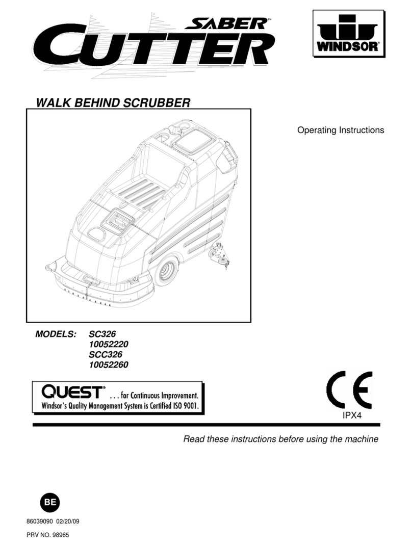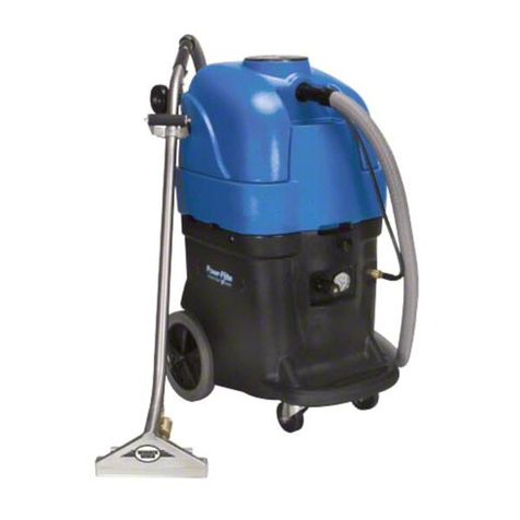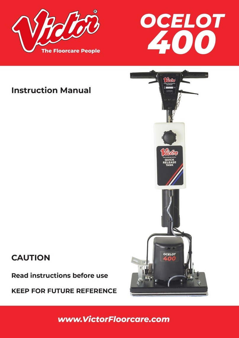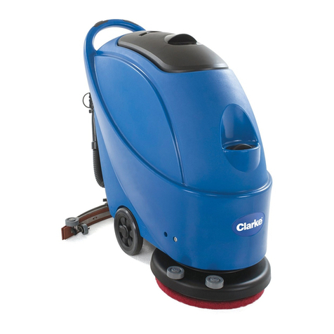
SCRUBBER DRIER OPERATING INSTRUCTIONS
DOWDING & PLUMMER LTD. CALTHORPE
HOUSE, STOCKFIELD ROAD,
BIRMINGHAM B27 6AP
Tel: +44 (0) 121-706 5771 Fax +44 (0) 121-708 1052
These instructions contain important safety and operating information.
CAUTION: DO NOT USE THIS APPLIANCE BEFORE READING THE INSTRUCTIONS.
The machine should be used in accordance with these instructions. If you are unsure on any point covered in this leaflet please contact the supplier or Dowding & Plummer Ltd.
This appliance is suitable for use in schools, hospitals, office buildings and any other safe hardfloor area.
SAFETY INFORMATION
1. Any person intending to use this machine must read and understand all of the information contained in this
document prior to use.
2.CAUTION: This machine is NOT suitable for picking up hazardous dust or flammable materials.
Before starting this machine it is important to remember:
A) This machine should only be used by trained operators.
B) Do not use this machine unless it is in a safe condition.
Check the cable and plug for damage before use, and if necessary, replace with a new cable pack.
NOTE: Only use “Victor” approved cable from our agents or direct.
C) Always keep the cable away from the brush. Hazard may occur in machine runs over power supply cord.
D) Always work within the cable length to avoid cable stress or damage.
E) When using a solution tank ,always empty the tank after use in a safe, suitable approved location.
F) Never use dirty brushes or allow brush to become over soiled before changing.
G) This machine has been designed for use with brushes supplied by the manufacturer. The fitting of other
brushes may affect its safety.
H) Check that the voltage on the serial number plate is suitable for the supply available.
I) DO NOT remove the supply cable from the cable harness / cable clamp
J) This appliance must be earthed. The wires in the mains lead are as follows:
Blue: - Neutral. This is connected to the terminal N
Brown: - Live. This is connected to the terminal L
Yellow / Green: - Earth. This is connected to terminal E
K) Always remove plug from the mains socket outlet before carrying out any routine
Maintenance, cleaning, brush or drive board attaching/removal and power cable replacement.
Products bearing this symbol should not be disposed of in your general waste. Dowding and
Plummer Ltd. Is a registered producer under the WEEE Directive (number WEEE/ABOO435Y/PRO)
and has procedures in place for dealing with end of life treatment and disposal of obligated
equipment. Please contact the company or visit our website for more details.
The Floor Care People
ISS13 -Nov 2008
PRODUCT SPECIFICATIONS
VOLTAGE: 220/240V
BRUSH DIAMETER: 500mm
BRUSH SPEED: 175 rpm
WORKING DOWN FORCE 35 KG
SOLUTION TANK: 40 Litres
RECOVERY TANK: 40 Litres
DRYING WIDTH: 750mm
CABLE LENGTH: 24M
VAC MOTOR: 1150W
HEIGHT: 1100mm
WIDTH: 570mm
LENGTH: 1000mm
WEIGHT(EMPTY): 73Kgs
WARRANTY POLICY
With the exception of Distributors, this warranty applies to the original
purchaser of the product from Dowding & Plummer Ltd.,(The Company) for
the following periods:
Vacuum Cleaners – Motors 2 Years, all other components 1 Year
Rotary Floor Machines – Motors 2 Years, all other components 1 Year
Scrubber Driers – Control Unit and Tanks 2 Years, all other components 1
Year
Carpet Extractors – 1Year
Battery Burnishers – 1Year
Specialist Machines – 1 Year
This warranty excludes normal maintenance parts and consumables such
as hoses, filters, drive belts, floor tools, cables, capacitors, relays, skirts and
pads etc. that are considered replaceable during the normal working life of
the machine. This list is not exhaustive.
The warranty period commences from the date the goods are
purchased by the user.
All warranty claims must be processed through the Distributor from
whom the equipment was purchased.
The Distributor will be responsible for the service, maintenance and
repairs during the warranty period.
The Distributor will co-operate with the purchaser throughout the
warranty claims procedure and will arrange any necessary repairs
using genuine Victor parts.
If the original Distributor is no longer available to fulfil his obligations,
or if you did not make your original purchase through a distributor, the
Company should be contacted and given details of proof of purchase
and full details of the claim in order that the claim may be processed
without delay.
Any warranty claim can only relate to the specific part that is proven
to be at fault and for which a replacement will be supplied but cannot
be extended to constitute a claim against the complete appliance.
The Company will supply the Distributor with any warranty parts
required subject to the claim being validated after return of the faulty
items in accordance with the Company's Conditions of Sale.
All replacement parts are guaranteed for a period of 6 months.
Claims will not be accepted if they are the result of fair wear and tear,
misuse or abuse of any kind, acts of God, damage in transit other than
original product delivery, failure due to lack of proper care or
maintenance or failure to comply with safety guidance.
No replacement will be given unless the appropriate evidence of the
validity of the claim has been provided to the satisfaction of the
Company.
The Company reserves the right to charge for any unnecessary work
carried out as a result of an invalid claim.
No variation to this warranty may be made or implied by any member
of the Company, its Distributors or representatives unless such
variation is in writing and authorised by the Company.


