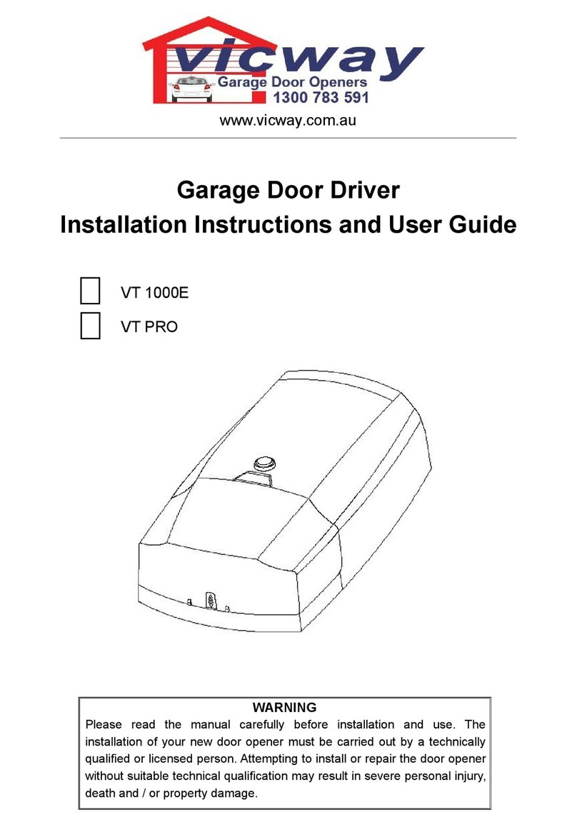
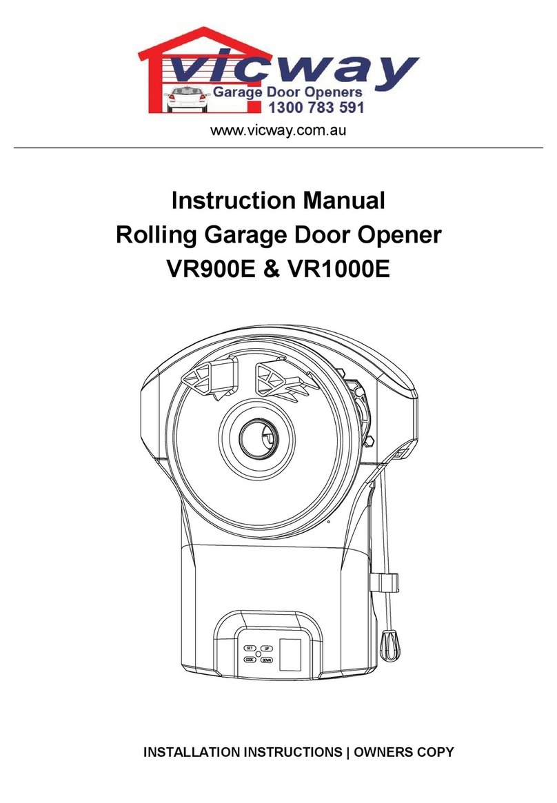
Vicway V-380G User manual

All rights reserved
.,
vlclIVay
GARAGE DOOR OPENER
Installation
Manual
and
Owner's
Guide
J
: I
(E
RoHS
CN27868
V·380G/V·390G
V&S
Roller
Doors
Pty
Ltd
20
Earl Street AIRPORT WEST VIC 3042
TEL: (03)
93386698
PLEASE READ THE MANUAL CAREFULLY BEFORE
INSTALLAllON
AND OPERATION

Contents
A.
Inventory 3
B.Function Introduction ···4
C.' Assembly Procedure··· ··5
D.
The Main Body and Program
Panel··
···9
E.
Wiring Diagram for Infra-Red
Beam··················10
F.
Programming
·11
G.
Programming
of
Transmitters ·18
H.
Technical Specifiications 19
.I. End
User's
Gu
ide ·
.'
20
J. Assembly
of
the Rail
in
2 Parts 22\
K.
Annex:Wiring Drawing 24
1.

A. InventoryThe garage
door
opener is packaged in
two
cartons which
contain the openerpack and the rail assembly pack illustrated below.
IMPORTANT SAFETY INSTRUCTIONS OpenerPack
.&WARNING-IT IS VITAL
FOR
THE SAFETY
OF
PERSON TO
FOLLOW
ALL INSTRUCTIONS
SAVE
THESE INSTRUCTIONS
<>
Do
not
allow children to
play
with controls;
<>
Keep remote controls away from children;
<>
Watc.h the moving door and keep people away until the door is
completely open
or
closed;
<>
Frequently
examine the installation, in
particular
cables, springs
I
I
and
mountings, for signs
of
wear, damage
or
imbalance. Do
not
use
I:
if
repair
or
adjustment is
needed
since a fault in the installation
or
an incorrectly
balanced
door may cause injury.
Appearance
Name
QTY
"
Opener
1
;
~::-
~-
:
...
:
Manual
1
e
Transmitter
2
~
Wireless
Wall
Control
1
~
Curved
Door
Arm
1
~
Mounting
Strap
2
~
~o
Support
Bracket
1
E:B
Support
angle
<> <>
I
~
"u"
Bracket
3
~
Header
Bracket
1
~
Door
Bracket
1
Pack
of
Assorted
Fasteners
6xl5
Hexagon
H~ad
Driving Screw
c:o
(8x) 6x80 Screw with Hexagon
Nut
/(lx)
8x25Inserted
Pin
~
(Ix)
3x20
Cotter
Pin\'-
(Ix)
Plum
Offset
Ring
II
(Ix)
lEi!
8x20
Screw
with
Hexagon
Nut
@
!
(6x)
RailPack Pre-Assembled Rail
Rail
(Ix)
Straight DoorArm
(IX)V
......
Chain/Belt
(Ix)
Emergency
Cord
(Ix)
....
Trolley
(Ix)
....
~
2
3·

B. Function Introduction
C.Assembly
Procedure
Intelligent
Computerized Control
Motor
Self
Diagnosis
Cryptoguard
Alarm
Device
Emergency Release
Additional Safty
Device
Automatic
closing
door
2000
cycles
alarm
Intelligent
computerized
precise
travel
positioning; timely force detection, reversion
occurs
when
obstacles
are met.
Low
noise,soft
start,slow
stop
protect
the
motor
and
ensure
a long
service
time.
Operational Mode and digital menu
is
displayed
on
the
control
panel
and
is
self-monitoring.
L = Normal, F = Interrupted, H = Fail in reading
A =InfraredRay State.
Rolling
code technoloY'provides
billions
of
code
combinations
and
makes
every
remote
control
a
unique
one
that
protects
against
unauthorized
access~
.
--
The
alarm
will
sound
if
the
door
is
left
open
for
over
19 minutes.
The
alarm
stops
when
the
door
is
closed
again.
(Refer
to F-7
on
P.14)
-.-
The
doo
can
be
manually
operated
by
pulling
down
on
the
emergency
release
rope
in
case
of
power
faulure.(Refer
to
C-4
on
P.8)
Safetyfurther ensuredwithadditionalaccessory
photocells.(Refer
to E
on
P.1
0).
The automatic closing time
of
the door canbe
set from 30 seconds to 240 seconds.
(Refer
to F-8
on
P.14)
When
the
operator
has
run
2000
cycles,
it
will
beep
to
remind
the
user
to
maintain
the
mechanical
system.
(Refer
to
F-9
on
P.16)
4
&
IMPORTANT SAFETY INSTRUCTIONS
FOR
INSTALLATION
WARNING-INCORRECT INSTALLATION CAN LEAD TO SEVERE INJURY
FOLLOW ALL INSTALLATION INSTRUCTIONS
o Before installing the drive, remove all unnecessary ropes or packing and disable
any equipment
which
is not
needed
after installation
of
the drive;
o Before installing the drive, check that the door is in good mechanical condition
and correctly balanced, and that it opens and closes properly;
o Install the actuating
member
for the manual release at
height
less
than
1.8m;
o
Install
any fixed
control
within
sight
of
the
door
but
away
from
moving
parts
a~d
at a height
of
at least
1.
5m;
o Permanently fix the labels warning against entrapment in a
prominent
place
or
near
any fixed controls;
o Permanently fix the label concerning the manual release adjacent to its actuating
member;
o
After
installation, ensure
that
the
mechanism
is
properly
adjusted
and
that
the
drive
reverses
when
the
door
contacts
a
40mm
high
object
placed
on
the floor
o
After
installation,
ensure
that
the
parts
of
the
door
do
not
extend
over
public
footpaths
or
roads;
after
installation,
ensure
that
the
drive
prevents
or
stops
the opening movent
when
the door is laded
with
a mass
of
20kg, fixed centrally
on
the
bottom
edge
of
the
door
(for
drives
that
can
be
used
with
doors
having
openings larger
than
50mm
in diameter)
o
Install
the
drive
at
height
no
less
than
2.5m.
S·

C-1
Essential Tools C-3 How
To
Fix The BodyAnd The Rail
[I]~rnJrn[IJg~~
C-2 Connecting The Body With The Rail
Rail
6Xl5Driving
scre
U Type bracket
I:
I,
I
Standard
6Xl5driving
screw
Rail
Special
Lh
(The special onewith a micro switch should
be
mountedreferring to the figure)
6
7'
l
,'"_

; I
I I
: I
'!
D.
The Main Body and Program Panel
C-4.
How
To Open The
Door
Manually
, i
Rail
Trolley
Rope
In
the case of power failure-
(l).
When the door is in the closed position:
Pull down on the rope and dis-engage the clutch, this will allow the door
to
be
lifted with ease.
(2). When the door is in the open position: Light for the garage
Pull down on the rope once, this will allow the door to move downward
to the closed position.
Cover panel
Indicator for code
Key for code key for adjustm'ent
So
po
0+
0-
settinl:!!
and signal receiving
!
If power recovers-
Operate the handheld transmitter or the wall control again, the clutchwill
be
re-engaged automatically.
Function Adjustment
it. (NB:Ifthe rail
is
I-section type, the system features the self-lock function but
2-sections
<;loes
not.)
Indicator for work procedure and working state
9
8

E.
Wiring Diagram For Infrared Beam
E-1
Infrared Ray Emitting And Receiving (OptionalAccessories)
a.
Connections
as
follows
Mainpanel
Infraredray radar
Wiringdiagram
L:hIfyour
opener is installed without photocell, you must connect terminals IR to
GND with a short cable, otherwise the opener will not be power operated(these 2
terminals have been connected at factory).
L:h
If
your opener is installed with photocell, please remove the short cable connecting
betweenIR and GND, otherwise the photocell can not work.
I
"
I
b.
Specification
'I
Detectingway Maxdistance Volt Current Output way
Emitting and receiving 12m 12-24V
lS0mA
NO
INC
E-2 Infrared Ray Instruction
When
the
door
is
closing
and
the
infrared
ray
beam
is
interrupted,
the
infrared
ray
works
and
the
door
will
stop
immediately.
But
when
the
door
is
opening,
it
does
not
work.
10
·F.
Programming
F
-1
Prepa
re
-
a.
Gently move the door
to
engage the trolley so that the opener can
drive the door
b.
Turn on the power, the lightwill come on, the unit will 'beep'
once and the display shows "0" in cycles.
L:h
(If
the finalize programming is not carried out, the setting will be deleted
automatically.
If
wrong information has
been
programmed,
you
can
turn
the
power
off
and then
turn
it on again to reset referring to the following.)
F-2 Up Limit Setting
So
=+
-
p-
I
01
=-
Press
key"p"
.(about 5 seconds) -
So
p=
-+
Q-,
--
-
Press
11+11
-
Or
press
,,_u
-
So
=+
0
p=
=-
The unit beeps once
and shows "1"
~...
':,1
t
....
~
Doorup
Doordown
_I
SO
I
~!t=+
p-
=-
Press "p" ,"1" flashes
-
_ISOI
11=+
p-
=-
-when the door rises to an ideal
position,press key
uP"
to save
the Information.
L:h.
(NB:The saved informationhas no effect ifthis performance
is
used for down
limit setting) ,
L:h
The up limit setting must be programmedbefore the down limit setting
11

--
-
-
-
-
-
-
F-3
Down Limit Setting
r-5
Force
Level
Setting
& The unit has been factory set at level 4, resetting by endusers is not required.
So
=+
So
-+
,~
So
I
~?1-+
- -
p_
-c
p=
I
I?I
021
=-
p=
-c
=-
So
-+
So
-+
So
=+
ILIl
j --
Press 11_11 0
=-
Press "+"
to
show
"2"
Press "p" ,"2" flashes }
p=D
p=
L-JJ
p-
-'
=-
=-
Orpress
"+"
I
'J
Press"
+"
to show "4" Press "p" , it shows"
J"
-..
Press "+", or Press
"_II
So
=+
1-to
select
the
level
r
p_1
21
-i
=-
t
...
~DDOr--nlr--nl
~
,
-,
L..dJ~
-
When
the
door
descends
to
DoorDown
an
ideal
posi
tion,
after
2 (Set
In
.t
lactory)
Or
DoorUp
seconds
press
key
"P" to
......
save
the
information
....
Force level High
& (NB: The saved informationhas no effect
if
this performance is used for up
limit setting)
Low
s=
=+
&
(If
the force level is set too low, the door moving will
p-
GJ
=-
F-4 Operating Force
Learning
be affected when the mechanical structure
ofthe
door
is not well-balanced. )
Press."p" to save the setting
So
r--5l
-+
So
~=+
p_
L--2
1-
-t
i"r-
F-6
Transmitter
Control
ButtonSetting
(default:2)
p=L1J
=-
=-
s=
-+
Press n+" , shows "3" Press "p" ,"3" flashes Doorrises automatically
s=
r-:I1
=+
s=
I
?s-+
-
-
p=
I
sl
p_LJ.J
p=
=-
=-
=-
So
=+
...
So
=+
,~
Press "+"to show "5" Press
up",
"1"
flashes, it
-...
Press
('+",
"2"
flashes,itmeans
--
p_131
p-
0
--'
-means only one button
of
the more than one button
of
the
=- =-
transmitter
can be memorized. transmitter can be memorized. Now
) Now
if
the first button
of
the
if
the first button
of
the transmitter
tra'nsmitter is memorized, and is memorized, and the user
err
Press "p" after
stops,
Doordescends Press "P" to save the the
user
programmes the second programmes the second button
of
press "p" again information, refer to
it.
button
of
the transmitter, then the transmitter, then both buttons
the first button is deleted are memorized.
~
automatically.
(press"
-"
to
choose"
1"
)
s=
r--El
=+
& (After the above basic setting, the user can now carry out the finalizing step f
f
to finalize the
programming)
I
i
p_
L..2J
=-
Press
key
II
p
l!
to
show
"51!,
save
the
setting.
12 13.
L

F-7 Alarm Setting
(The
factory set
at
"off"position)
Sc::::>
\~'"
~+
Sc::::>
-+
S
c:::>
em
-+
: ,
---+
-+
0
J~
LEJ
rn
p~
/ \
~-
p~
~-
p-
~-
Press "+" ,itshows 1,itmeans
Press "p", it shows
O,it
means
-+
the alarm setting is
off
the alarm setting is on.
Press
"+"
to show "6"
-+
.6
If
the
setting
is
on,
the
motor
will
start
to
beep
when
the
door
Sc::::>
~+
is
open
for
over
10
minutes,
itwill
beep
for
30
seconds
every
51
10
minutes)
p_
1
~-
.6
Exitway for the
sounding
alarm
Press "P" againto save the
Press
the
door Control button
to
close
the
door
fully.
setting
F-8 Automatic Closing Time Setting
(The
factory set at "off"position)
Sc:::J
~-+
Sc::::>
~+
Sc::::>
-+
~
---+
-+
L.:Jdj
p~
D,
'
p=~
~-
p-
~-
~-
Press"+" to
show"
1"to
turn
Press
"+",
shows "7"
---+
Press"P" to show "0" ,
---+
onthe function, it also means
itmeans the function is
off
the auto closingtime is 30
seconds
14
Press "+"" "-" to choosethe time according to the following drawings, 8 means 240 seconds(Maximent),
7 means 210 seconds etc.
Sc:::J
-+
Sc::::>
-+
Sc::::>
-+
r--5l
~
IDl
p~
L!;j
----. ----.
p~
L2J
p~
L....=!J
~-
~- ~-
Sc:::J
-+
Sc::::> Sc::::>
r--cl
-+
~-+
----. ----.
p=
I
sl
Pc:::>
l-.QJ
p
~
L-----.!J
~-
~-
~-
Sc:::J
-+
Sc::::>
----.
I D
-,
~+
II5l
p~
LQJ
~-
p-
'
~-
Press key
"p"
to show
"7
"and
exitthe program according to
the manual after choosing the
time
of
automatic closingthe
dooL .
.6
The motorbeeps for 20 seconds before the door starts
to
close automatically, at the same
time the light flashes. When the door starts to close, the motorbeeps, the light keeps on
but stops flashing. Afterthe door
is
closed, the motor stops beeping, and the light keeps
on for 3 minutes.
15.

F-9 2000 Cycles Alarm Setting
(The factory set at "off"position)
So
-+
So
""
=+
So
C1J:-+
:,
p=
I
BI
=-
-
p-
rn
=-
-
p=
"
=-
-
Press
":til,
shows
"8"
Press "p", it shows
O,it
means Press
"+"
,it shows
l,
the function is
off
-it means this function is on.
Lb.
Aftera period oftime
in
use, regularly check
to
see
So
=+
whether the door is level when opening/closing,
p-~
=-
whetherthe spring has enough force
to
raise the
door.
Add suitable amount oflubricant
to
all moving parts
Press "p" to save the setting regularly.
Ii
Lb.
Exit
way for the sounding alarm:
tum
off
the
power
then
switch on again
Or
press the door control
button
for 5 seconds
16
F-10 Finalize Programming
Lh
(NB: this finalizing step
must
be
carried out, otherwise the
saved
information
will
be
lost)
The
user
has two
ways
to
exit
finalize
programming
as follows:
Wayl:
s=
=+
S=
=+
s=
=+
-,
f---
OJ]
p-
0
-,
=-
-
D
p=
0
p=
=-
I
--
-
Press
II
_ "
to
select
111
" Keep pressing
"p"
for
"0" is
shown
in
cycles
to
5 seconds complete the programming
-and enter resting state
of
the opener
Way
2:
So
=+
So
=+
-
p=
I
01
D
=-
p-
=-
Afteroperating force learning
"0"
is
shown
in
cycles
to
(referto F-4 on
Pl2),when
the complete the programming
-
user fmishes any steps
of
the
and
enter
resting
state
of
menu,press
"p"
for 5 seconds the
opener
17

G. Programming
of
Transmitters
G-1
Code
s-
~+
Sc>
-
--.
--.
I"
"1
c:::>
+
O]
P~
LII-'
Pc:::>
J
~-
~-
Press "s"
--.
"0"
will
be
seen
on
the left
--.
Press any keytwice,
side
of
the
display,
and
coding is completed.
disappears immediately.
6
Note:
The
unit
can
memorize
maximum
40
transmitters.
6
At
this time,
the
code
has
been
successfully set
if
the
opener
works.
Other
transmitters
can
be
set
as above.
G-2
Decode
s-
D
~+
s-
10
I
~+
~~
c:::>+
--.
- D
P~
~-
P~
~-
Pc>
~-
Press & hold "s"
--.
"0" will
be
shown
on
the
--.
Keep pressing the keyuntil
for 8 seconds
left
side
of
the
display.
"0" has disappeared.
By
now, no transmitters can operate the openerunless
re-coded.
6 NB:
For
securitypurpose
if
atransmitterhas
been
lost it mustbe decoded andthe
new
transmitterencoded as above, so that the lost one
can
not
operate the
door anymore.
18
H.
Technical Specification
H-1
Model and Recommended Usage
Model Voltage(v) Area
of
the door(m2
)
~urrounding
difference
InteD1perature(~)
V-380G 190-240
~
IS
-20-S0
V-390G 190-240
~
19
-20-S0
H-2 Guide Rail and Available Sizes
Model Total length Travel
of
the rail
~eig~t
of
the door
In risIng
LK/PK-3000
3020mm 2S00mm <2200mm
LK/PK-3300
3320mm 2800mm <2S00mm
LK/PK-3600
3620mm 3100mm <2800mm
LK/PK-3800
3820mm 3300mm <3000mm
H-3 Specification List
Power 150W
/V-380G;
200W
/V-390G
Standby mode
with
the
light
off, 8W / V-380G/ V-390G
Pulling force 1100N / V-380G; 1500N / V)390G
Controller CPU
Controlling method Impulse inducting
Motor 24V.DC.
Light 25W,
E14,
V-380G/ V-390G
Speed
of
the door
11
cm/second
Fuse model Power fuse
1:
2.SA; Light fuse
2:
2.SA
Transmitter
frequency
and
distance
433 MHz/openspace'SOm
Drive Chain
Protecting method Keep in dry room
19 .

I.
End User's Guide
1-1
Care
Of
The Opener
a. V-3
80G
/ V-390G type
opener
is an
environmentally
friendly
product
generally
requiring
a
minimum
of
maintenance
in
normal
use.
b.
For
the
first
operation,
please
examine
the
drive
system
to see
whether
it
moves
easi
ly(Release
the
clutch,
push
and
pull
the
door
manually)
c.
Aftera period
of
time inuse, regularly check to see whether the door is level
when opening/closing, whether the spring has enough force to raise the door.
Regularly
lubricate
all the
moving
parts.
d.
ill
the event
of
powerfailure the operator can search for the program memory. When
the power
is
restored, press the button
of
the transmitter once, the door will
rise.
I!
:1
~.
,~,
....
--
t
The door stops moving When the power is restored According to the program
in the event
of
a power _ press the transmitter, the - memory, the doorwill rise
Failure. door moves up. to the up limit position and
then stop.
1-2
Normal Operation
a.
Remote
Control
--Opening,
closing
or
stopping
can
be
achieved
by
the
push
of
a
single
button
on
the
transmitter.
b.
Manual
operation--
In
the
event
of
power
failure,
opening
or
closing
of
the
door
can
be done
by
hand
once the clutch is
released. (Please refer to
P.
8)
20
1-3
Trouble
Shooting
Fault Causes Deal With
The opener does notwork
1.
The plug is not securely fitted
2.Thefuse is blown
I.Checkby a technician
2.Replace the same type
of
fuse by a technician
The
door does not
work
I.N
0 code has been set
2.The battery is out
of
power I.Re-code referring
to
G-I on P.l8
2.Replace with
~ew
battery
Remote control distance
is too short The battery is not powerful enough Replace with a new
one
of
the same model
The
chain
moves,
but
the
door
does
not
The clutchmay be unlock ed
Lock
the
clutch
referring
to C-4 on P.8
The
alarm keeps beeping I.Door is open too long
2.2000
cycles alarm
I.Close the door
2.Turn
off
the power, then
recover again
The
door
is
not
at
the
position
when
opened
or
closed,
or
not
working
Failure inset-up Set again
referring
to F
on
P.II
The
door
does not
work
in
normal,
and "H" is
shown
on
the screen Computerfailure due to humidity Dry out the unit
(by a technician)
Sudden stop
or
bounce
in working, and "F" is
shown on screen
1.
The
torque
spring
is
distorted
2.0bstruction
is
met
3.
The
power
is
not
stable
1.
Adjustthe torque spring by
a technician.
2.
Adjust the resistance to a
proper level until
"F"
disappears
In
working,
a
grating
sound
can
be
heard
Lack
oflubricant
between the
rail and the clutch after a long
period
of
use
Add suitable amount oflubricant
or wax
to
the position between
.the rail and the clutch
The
chain
has
come
loose
and
is
noisy
Looseness
of
the chain because
of
being used for a long time without
lubricant between the rail and the
Suitably fasten the bolt on the
spring, holding the chain in
place and lubricate it
clutch
(Referto@on
P23)
~
NB:
To
avoid being electrocuted, only a professional technician is allowed
to touch the wires and components on the main panel.
21 .

J.
Assembly
of
the
Rail in 2
P~rts
CD
Open
tb~i8i1-a~sembly
pack
J 6I
® ,.1Infold the rail in the direction
of
the
arrow
I
I
I
,
® .Move the connector to the middle
of
the rail
and
between the position
_limits
:~~
Limiting
position
Limiting
position
22
".
®
@
®
G
.Tightenthe nutwith asleeve
of
cI>
13
,Adjustas the drawing shows
.
Finished·
23·

K.
Annex:
wiring drawing
V-380G:
Power
The socketfor
photoelectricity
CN2
CPU
The connector
for wired Mainpanel
~~+
~
(±)
Q
control
~
(±)
..
Cl
z
u
The connector for
infrared way
-ow
+ow
+H:J -H:J
Connector
The connector
The connector
Travellimit for the motor
switch
V-390G:
for reserve
battery
rTTT"'TT""TT"Tr
I
1...l.L.LL.l..Ll
I
Receiver
CPU Main panel
The connector
for wired
control
IRela
y I
IRela
y I
The connector
for the motor Power
l-<
Q)
8
l-<
~.
00
~
Cd
l-<
Eo--
24
This manual suits for next models
1
Table of contents
Other Vicway Garage Door Opener manuals