Videorec NTW User manual

EN
English - Instruction manual
IT
Italiano - Manuale di istruzioni
FR
Français - Manuel d’instructions
DE
Deutsch - Bedienungsanleitung
RU
- Руководство по эксплуатации
ENGLISH
NTW
Liquid-cooled housing for thermal cameras


EN
English - Instruction manual
ENGLISH
NTW
Liquid-cooled housing for thermal cameras

Contents
ENGLISH 1
1 About this manual ......................................................................................................... 3
1.1 Typographical conventions.................................................................................................................................. 3
2 Notes on copyright and information on trademarks.................................................. 3
3 Safety rules..................................................................................................................... 3
4 Identication.................................................................................................................. 4
4.1 Product description and type designation..................................................................................................... 4
4.2 Product marking ...................................................................................................................................................... 4
5 Preparing the product for use ...................................................................................... 4
5.1 Unpacking.................................................................................................................................................................. 4
5.2 Contents...................................................................................................................................................................... 4
5.3 Safely disposing of packaging material........................................................................................................... 4
6 Installation ..................................................................................................................... 5
6.1 How to open the housing..................................................................................................................................... 5
6.2 How to install the camera..................................................................................................................................... 5
6.3 Closing the housing................................................................................................................................................ 5
6.4 Installing the housing ............................................................................................................................................ 5
6.5 Cooling circuit........................................................................................................................................................... 6
6.5.1 Examples of system dimensioning.................................................................................................................................... 6
6.6 Front ange with air barrier................................................................................................................................. 7
6.6.1 Suggested air capacity and pressure................................................................................................................................ 7
7 Accessories..................................................................................................................... 8
7.1 Replacement of the front ange........................................................................................................................ 8
7.2 Installing the camera power supply kit ........................................................................................................... 8
8 Cleaning ......................................................................................................................... 9
8.1 Cleaning the window............................................................................................................................................. 9
9 Information on disposal and recycling........................................................................ 9
10 Technical data .............................................................................................................. 9
10.1 Mechanical............................................................................................................................................................... 9
10.2 Housing's window...............................................................................................................................................10
10.3 Electrical .................................................................................................................................................................10
10.4 Environment..........................................................................................................................................................10
10.5 Certications.........................................................................................................................................................10
11 Technical drawings .................................................................................................... 11

Instruction manual - English - EN
3MNVCNTW_1811_EN
1 About this manual
Read all the documentation supplied carefully before
installing and using this unit. Keep the manual in a
convenient place for future reference.
1.1 Typographical conventions
DANGER!
High level hazard.
Risk of electric shock. Disconnect the
power supply before proceeding with any
operation, unless indicated otherwise.
CAUTION!
Medium level hazard.
This operation is very important for the
system to function properly. Please read
the procedure described very carefully and
carry it out as instructed.
INFO
Description of system specications.
We recommend reading this part carefully
in order to understand the subsequent
stages.
2 Notes on copyright and
information on trademarks
The mentioned names of products or companies are
trademarks or registered trademarks.
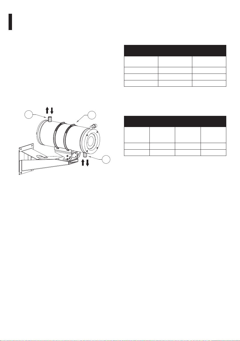
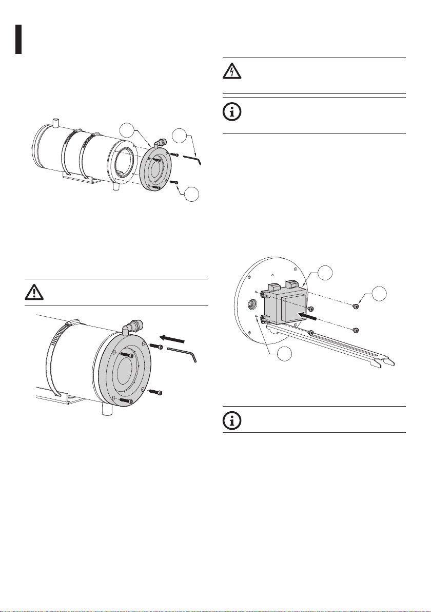
3 Safety rules
CAUTION! Device installation and
maintaining must be performed by
specialist technical sta only.
CAUTION!The electrical system to which the
unit is connected must be equipped with a
10A max automatic bipolar circuit breaker.
The minimum distance between the circuit
breaker contacts must be 3mm (0.1in).
The circuit breaker must be provided
with protection against the fault current
towards the ground (dierential) and the
overcurrent (magnetothermal).
• The manufacturer declines all responsibility
for any damage caused by an improper use
of the appliances mentioned in this manual.
Furthermore, the manufacturer reserves the right
to modify its contents without any prior notice.
The documentation contained in this manual has
been collected and veried with great care. The
manufacturer, however, cannot take any liability
for its use. The same thing can be said for any
person or company involved in the creation and
production of this manual.
• Before starting any operation, make sure the
power supply is disconnected.
• Be careful not to use cables that seem worn or old.
• Never, under any circumstances, make any
changes or connections that are not shown in
this handbook. Improper use of the appliance
can cause serious hazards, risking the safety of
personnel and of the installation.
• Use only original spare parts. Non-original spare
parts could cause re, electrical discharge or other
hazards.
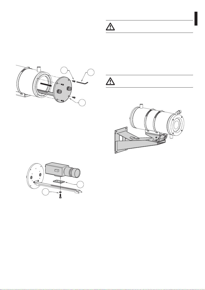
• Before proceeding with installation, check the
supplied material to make sure it corresponds
to the order specication by examining the
identication labels (4.2 Product marking, page 4).
• Equipment intended for installation in Restricted
Access Location performed by specialist technical
sta.

EN - English - Instruction manual
4 MNVCNTW_1811_EN
4 Identication
4.1 Product description and type
designation
The solid construction of this housing makes it
suitable for heavy-duty applications, such as the
surveillance of ovens, foundries and other high-
temperature environments.
The NTW housing, made of polished stainless steel
AISI 316L, can be equipped with a zinc selenide
(ZnSe) window designed for thermal video cameras
(with a wavelength from 7.5μm to 14μm), or a
sapphire glass window for shortwave thermal video
cameras (with a wavelength from 0.75μm to 4.5μm).
The NTW housing consists of a body with double
chamber for the circulation of coolant or cooling
air, closed by two very thick anges. The rear ange
enables cable passage using two cable glands
PG13.5. Two 1/2”GAS connectors control the input/
output of cooling uids.
The housing is equipped with a ange designed
to create an air barrier in front of the window, with
the dual purpose of preventing dust deposits and
reducing the temperature.
4.2 Product marking
See the label attached to the product.
5 Preparing the product for
use
Any change that is not expressly approved
by the manufacturer will invalidate the
guarantee.
5.1 Unpacking
When the product is delivered, make sure that the
package is intact and that there are no signs that it
has been dropped or scratched.
If there are obvious signs of damage, contact the
supplier immediately.
When returning a faulty product we recommend
using the original packaging for shipping.
Keep the packaging in case you need to send the
product for repairs.
5.2 Contents
Check the contents to make sure they correspond
with the list of materials as below:
• Housing
• Housing equipment:
• Allen wrench
• Spacers
• Bolts and screws
• Instruction manual
5.3 Safely disposing of packaging
material
The packaging material can all be recycled. The
installer technician will be responsible for separating
the material for disposal, and in any case for
compliance with the legislation in force where the
device is to be used.

Instruction manual - English - EN
5MNVCNTW_1811_EN
6 Installation
6.1 How to open the housing
Unscrew the screws (01) on the rear ange (02) using
the hexagonal wrench (03) provided.
Slide out the rear cover plate of the housing, taking
care to leave the sealing washer in its seating.
By doing so, you can access inside the housing
without dismantling the support bracket.
01
02
03
Fig. 1
6.2 How to install the camera
Open the housing as described in the relative chapter
(6.1 How to open the housing, page5).
Assemble the camera on the slide using the
insulating spacer (01) and the 1/4”screw and the
washer (02) provided. If necessary, use the spacers to
position the camera and lens correctly.
02
01
Fig. 2
Insert the cables through the cable glands and
electrically connect.
Ensure the cable glands are rmly fastened.
6.3 Closing the housing
Pay attention to the xing. Tightening
torque: 4Nm.
Close the housing by proceeding in the reverse
order to that described above (6.1 How to open the
housing, page5).
Pay attention not to damage the gasket.
Make sure that the sealing ring is correctly tted in
its position.
6.4 Installing the housing
Pay attention to the xing. Tightening
torque: 4Nm.
Fasten the housing to the bracket using the screws
provided.
Fig. 3

EN - English - Instruction manual
6 MNVCNTW_1811_EN
6.5 Cooling circuit
The housing is equipped with an input and output
joint on the cooling circuit, both of which are
threaded 1/2”Gas.
Installation and dispersal of heat requirements
mean the position of the input and output joints on
the cooling circuit must be adapted to the specic
situation.
The two joints on the cooling circuit placed near
the front (01) and rear (02) ange can be used
indierently for cooling liquid input and output.
If necessary, the housing can be rotated on its xing
base by loosening the two xing clips (03).
01
02 03
OUT/IN
IN/OUT
Fig. 4
6.5.1 Examples of system dimensioning
The following test data refer to use of water as
a cooling liquid, with an input temperature of
the housing of 20°C and a maximum ambient
temperature of 400°C.
WATER COOLING CIRCUIT WITH INPUT WATER AT A TEMPERATURE
OF 20°C
T environment
(°C)
Water ow rate
(l/min)
T inside housing
(°C)
200 2 32
300 2.2 41
400 6.5 44
Tab. 1
The following test data refer to cooling with air, at
an input temperature of the housing of 17°C and a
maximum ambient temperature of 80°C.
AIR COOLING CIRCUIT WITH INPUT AIR AT A TEMPERATURE OF
17°C
T envi-
ronment
(°C)
Air pressure
(bar)
Air capacity
(m³/h)
T inside
housing
(°C)
80 1 10 45
80 2 15 35
Tab. 2

Instruction manual - English - EN
7MNVCNTW_1811_EN
6.6 Front ange with air barrier
The ange with air barrier is equipped with a 1/4”Gas
thread joint and a reduction from 1/2”Gas to 1/4”Gas.
This joint must be connected to the circuit with
compressed air supplied by a compressor.
Fig. 5
6.6.1 Suggested air capacity and
pressure
Upstream of the housing , you are advised to install:
• a gauge
• an adjustment valve
• an optional lters unit (e.g. NXFIGRU) for
compressed air cleaning (ltration: 0.1μm).
This allows you to:
• know and adjust the pressure to supply to the
air barrier
• conduct simple maintenance.
Too high pressure values can cause
breakage of the window. Strictly comply
with the maximum values listed below:
• System pressure: 4bar max
• Recommended minimum pressure: 2bar
For example purposes, the system pressure-output
pressure and system pressure-air capacity graphics
are outlined which are useful for compressor
dimensioning. All the values must be considered as
purely approximate.
0
0.4
0.2
0.6
0.8
1
1.2
1.4
1 2 3 4
System pressure (bar)
Output pressure (bar)
Fig. 6
1
0
01 2 3 4
10
5
15
20
System pressure (bar)
Air capacity (m³/h)
Fig. 7

EN - English - Instruction manual
8 MNVCNTW_1811_EN
7 Accessories
7.1 Replacement of the front
ange
Dismantle the front ange (01) of the housing by
unscrewing the four screws (02) with the hexagonal
wrench (03) provided.
02
01 03
Fig. 8
Position the new front ange on the body of the
housing, paying attention the gaskets are correctly
inserted in their compartments to avoid damaging
them. Tighten the 4 screws using the allen wrench
supplied.
Pay attention to the xing. Tightening
torque: 4Nm.
Fig. 9
7.2 Installing the camera power
supply kit
Pay attention to the voltage used to power
the circuit. Depending on requirements use
the correct power supply kit.
To install the power supply kit for the
camera, there is no need to remove any pre-
installed component.
Usable power supplies:
• IN 230Vac ±5%, 50/60Hz - OUT 12Vdc, 400mA
• IN 230Vac, 50/60Hz - OUT 24Vac, 400mA
Open the housing (6.1 How to open the housing,
page5).
Position the power supply (01) corresponding to the
xing holes on the internal side (02) of the rear ange.
Fasten the power supply to the bottom of the
housing with the screws (03) provided with the
power supply kit.
03
02
01
Fig. 10
Connect the camera to the power supply.
Nominal section of the cables used: 2.5mm²
max.
Close the housing (6.3 Closing the housing, page5).

Instruction manual - English - EN
9MNVCNTW_1811_EN
8 Cleaning
8.1 Cleaning the window
We recommend using a soft cloth with neutral soap
diluted with water or specic products to clean the
glasses lenses.
Avoid ethyl alcohol, solvents, hydrogenated
hydrocarbide, strong acid and alkali. Such
products may irreparably damage the
surface.
9 Information on disposal
and recycling
The European Directive 2012/19/EU on Waste
Electrical and Electronic Equipment (WEEE) mandates
that these devices should not be disposed of in the
normal ow of municipal solid waste, but they should
be collected separately in order to optimize the
recovery stream and recycling of the materials that
they contain and to reduce the impact on human
health and the environment due to the presence of
potentially hazardous substances.
The symbol of the crossed out bin is marked
on all products to remember this.
The waste may be delivered to appropriate collection
centers, or may be delivered free of charge to the
distributor where you purchased the equipment at
the time of purchase of a new equivalent or without
obligation to a new purchase for equipment with size
smaller than 25cm .
For more information on proper disposal of these
devices, you can contact the responsible public
service.
10 Technical data
10.1 Mechanical
Housing manufactured in polished stainless steel
(austenitic stainless alloy steel resistant to corrosion
and heat):
• AISI 316L
• UNI 6900-71: X 2 Cr Ni Mo 17 12 2
• DIN 17006: X 2 Cr Ni Mo 17 13 2
• N° werksto: 1.4404
• AFNOR: Z2 CND 17-12
• BSI: 316S11
The screws utilised are in austenitic alloy stainless
steel, corrosion and heat resistant according to the
following standards:
• ISO: 7380
• AISI: 316
• ISO quality: A4
External body polishing
External dimensions (ØxL): 154x380mm (6.1x15in)
Internal usable area (WxH): 78x78mm (3.1x 3.1in)
Internal usable length: 345mm (13.6 in)
Internal usable length with camera power supply:
280mm (11in)
Flange thickness (back): 9mm (0.35in)
Gaskets: O-ring
2 x 1/2”GAS connectors control the input/output of
uids
1 x 1/4”Gas threaded joint with a reduction from
1/2”Gas to 1/4”Gas (ange with air barrier)
Cable glands: 2 PG13.5 (nickel-plated brass)
Unit weight: 10.2kg (22lb)

EN - English - Instruction manual
10 MNVCNTW_1811_EN
10.2 Housing's window
Usable diameter: 65mm (2.6in)
Zinc selenide (ZnSe) window
• Thick: 4mm (0.16in)
• Operating temperature: 200°C (392°F) max
• Spectral range: from 7.5μm up to 14μm
Wavelength [μm]
Transmittance
[%]
ZnSe 4mm, AR/AR
70
75
80
85
90
95
100
10 1187 7,5 8,5 9,5 10,5 11,5 12,5 13,5
9 12 13 14
Fig. 11 Zinc selenide transmittance.
Sapphire glass window
• Thick: 1mm (0.04in)
• Operating temperature: 400°C (752°F) max
• Spectral range: from 0.75μm up to 4.5μm
22,5
10,5
70
75
80
85
90
95
100
1,5 3 3,5 4 4,5 5
Transmittance [%]
Sapphire glass 1mm
Wavelength [μm]
Fig. 12 Sapphire glass transmittance.
10.3 Electrical
Camera power supply
IN 230Vac ±5%, 50/60Hz - OUT 12Vdc, 400mA
IN 230Vac, 50/60Hz - OUT 24Vac, 400mA
10.4 Environment
For installation indoors and outdoors
Maximum working temperature with water cooling:
• zinc Selenide glass: 200°C (392°F)
• sapphire glass window: 400°C (752°F)
Maximum working temperature with air cooling: 80°C
(176°F)
10.5 Certifications
Electrical safety (CE): EN60065
Electromagnetic compatibility (CE): EN50130-4,
EN61000-6-3
IP protection degree (EN60529):
• IP66
EAC certication

Instruction manual - English - EN
11MNVCNTW_1811_EN
11 Technical drawings
The measurements indicated are expressed in millimetres.
78
26 345
280
9
380
130
Ø 101.6
M5
115
116.5
78
60
94
164
Ø 65
Ø 154
A
20
A
87
B
B
B - B
A - A
1/2" GAS
1/4" GAS
28
28
1/2" GAS
1/2" GAS
USABLE AREA
USABLE
AREA
WITH POWER SUPPLY
FIXING BASE
Fig. 13 NTW.

MNVCNTW_1811_EN
Headquarters Italy Videotec S.p.A.
Via Friuli, 6 - I-36015 Schio (VI) - Italy
Tel. +39 0445 697411 - Fax +39 0445 697414
Email: [email protected]
France Videotec France SARL
Immeuble Le Montreal, 19bis Avenue du Québec, ZA de Courtaboeuf
91140 Villebon sur Yvette - France
Tel. +33 1 60491816 - Fax +33 1 69284736
Email: info.fr@videotec.com
Asia Pacic Videotec (HK) Ltd
Flat 8, 19/F. On Dak Industrial Building, No. 2-6 Wah Sing Street
Kwai Chung, New Territories - Hong Kong
Tel. +852 2333 0601 - Fax +852 2311 0026
Email: info.hk@videotec.com
Americas Videotec Security, Inc.
Gateway Industrial Park, 35 Gateway Drive, Suite 100
Plattsburgh, NY 12901 - U.S.A.
Tel. +1 518 825 0020 - Fax +1 518 825 0022
Email: info.usa@videotec.com
www.videotec.com

IT
Italiano - Manuale di istruzioni
ITALIANO
NTW
Custodia rareddata a liquido per telecamere termiche

Sommario
ITALIANO 1
1 Informazioni sul presente manuale ............................................................................. 3
1.1 Convenzioni tipograche ..................................................................................................................................... 3
2 Note sul copyright e informazioni sui marchi commerciali........................................ 3
3 Norme di sicurezza ........................................................................................................ 3
4 Identicazione ............................................................................................................... 4
4.1 Descrizione e designazione del prodotto....................................................................................................... 4
4.2 Marcatura del prodotto......................................................................................................................................... 4
5 Preparazione del prodotto per l'utilizzo...................................................................... 4
5.1 Disimballaggio.......................................................................................................................................................... 4
5.2 Contenuto .................................................................................................................................................................. 4
5.3 Smaltimento in sicurezza dei materiali di imballaggio.............................................................................. 4
6 Installazione................................................................................................................... 5
6.1 Apertura della custodia......................................................................................................................................... 5
6.2 Installazione della telecamera............................................................................................................................. 5
6.3 Chiusura della custodia ......................................................................................................................................... 5
6.4 Installazione della custodia.................................................................................................................................. 5
6.5 Circuito di rareddamento................................................................................................................................... 6
6.5.1 Esempi di dimensionamento dell'impianto................................................................................................................... 6
6.6 Flangia anteriore con barriera d'aria................................................................................................................. 7
6.6.1 Portate e pressioni d'aria suggerite .................................................................................................................................. 7
7 Accessori......................................................................................................................... 8
7.1 Sostituzione della angia anteriore .................................................................................................................. 8
7.2 Installazione del kit alimentatore per telecamera ....................................................................................... 8
8 Pulizia ............................................................................................................................. 9
8.1 Pulizia della nestra................................................................................................................................................ 9
9 Informazioni sullo smaltimento e il riciclo .................................................................. 9
10 Dati tecnici ................................................................................................................... 9
10.1 Meccanica ................................................................................................................................................................ 9
10.2 Finestre per custodia..........................................................................................................................................10
10.3 Elettrico...................................................................................................................................................................10
10.4 Ambiente................................................................................................................................................................10
10.5 Certicazioni .........................................................................................................................................................10
11 Disegni tecnici ........................................................................................................... 11

Manuale di istruzioni - Italiano - IT
3MNVCNTW_1811_IT
1 Informazioni sul presente
manuale
Prima di installare e utilizzare questa unità, leggere
attentamente tutta la documentazione fornita. Tenere
il manuale a portata di mano per consultazioni
successive.
1.1 Convenzioni tipograche
PERICOLO!
Pericolosità elevata.
Rischio di scosse elettriche. Prima di
eseguire qualsiasi operazione assicurarsi di
togliere tensione al prodotto, salvo diversa
indicazione.
ATTENZIONE!
Pericolosità media.
L'operazione è molto importante per il
corretto funzionamento del sistema. Si
prega di leggere attentamente la procedura
indicata e di eseguirla secondo le modalità
previste.
INFO
Descrizione delle caratteristiche del
sistema.
Si consiglia di leggere attentamente per
comprendere le fasi successive.
2 Note sul copyright e
informazioni sui marchi
commerciali
I nomi di prodotto o di aziende citati sono marchi
commerciali o marchi commerciali registrati
appartenenti alle rispettive società.
3 Norme di sicurezza
ATTENZIONE! L'installazione e la
manutenzione del dispositivo deve
essere eseguita solo da personale tecnico
specializzato.
ATTENZIONE! L’impianto elettrico al quale
è collegata l’unità deve essere dotato di
un interruttore di protezione bipolare
automatico da 10A max. La distanza
minima tra i contatti dell'interruttore
di protezione deve essere di 3mm.
L’interruttore deve essere provvisto di
protezione contro la corrente di guasto
verso terra (dierenziale) e la sovracorrente
(magnetotermico).
• Il produttore declina ogni responsabilità per
eventuali danni derivanti da un uso improprio
delle apparecchiature menzionate in questo
manuale. Si riserva inoltre il diritto di modicarne il
contenuto senza preavviso. Ogni cura è stata posta
nella raccolta e nella verica della documentazione
contenuta in questo manuale. Il produttore,
tuttavia, non può assumersi alcuna responsabilità
derivante dall'utilizzo della stessa. Lo stesso
dicasi per ogni persona o società coinvolta nella
creazione e nella produzione di questo manuale.
• Prima di eseguire qualsiasi operazione assicurarsi
di togliere tensione al prodotto.
• Non utilizzare cavi con segni di usura o
invecchiamento.
• Non eettuare per nessun motivo alterazioni o
collegamenti non previsti in questo manuale.
L'uso di apparecchi non idonei può portare a
gravi pericoli per la sicurezza del personale e
dell'impianto.
• Utilizzare solo parti di ricambio originali. Pezzi di
ricambio non originali potrebbero causare incendi,
scariche elettriche o altri pericoli.
• Prima di procedere con l'installazione, controllare
che il materiale fornito corrisponda alle speciche
richieste esaminando le etichette di marcatura (4.2
Marcatura del prodotto, pagina 4).
• L'apparecchio è destinato all'installazione in
una Posizione ad Accesso Limitato eettuata da
personale tecnico specializzato.

IT - Italiano - Manuale di istruzioni
4 MNVCNTW_1811_IT
4 Identicazione
4.1 Descrizione e designazione
del prodotto
La costruzione eccezionalmente robusta di questa
custodia la rende adatta alle applicazioni più gravose,
per la sorveglianza di forni, fonderie e ambienti in cui
si sviluppino alte temperature.
La custodia NTW, costruita in acciaio Inox brillantato
AISI 316L, può essere equipaggiata con nestra in
seleniuro di zinco (ZnSe) concepita per telecamere
termiche (lunghezza d’onda da 7.5μm no a 14μm), o
con nestra in vetro zaro per telecamere termiche
shortwave (lunghezza d’onda da 0.75μm no a
4.5μm).
NTW è costituita da un corpo con doppia camera
per la circolazione del liquido o dell’aria di
rareddamento, chiuso da due ange di grosso
spessore. La angia posteriore permette il passaggio
dei cavi mediante due pressacavi PG13.5. Due
connettori 1/2" GAS permettono l'entrata/uscita del
uido refrigerante.
La custodia è dotata di una angia predisposta per
creare una barriera d’aria davanti alla nestra con il
duplice scopo di impedire il deposito di polvere e di
ridurre la temperatura.
4.2 Marcatura del prodotto
Vedere l’etichetta posta sul prodotto.
5 Preparazione del prodotto
per l'utilizzo
Qualsiasi intervento non espressamente
approvato dal costruttore fa decadere la
garanzia.
5.1 Disimballaggio
Alla consegna del prodotto vericare che l'imballo
sia integro e non presenti segni evidenti di cadute o
abrasioni.
In caso di danni evidenti all'imballo contattare
immediatamente il fornitore.
In caso di restituzione del prodotto malfunzionante
è consigliato l'utilizzo dell'imballaggio originale per
il trasporto.
Conservare l'imballo qualora fosse necessario inviare
il prodotto in riparazione.
5.2 Contenuto
Controllare che il contenuto sia corrispondente alla
lista del materiale sotto elencato:
• Custodia
• Dotazione per custodia:
• Chiave esagonale
• Distanziali
• Viteria
• Manuale di istruzioni
5.3 Smaltimento in sicurezza dei
materiali di imballaggio
I materiali d'imballo sono costituiti interamente da
materiale riciclabile. Sarà cura del tecnico installatore
smaltirli secondo le modalità di raccolta dierenziata
o comunque secondo le norme vigenti nel Paese di
utilizzo.

Manuale di istruzioni - Italiano - IT
5MNVCNTW_1811_IT
6 Installazione
6.1 Apertura della custodia
Svitare le viti (01) poste sulla angia posteriore (02)
utilizzando la chiave esagonale (03) in dotazione.
Slare il fondo della custodia prestando attenzione
che la guarnizione rimanga in sede.
Così facendo sarà possibile accedere all'interno della
custodia senza smontarla dalla staa di sostegno.
01
02
03
Fig. 1
6.2 Installazione della telecamera
Aprire la custodia come descritto nel relativo capitolo
(6.1 Apertura della custodia, pagina5).
Montare la telecamera sulla slitta utilizzando il
distanziale isolante (01), la vite da 1/4”e la rondella (02)
in dotazione. Se necessario utilizzare i distanziali per
posizionare nel modo corretto telecamera ed ottica.
02
01
Fig. 2
Inserire i cavi attraverso i pressacavi ed eseguire le
connessioni elettriche necessarie. Assicurarsi che i
pressacavi siano ssati saldamente.
6.3 Chiusura della custodia
Prestare attenzione durante il ssaggio.
Coppia di serraggio: 4Nm.
Chiudere la custodia operando in maniera inversa
a quanto descritto precedentemente (6.1 Apertura
della custodia, pagina5).
Prestare attenzione a non danneggiare la guarnizione
di tenuta.
Assicurarsi che la guarnizione sia correttamente
inserita nella propria sede.
6.4 Installazione della custodia
Prestare attenzione durante il ssaggio.
Coppia di serraggio: 4Nm.
Fissare la custodia sulla staa utilizzando le viti fornite
in dotazione.
Fig. 3

IT - Italiano - Manuale di istruzioni
6 MNVCNTW_1811_IT
6.5 Circuito di rareddamento
La custodia è dotata di un raccordo d’entrata e uno
d’uscita del circuito di rareddamento entrambi
lettati 1/2”Gas.
Le esigenze di installazione e di smaltimento
del calore impongono di adattare la posizione
dei raccordi di ingresso e uscita del circuito di
rareddamento in funzione della specica situazione.
I due raccordi per il collegamento del circuito di
rareddamento posti in prossimità della angia
anteriore (01) e posteriore (02) possono essere
utilizzati indistintamente per l’ingresso o l’uscita del
uido di rareddamento.
Se necessario, è inoltre possibile ruotare la custodia
rispetto alla sua base di ssaggio allentando le due
fascette di ssaggio (03).
01
02 03
OUT/IN
IN/OUT
Fig. 4
6.5.1 Esempi di dimensionamento
dell'impianto
I seguenti dati sperimentali si riferiscono all’utilizzo
di acqua come liquido di rareddamento, con una
temperatura all'ingresso della custodia di 20°C e una
temperatura ambiente massima di 400°C.
CIRCUITO DI RAFFREDDAMENTO AD ACQUA CON ACQUA IN
INGRESSO A UNA TEMPERATURA DI 20°C
T ambiente
(°C)
Portata acqua
(l/min)
T interna custodia
(°C)
200 2 32
300 2.2 41
400 6.5 44
Tab. 1
I seguenti dati sperimentali si riferiscono al
rareddamento con aria, con una temperatura
all'ingresso della custodia di 17°C e una temperatura
ambiente massima di 80°C.
CIRCUITO DI RAFFREDDAMENTO AD ARIA CON ARIA IN INGRESSO
A UNA TEMPERATURA DI 17°C
T ambiente
(°C)
Pressione
aria
(bar)
Portata aria
(m³/h)
T interna
custodia
(°C)
80 1 10 45
80 2 15 35
Tab. 2
Table of contents
Languages:
Other Videorec Camera Accessories manuals