ARTHUR HOLM DynamicVision AHDVDOC01 User manual

DynamicVision Mounting Instructions DynamicVision
-Mounting Instructions Pg. 2-5
-Upholstery Instructions Pg. 6-11
AHDVDOC01

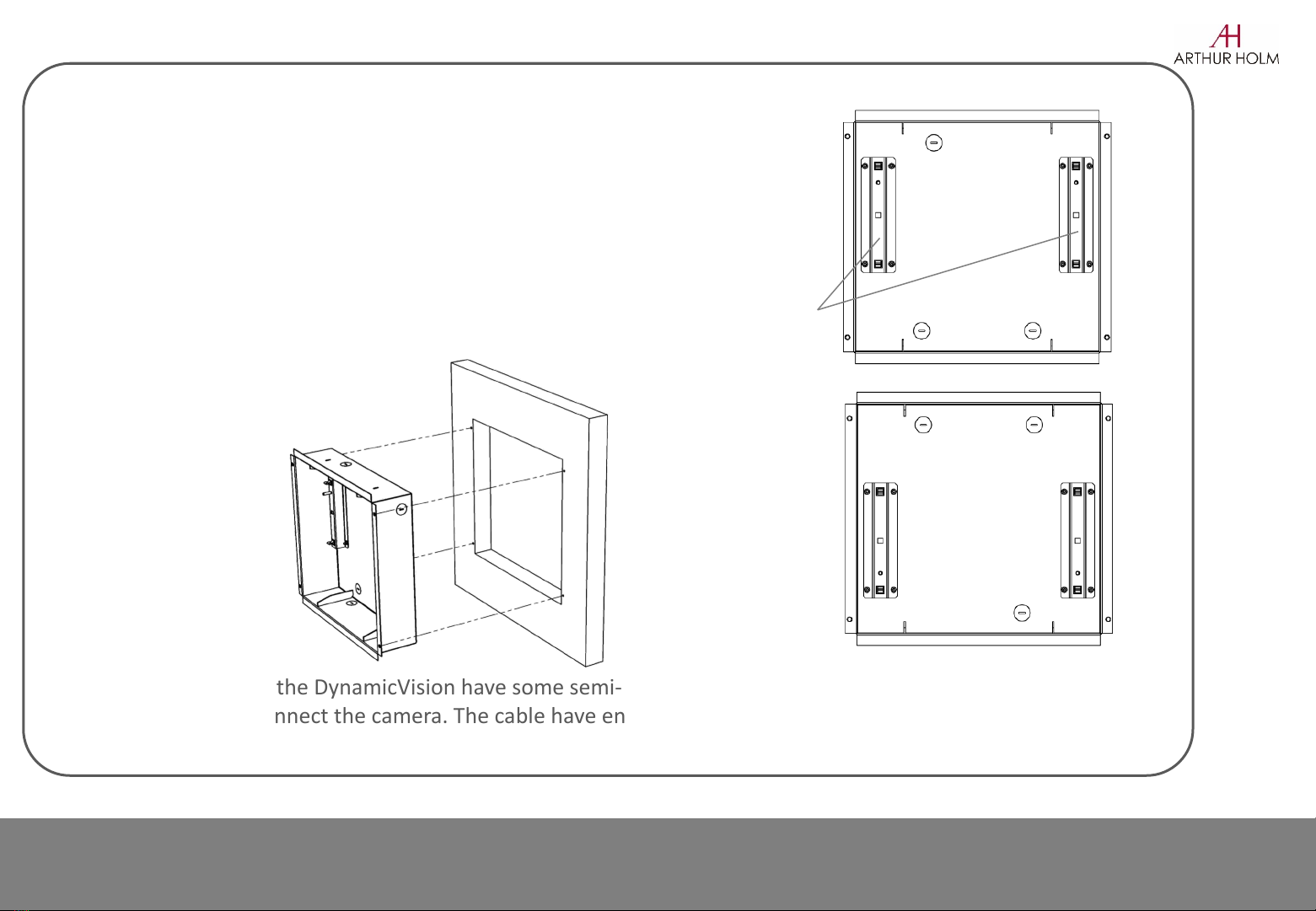
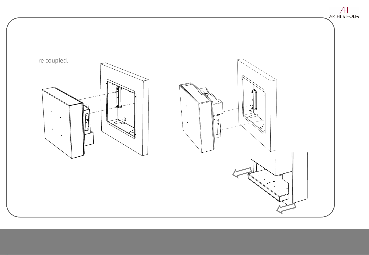
DynamicVision is supplied with the frontal lid made to be upholstered with
different fabrics. The necessary components to cover the lid are supplied
with the device except the fabric.
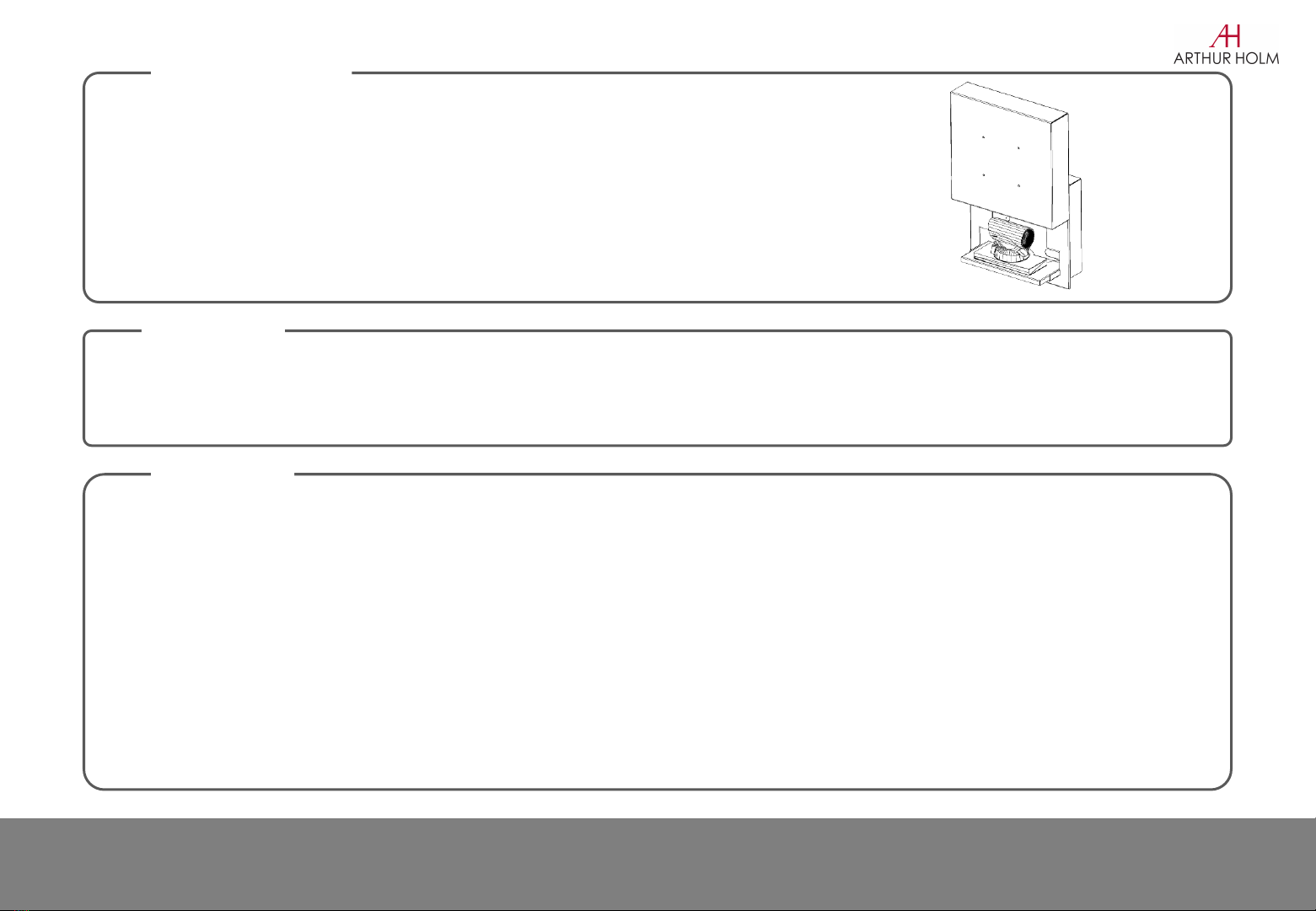
The hole pattern as well as the product dimensions are stated in the document
“General dimensions”.
ATTENTION
HOLE
INTRODUCTION
2
Manipulation of the product should be avoided, no stress should be applied to the product except from the
instructions given in this document. Cutting, drilling, soldering, adding of electrical and mechanical
components can cause danger and should be avoided by all mean. Not complying with these direction will
result in a lost of the Arthur Holm warranty. Albiral Display Solution S.L. shall not be held liable for any loss
or injury incurred as a result of modifications made to goods by anyone other than the supplier or the
supplier's authorised representative without the supplier's written permission. Such modifications shall be
deemed to terminate any further warranty obligations. Compensation will not be paid for wages, loss of
profit, waste of time, packing and transport or any financial liability resulting from defects in the goods.
(Albiral Display Solutions shall not be liable for any loss or injury caused by negligence.)
Information

Assembling Camera on DynamicVision 3
The DynamicVision camera tray has been equipped with carefully placed mounting holes to ensure the perfect alignment
of the camera respecting the horizontal view. These holes complies to a great range of camera mounting holes.
It should be intended to use the mounting holes for proper installation.
Should this not be possible, double-side tape can be applied.
1. Connect the power of
DynamicVision and open it.
2. Disconnect the power.
Unscrew the 2 nuts of the
tray
3. Fasten the camera by
means of screws or double-
side tape.
4. Assemble the tray with
the camera by screwing the
two nuts.

Installing DynamicVision 4
The MountingBox of the DynamicVision have some semi-die cut, break the needed one to pass the
cables trough and connect the camera. The cable have enough loop inside the DynamicVison to allow
the tray to do its movement.
Screw the Mounting Box to the wall using countersink screws.
Make sure the Mounting Box is aligned respecting the
horizontal view.
Depending on the DynamicVision ordered, the cover opens
upwards or downwards.
-If DynamicVision opens upwards the MountingBox must be
installed as in the picture “A” (see bracket position)
-If DynamicVision opens downwards the MountingBox must
be installed as in the picture “B” (see bracket position)
“A”
“B”
Brackets

2. Approach the DynamicVision to the Mounting Box
in order to connect the cables. Subsequently, insert
the device into the Box pressing it until the fastening
clips are coupled.
Attention: To extract DynamicVision of the
Mounting Box avoiding to damage the door, it is
necessary to pull the device holding it by the sides
of the tray.
5
Installing DynamicVision
“A” “B”

INFORMATION
PREPARING THE FABRIC
Fabric thickness shouldn’t be more than 0.3mm [0.01inch]. Otherwise, the tubes to hold the fabric should
have a smaller diameter.
•Cut a 550x700mm [21.6x27.5inch]rectangular piece of fabric
• Following tubes are provided for the upholstering: 2x360mm [14.1inch], 2x340mm [13.4inch] and
2x70mm [2.75inch]
•Smooth out the piece of fabric on a flat and clean surface and place the DynamicVision front lid over it,
ensuring that it’s centered and leaving 50mm [1.97inch] on the lower side as shown.
Upholstery Instructions 6
700
550
50
Provided tubes

Upholstery Instructions
Front Side
UPHOLSTERING
1. Push the fabric into the upper corner slots with the help of a card, make sure you pull it tightly so that
it is perfectly framed.
Pull the fabric tightly from
the inside of the corners
7

Upholstery Instructions 8
2. The tubes are used to trap the fabric into the U_shaped section on the edges of the lid.
3. Start upholstering the top side first using one of the 360mm tubes. Start by trapping the fabric in the
middle and then keep pressing to the sides.
UPHOLSTERING
U_shaped Tube
Fabric

Upholstery Instructions
UPHOLSTERING
Inner corners
3. Next upholster the bottom side, folding the inner corners neatly. It’s important to pull the fabric
tightly before trapping it into the U_shape section.
4. Do the same with the laterals, this time using the 340mm [13.4inch] tubes. Make sure the fabric is well
inserted in the inner corners. Remember to pull the fabric tightly before trapping the opposite lateral
9
Pull the fabric
from the inside
of the corners

Upholstery Instructions
UPHOLSTERING
5. Trappe the fabric in the smaller edges with the 2x 70mm [2.75inch] tube
6. You may trim an excess of fabric
10
Excess of fabric

Upholstery Instructions
UPHOLSTERING
7. The lid is now ready to be assembled
ASSEMBLING THE LID
Use the M4 nuts provided to assemble the lid to
the DynamicVision. Use a 7mm box spanner
11

www.arthurholm.com
Table of contents