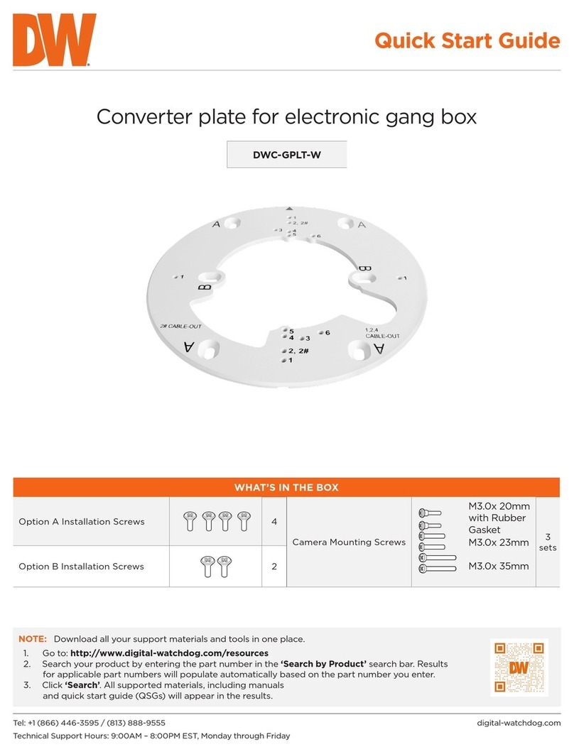
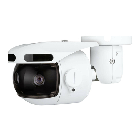
Digital Watchdog DWC-B7JUNCW User manual
Other Digital Watchdog Camera Accessories manuals
Digital Watchdog
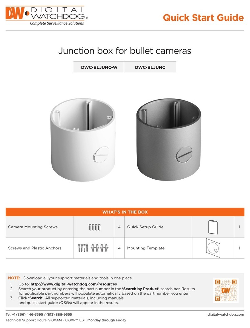
Digital Watchdog DWC-BLJUNC-W User manual
Digital Watchdog
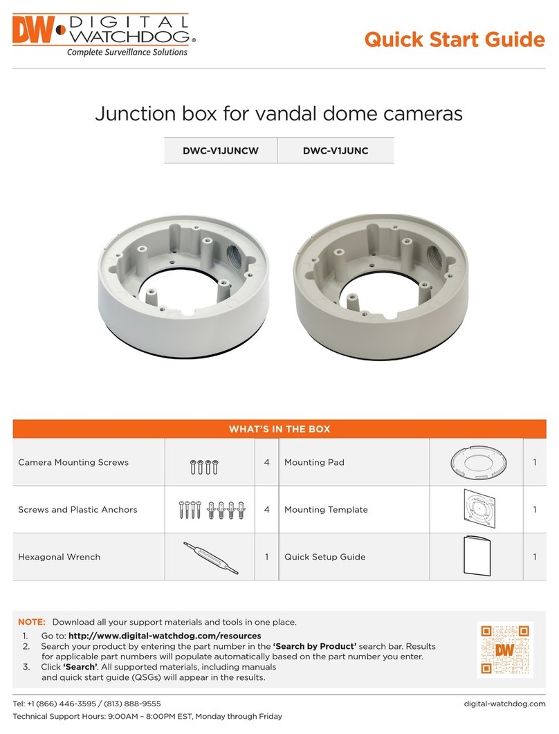
Digital Watchdog DWC-V1JUNCW User manual
Digital Watchdog
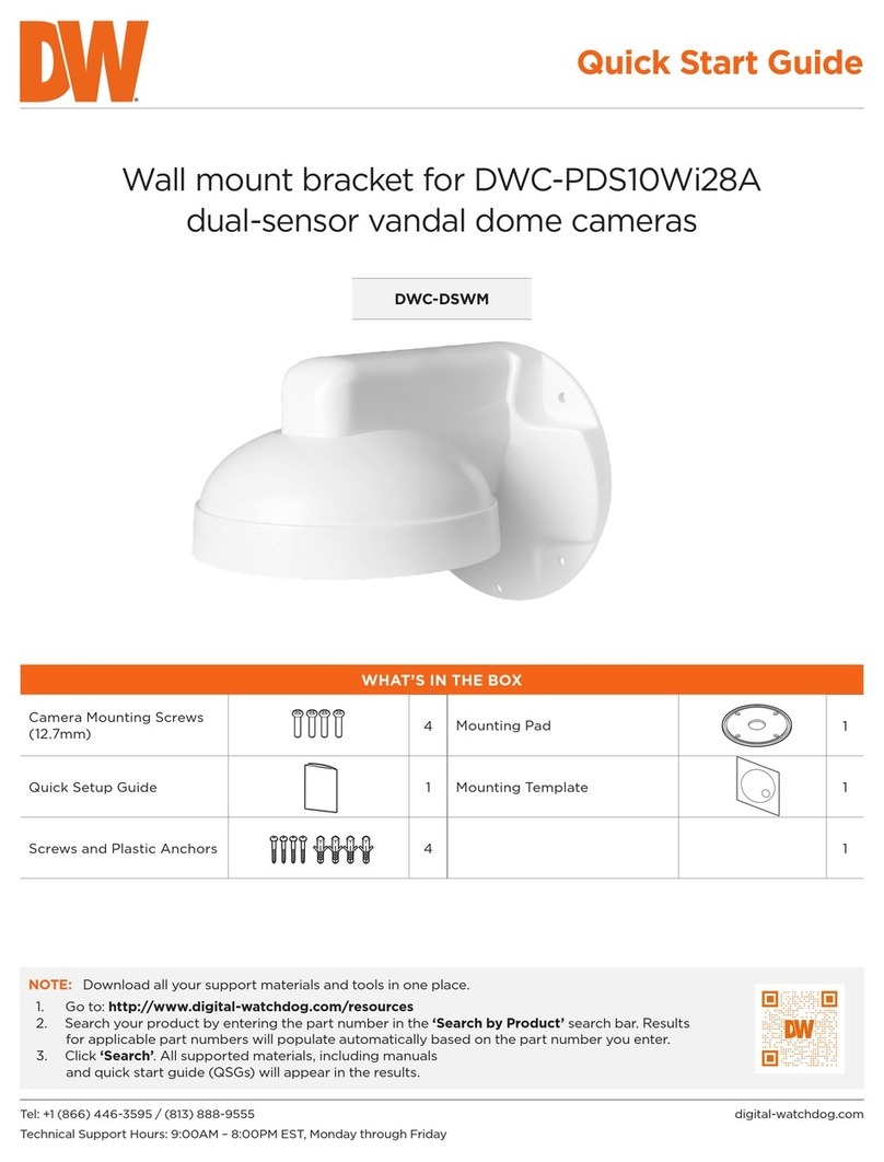
Digital Watchdog DWC-DSWM User manual
Digital Watchdog
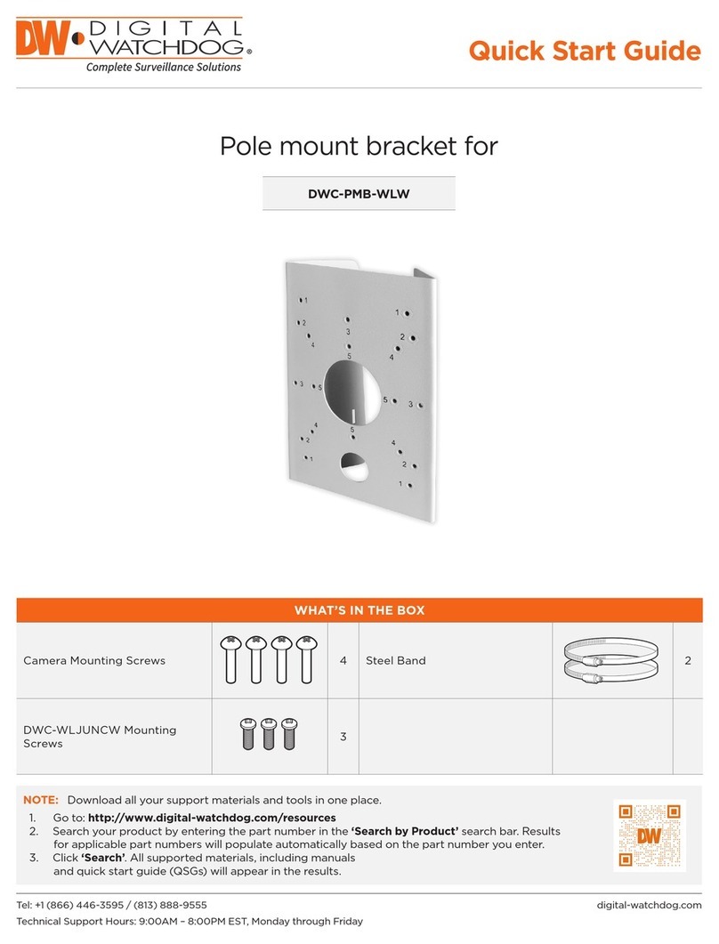
Digital Watchdog DWC-PMB-WLW User manual
Digital Watchdog
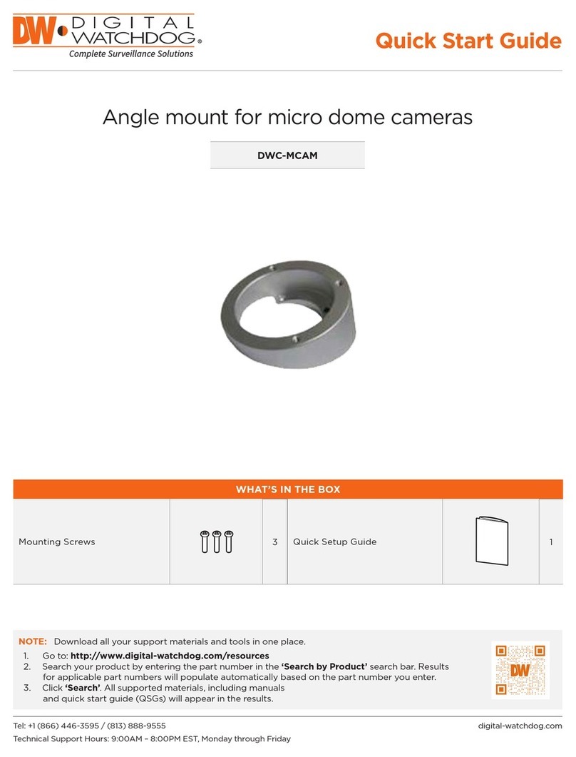
Digital Watchdog DWC-MCAM User manual
Digital Watchdog
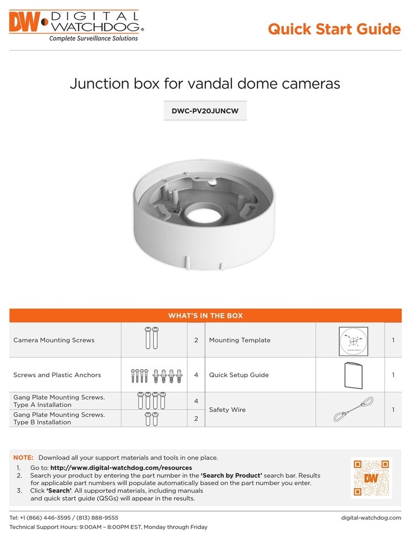
Digital Watchdog DWC-PV20JUNCW User manual
Digital Watchdog
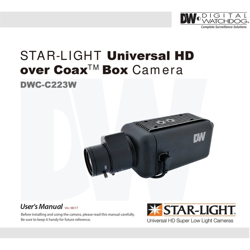
Digital Watchdog DWC-C223W User manual
Digital Watchdog
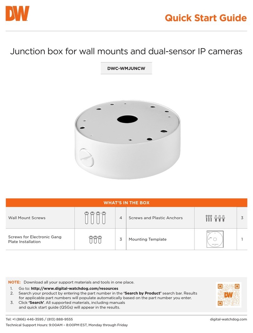
Digital Watchdog DWC-WMJUNCW User manual
Digital Watchdog
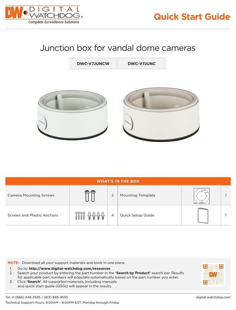
Digital Watchdog DWC-V7JUNCW User manual
Digital Watchdog
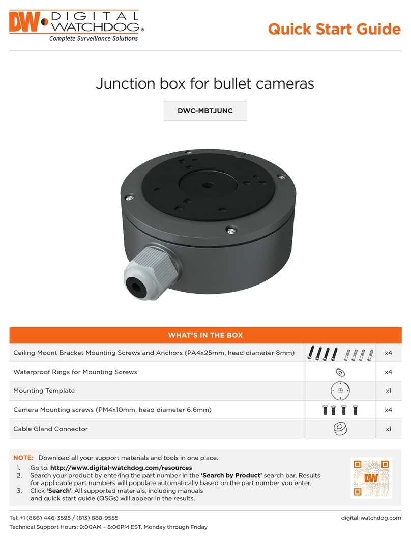
Digital Watchdog DWC-MBTJUNC User manual
Popular Camera Accessories manuals by other brands

Viltrox
Viltrox EF-NEX Mount instructions

Calumet
Calumet 7100 Series CK7114 operating instructions

Ropox
Ropox 4Single Series User manual and installation instructions

Cambo
Cambo Wide DS Digital Series Main operating instructions

Samsung
Samsung SHG-120 Specification sheet

Ryobi
Ryobi BPL-1820 Owner's operating manual
