- 2 -
6200 Series
Art. 6296 - Installation instructions
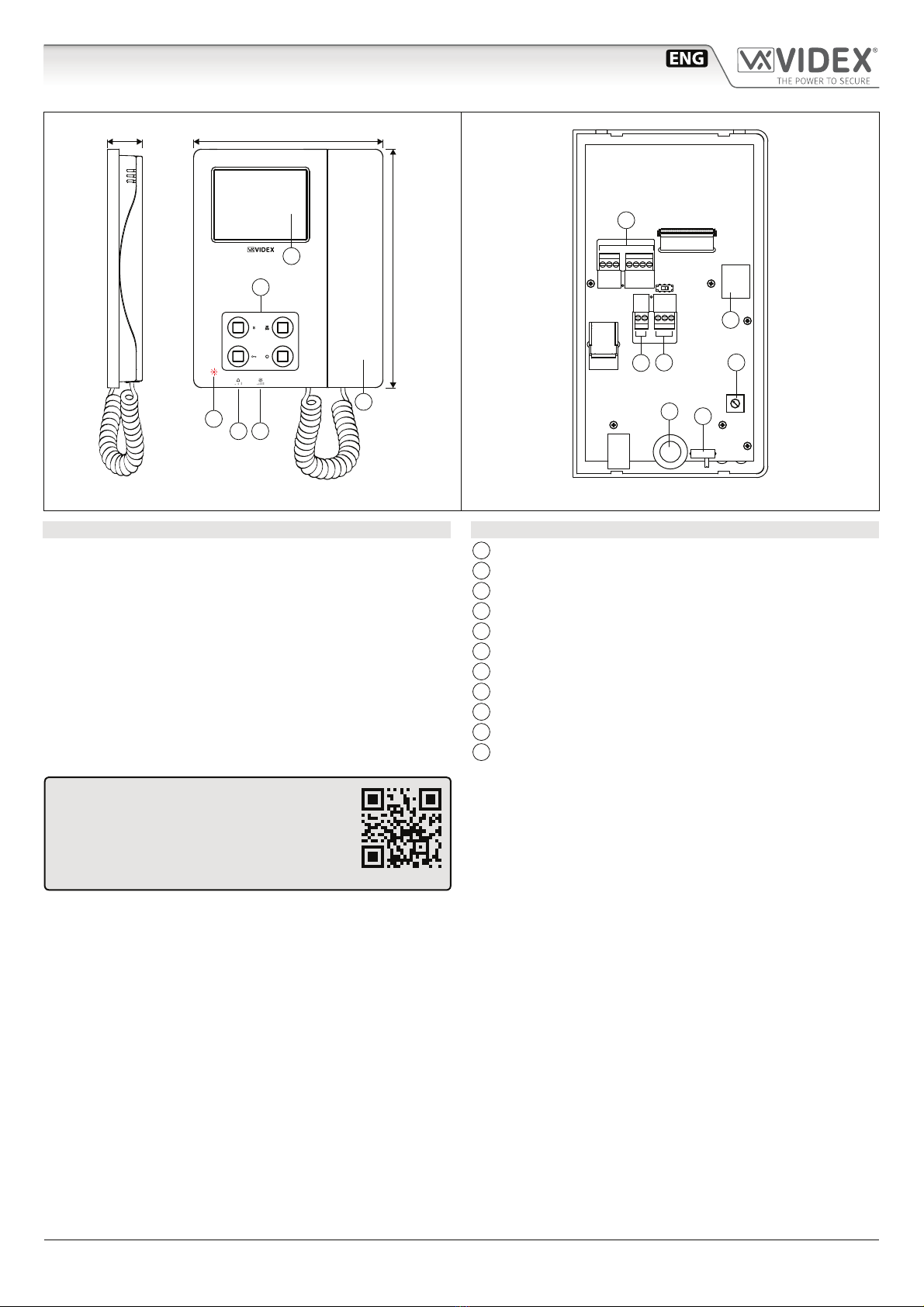
PUSH BUTTONS
The button operation depends on the conguration carried out through the conguration software forVIDEX IP system“Videx IPWizard”.
Default button functions can be changed, the function of the button can be dierent depending on the current state of the videophone.
• “In Stand- by”when the system is not in use.
• “Ringing”during an incoming call.
• “In Conversation”during a conversation between the resident and the visitor.
Service push button
It is possible to set two dierent operating modes according to the system status: “In Stand-by”,“In Conversation”.
• “In Stand-by”the button can be congured to trigger a specic relay of a specic door panel.
• “In Conversation”the button can be congured to trigger a specic relay of a specic door panel or the rst or second
relay of the active door panel.
As default, this button is disabled in both operating states.
During the conversation, to take a picture of the current video, keep pressed until the display doesn’t show the camera
icon with the date & time of the picture.
Privacy ON-OFF push button
It is possible to set two dierent operating modes according to the system status: “In Stand-by”,“In Conversation”.
• “In Stand-by” it can only be used as a “privacy on-o” button. Press to activate (privacy LED illuminates) or press to
deactivate (privacy LED goes o).
• “In Conversation”the button can be congured to trigger a specic relay of a specic door panel or the rst or second
relay of the active door panel.
As default, the privacy is set to “Innite”and the button is disabled for the“In Conversation”state.
The button operates also as video source switch, during the conversation, keep pressed until the video source switches from
the module built-in camera video signal to the external video source and viceversa.When the door panel is set for an external
video source, it is also possible to set the default video signal source (internal or external) transmitted during a call.
By pressing this button while the videophone is ringing, the call is rejected (the rejection is not recognized by the visitor).
Door open push button
It is possible to set one operating mode for both the statuses“Ringing”and“In Conversation”.
• “In Conversation”&“Ringing”the button can be congured to trigger a specic relay of a specic door panel or the rst
or second relay of the active door panel.
In Stand-by, when pressed, an intercommunicating call is started with the preferred videophone.
As default, the button activates the“relay 1”of the active door panel.
Camera recall push button
The operation of this button cannot be customised, it works as a camera recall button during Stand-by.
During a camera recall session, if the speech toward the door panel is disabled, to enable the speech, keep this button
pressed until the speech is enabled.
LEDS
Privacy on LED
It illuminates when the privacy service is enabled.
Service LED
It ashes showly if the gateway is not found when the
keep alive is set to“ping”.
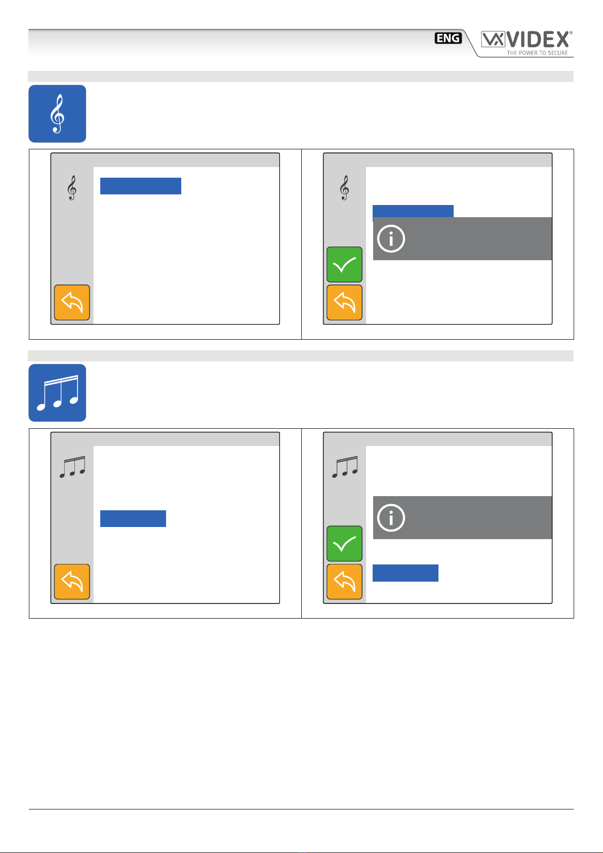
CONTROLS
Call tone volume control
3 level switch (it controls also the local bell volume).
Brightness control
Sliding wheel.
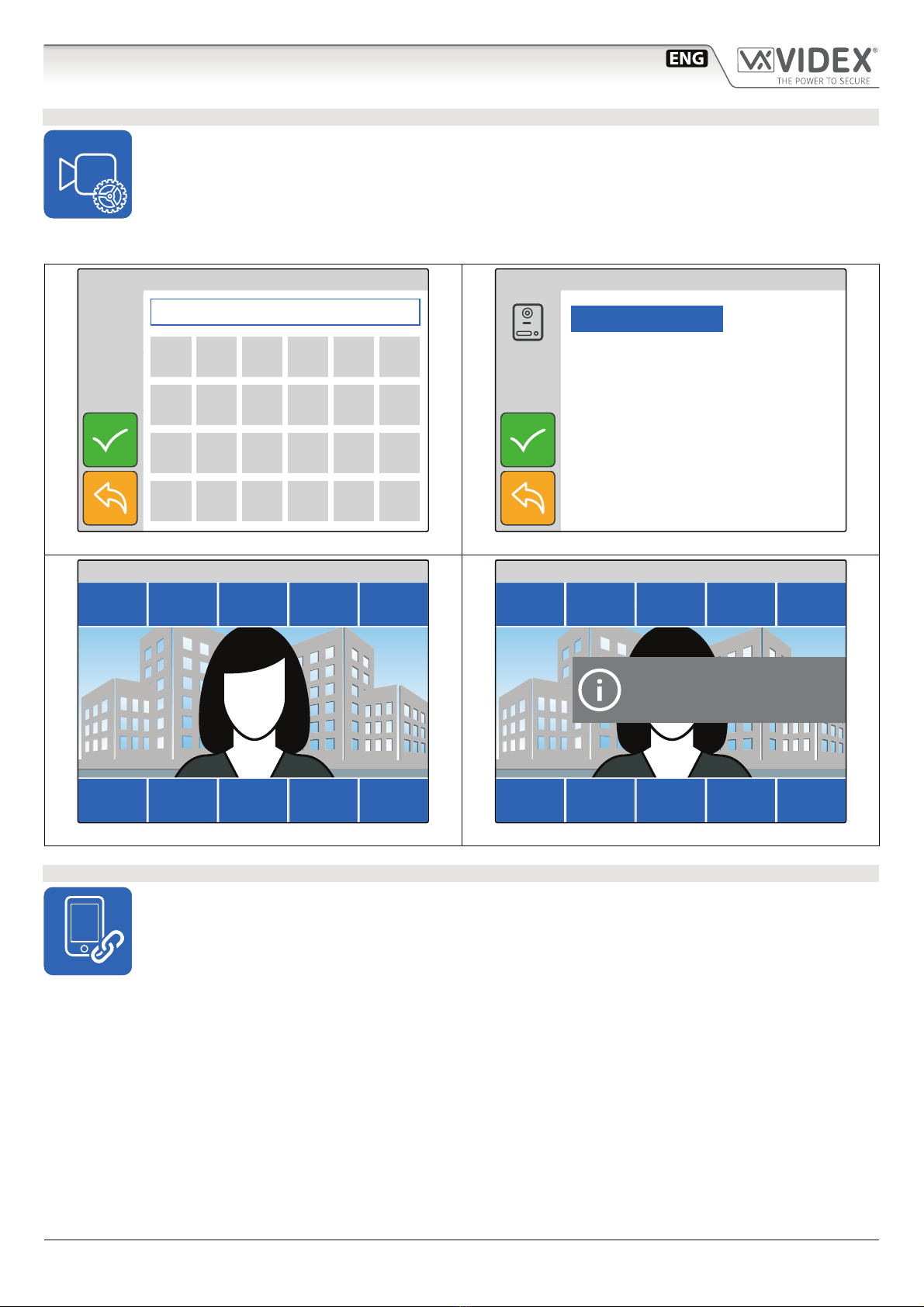
VIDEOPHONE INITIALISATION
If powering on the videophone (through a POE switch/router or
an external power supply unit) the display shows the message
“DEVICE NOT INITIALISED”(Fig. 3), use the conguration software
forVIDEX IP system (Videx IPWizard.exe) to set the device and the
system.
DEVICE NOT INITIALISED
Please, use Videx IP Wizard
to set the device
Fig. 3 Device not initialised
Art.6296 IP Videophone for VIDEX IP System