ALL : >B02
0001 : >B02
ALL : >9600bps
0001 : >9600bps
SET CAM PROTOCOL
>SET_PROTOCOL>
SET CAM PROTOCOL: Setup the Protocol for CAM. Each camera can be program with
different Protocol. After setting, press ENTER to save or CLR to exit the setting.
SET CAM PROTOCOL
>SET_BAUDRATE>
SET CAM BAUDRATE: Set up the Baud rate for CAM. Supported settings: 1200bps,
2400bps, 4800bps, 9600bps and 19200 bps. After setting, press ENTER to save or
CLR to exit the setting.
SET DVR CHANNEL: When multiple DVRs are used, the keyboard can map the DVR-
channel input to a certain PTZ's ID. Once the DVR's channel is changed, the PTZ which
responding to this channel will be selected automatically.
SET DVR:
>SET_CHANNEL>
ID:01 OUT:0001
IN:01 CAM:0001
DVR ID Monitor ID for output
DVR CH ID Camera ID
mapped to DVR CH ID
ALL : >9600bps
000 : >1 9600bps
SET MUX PROTOCOL
>ROBOT
SET DVR:
>SET_BAUDRATE>
SET DVR BAUTRATE: Setup the baud rate for DVR:
Supported: 1200bps,2400bps, 4800bps, 9600bps and 19200 bps
SET MUX PROTOCOL: Setup the Protocol for Multiplexer. Supporting: ROBOT, VC,
SONY, BOSCH and PELCO.
SET DVR PROTOCOL: Setup the DVR Protocol.
Supported: NVIDO, VC, DSCP, HIK, TUMIN, MITSU, DH and INTLX
ALL : >NVIDO
01 : >NVIDO
SET DVR:
>SET_PROTOCOL>
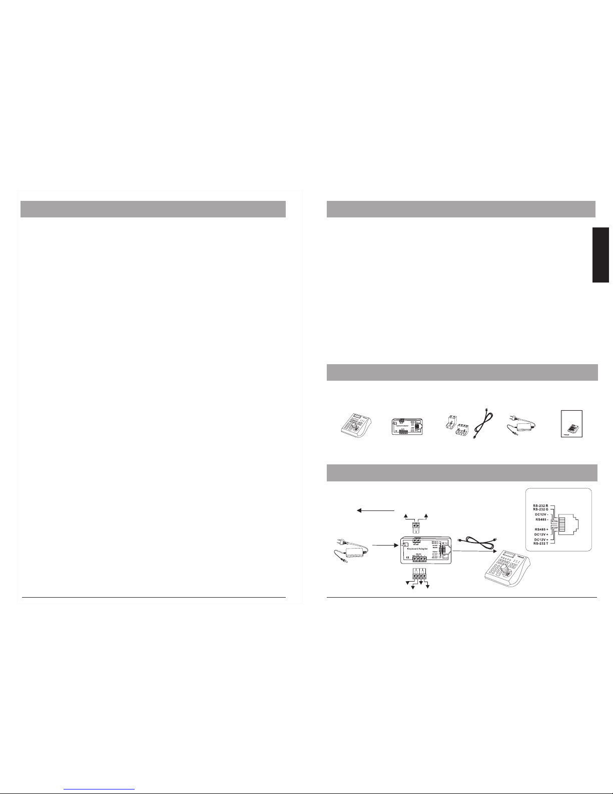
6. KEYBOARD SETUP
In order to get all advantages and functions, it is strongly recommended to
setup your keyboard before operation.
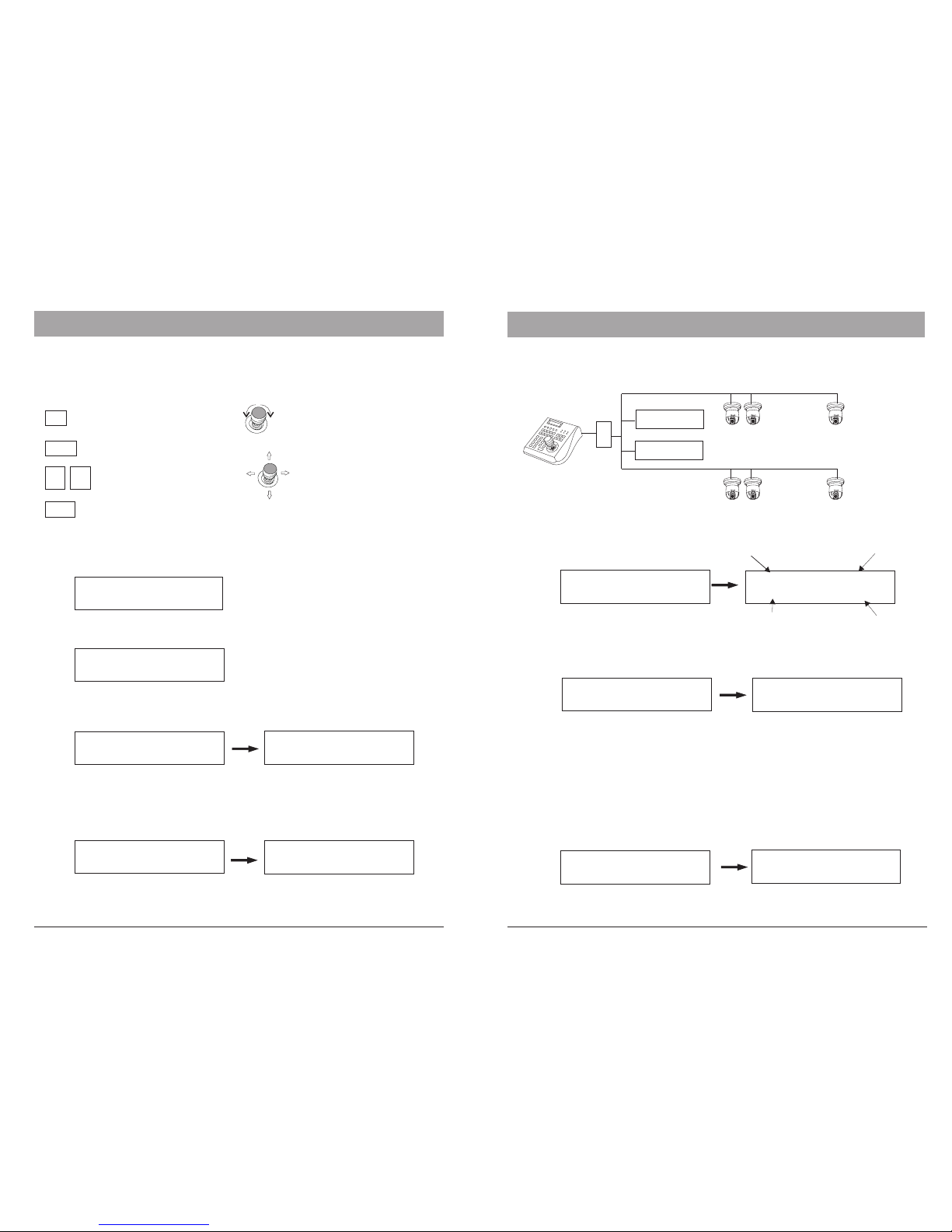
Navigation:
- Scroll the main menu
- Navigate the cursor between
the sub items
Move UP, DOWN, LEFT or
RIGHT.
CLR
ENTER
09
Return to the previous level
Confirmation or save setting
Digit input for changing
function value
change the value or options
by turning the control-stick to
the LEFT or RIGHT end
MENU
Back to Menu
ALL: Protocol setting for all DVR ID
01: individual setting for DVR ID 01
ALL: Baud rate setting for all DVR ID
01: individual setting for DVR ID 01
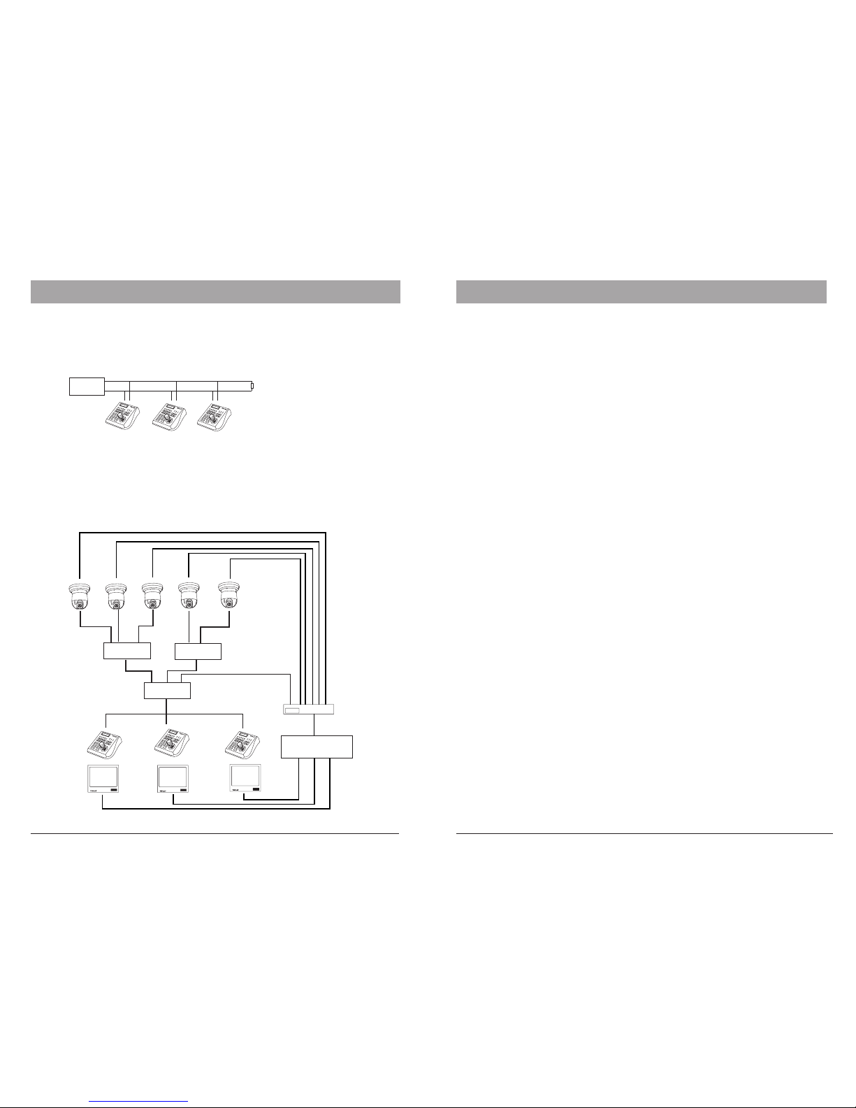
Example:
In DVR mode, when DVR2 is selected and input channel is switched to No. 2,
the keyboard will automatically set the current camera to ID 18, which is
physically connect to the 2nd input of the DVR.
KB3N
DVR 1
DVR 2
PTZ ID 17 to 32, DVR input 1-16
PTZ ID 1 to 16, DVR input 1-16
SET MTX BAUD RAT: .Set up the Baud rat for Matrix Supporting: 1200bps,2400bps,
4800bps, 9600bps and 19200 bps.Press ENTER to save or CLR to exit
SET MTX BAUD RAT
>9600bps
5 6
ALL: Protocol setting for all CAMERA ID
01: individual setting for CAMERA ID 01
ALL: Protocol setting for all CAMERA ID
01: individual setting for CAMERA ID 01
6. KEYBOARD SETUP
Selectable Protocol (v.34):B01, B02, Pelco, Pelco-D, SonyD70(Visca), Intellix, VC, Panasonic,
Samsung, DM, Li-Lin, CBC, VCL