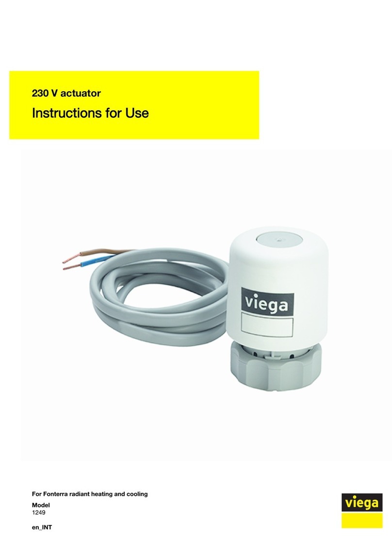
Viega Fonterra Smart Control User manual

Year built:
from 11/2015
en_INT
Fonterra Smart Control
Instructions for Use

Fonterra Smart Control 2 from 115

Table of contents
1About these instructions for use 5
1.1 Target groups 5
1.2 Labelling of notes 5
1.3 Acronyms 6
1.4 About this translated version 6
2Product information 7
2.1 Standards and regulations 7
2.2 Safety advice 8
2.3 Intended use 8
2.4 Regulations / certificates 8
2.5 Product description 9
2.5.1 Functions and characteristics 9
2.5.2 Overview and description of component 10
2.5.3 Accessories 17
2.6 Technical data 23
2.6.1 Electronic system 23
2.6.2 Software / hardware 27
2.7 System requirements 27
2.7.1 Hardware 27
2.7.2 Software 28
2.8 Configuration levels 29
3Handling 31
3.1 Transport and storage 31
3.2 Assembly information 31
3.2.1 Preconditions for installation 31
3.2.2 Installation dimensions 32
3.3 Assembly 34
3.3.1 Assembly sequence 34
3.3.2 Mounting the temperature measuring points 34
3.3.3 Mounting the actuators 36
3.3.4 Mounting the basic unit 36
3.3.5 Mounting the actuator modules 43
3.3.6 Mounting the room thermostat 46
3.3.7 Mounting the radio amplifier 52
3.4 Commissioning 52
Table of contents
Fonterra Smart Control 3 from 115

3.4.1 Preconditions for commissioning 52
3.4.2 Configuration level 1 – Control via power level 54
3.4.3 Configuration level 2 – Control via room thermostat 55
3.4.4 Configuration level 3 – Operation of a base station in the
WLAN network 60
3.4.5 Configuration level 4 – Operating several base stations via
the Internet 65
3.4.6 Checking the functions 78
3.4.7 Resetting the factory settings – Reset 79
3.4.8 Operating conditions 81
3.5 Control 83
3.5.1 Room thermostat 83
3.5.2 Operating software 84
3.6 Faults 106
3.6.1 Fault alarms 106
3.7 Care and maintenance 109
3.7.1 Maintenance 109
3.7.2 Care 109
3.7.3 Replacing components 110
3.8 Disposal 115
Table of contents
Fonterra Smart Control 4 from 115

1 About these instructions for use
Trade mark rights exist for this document; for further information, go to
viega.com/legal.
1.1 Target groups
The information in this instruction manual is directed at the following
groups of people:
nHeating and sanitary professionals and trained personnel
nQualified electricians
nOperators
nConsumers
Individuals without the abovementioned training or qualification are not
permitted to mount, install and, if required, maintain this product. This
restriction does not extend to possible operating instructions.
The installation of Viega products must take place in accordance with
the general rules of engineering and the Viega instructions for use.
This manual must be handed over to the operator or user after the
assembly and commissioning of the product.
1.2 Labelling of notes
Warning and advisory texts are set aside from the remainder of the text
and are labelled with the relevant pictographs.
DANGER!
This symbol warns of possible life-threatening injury.
WARNING!
This symbol warns of possible serious injury.
CAUTION!
This symbol warns of possible injury.
NOTICE!
This symbol warns of possible damage to property.
About these instructions for use
Fonterra Smart Control 5 from 115

This symbol gives additional information and hints.
1.3 Acronyms
This documentation uses the following abbreviations:
WM Wall mounting
CC Concealed mounting
1.4 About this translated version
This instruction for use contains important information about the choice
of product or system, assembly and commissioning as well as intended
use and, if required, maintenance measures. The information about the
products, their properties and application technology are based on the
current standards in Europe (e. g. EN) and/or in Germany
(e. g. DIN/DVGW).
Some passages in the text may refer to technical codes in Europe/
Germany. These should serve as recommendations in the absence of
corresponding national regulations. The relevant national laws, stand‐
ards, regulations, directives and other technical provisions take priority
over the German/European directives specified in this manual: The
information herein is not binding for other countries and regions; as said
above, they should be understood as a recommendation.
About these instructions for use
Fonterra Smart Control 6 from 115

2 Product information
2.1 Standards and regulations
The following standards and regulations apply to Germany / Europe and
are provided as a support feature.
Regulations from section: Regulations / Certificates
Scope / Notice Regulations applicable in Ger‐
many
CE conformity of the electrical
components
EN 60730-1
nPart 1 – General requirements
nPart 2-9: Special requirements
in temperature-dependant reg‐
ulation and control systems
CE conformity of the electrical
components
EN 300220-1
Regulation on energy-saving heat
insulation and energy-saving
installation engineering
Energieeinsparverordnung (EnEV)
Household and similar electrical
appliances – Safety
(SRD) IEC 60335-1
Information technology equipment
– Radio disturbance characteris‐
tics
EN 55022
Regulations from section: Extension level 1 – Control via power level
Scope / Notice Regulations applicable in Ger‐
many
Control mode for secondary
rooms or rooms < 6 m2
Energieeinsparverordnung (EnEV)
Regulations from section: Disposal
Scope / Notice Regulations
Disposal of electronic compo‐
nents
WEEE-Richtlinie 2012/19/EU
Product information
Fonterra Smart Control 7 from 115

2.2 Safety advice
DANGER!
Danger due to electrical current
An electric shock can lead to burns and serious injury and
even death.
– Work on the electrics may only be carried out by trained
electricians.
– Switch off the mains voltage before carrying out work on
electrical parts.
NOTICE!
All cable connections must be made via plug connections,
their form should make them non-interchangeable.
The connection cables may not be extended.
The total length of the connection cable must not exceed
10 m.
2.3 Intended use
Fonterra Smart Control is an electronic single room regulation for
radiant heating and cooling systems with one or several manifolds. In
connection with radiant heating and cooling systems, the system can be
used within a control range of 5–30 °C also for cooling purposes. The
function is guaranteed for the combination with Fonterra manifolds
DN25.
Manifolds by other manufacturers are compatible if they comply with
the following specification:
nThreaded connection with euro cone and valve inserts –
M30 x 1.5 mm
nValve inserts – stroke 3.2 mm / resulting dimension 11.8 mm
nManifold outlets – minimum distance 45 mm
Use with electronic components by other manufacturers is not per‐
mitted.
2.4 Regulations / certificates
All components have a CE mark and comply with the applicable regula‐
tions, see
Ä
„Regulations from section: Regulations / Certificates“
on page 7.
Product information
Fonterra Smart Control 8 from 115

2.5 Product description
2.5.1 Functions and characteristics
Fonterra Smart Control is an electronic single room regulation for
radiant heating and cooling systems with one or several manifolds in a
control range of 5-30 °C.
The room temperatures can be set individually for each heating circuit
with power levels, via room thermostat control, or centrally via end
devices. Access to the parameters of individual casing units and to the
control of entire buildings via building master control systems is carried
out via password-protected WLAN or Internet connections.
The temperature data of the room thermostats, the flow sensor and the
return flow sensors are evaluated by measurement and used for the
individual temperature control of each heating circuit.
Benefits of the system:
nManual hydraulic calibration is no longer necessary and is replaced
by permanent hydraulic calibration via the system.
nThe control system compensates external interferences:
– Different pipe sizes, installation distances, heating circuit lengths
– Different screed heights, floor coverings, areas covered by rugs
or furniture etc.
– Fluctuating supply temperatures
– Outdoor temperatures, external heat sources
In keeping with the on-site requirements, Fonterra Smart Control can be
operated in four configuration levels:
nConfiguration level 1: Control via power level
The base station controls the actuators via a power level – no room
thermostat is installed.
nConfiguration level 2: Control via room thermostat
The base station controls the actuators via calibration of the target/
actual value of the room temperature with the room thermostat.
nConfiguration level 3: Operation of a base station in a WLAN network
Access to all system settings with direct connection to the WLAN
module.
nConfiguration level 4: Operation of several base stations via Internet
World-wide password-protected access to the system settings via
the router in the home network.
Ä
Chapter 2.8 „Configuration levels“ on page 29
Configuration levels
Product information
Fonterra Smart Control 9 from 115

nSimplified commissioning without manual hydraulic calibration.
nEnergy saving thanks to an intelligent heating concept.
nGeneration of individual heating profiles with
6 switching points per day for each room.
nPassword-protected configuration of individual utilisation units.
nUser-friendly representation and access to all functions via screen
menus.
nComfort functions:
– Limitation of the room temperatures that can be set at the room
thermostats
– Absence function with saving mode
– Protection from cool-down of the floor, also when the room is
heated by external heat sources such as insolation, open fire‐
places, etc.
– Priorisation of individual rooms in heat-up phases
– Long-term analysis of the supply temperatures – for the optimi‐
sation of the system settings
– Fault diagnosis system
2.5.2 Overview and description of component
Depending on the selected configuration level and the structural situa‐
tion, the parts must be ordered separately.
Ä
Chapter 2.8 „Configuration levels“ on page 29.
AKTOR
VL-TEMP
TAUP.
RS-232
RESET
1
2
3
4
5
6
B
C
7
D
E
A
Fig. 1: Component overview
1 - Radio amplifier / room thermostat
2 - Room thermostat / radio amplifier
3 - Basic unit
4 - WLAN module
5 - Actuator
6 - Actuator modules
7 - Flow sensor
A - Return flow beam
B - Supply flow beam
Features
Component overview
Product information
Fonterra Smart Control 10 from 115

C - Heating circuit connections supply line
D - Flow quantity gauge
E - Heating circuit connections return flow
Model 1250.5
Display white, article 734 527
Display black, article 734 022
Setting of desired room temperature and indication of the current room
temperature, target temperature, operating mode, fault.
Scope of delivery
1
2
3
4
5
Fig. 2: Room thermostat – front
1 - Metal plate
2 - Mounting frame
3 - Display
4 - Batteries AA
5 - Dowels (Ø 5 mm) / screws
Raumthermostat
ON 222640
RT C0A44CF7
1
2
3
1
4
Fig. 3: Room thermostat - casing rear
1 - Battery compartments
2 - Plug socket for window contact
3 - Plug socket 6.5 V for power pack connection
4 - Cable routing
Mounting
Ä
Chapter 3.3.6 „Mounting the room thermostat“ on page 46.
Room thermostat
Product information
Fonterra Smart Control 11 from 115

Model 1250
Functions of the base station:
nData collection, exchange, storage for all components involved in the
system.
nRadio-controlled communication at frequency 868 MHz with room
thermostats and radio amplifiers.
nCommunication in WLAN / Internet with end devices – laptops, tab‐
lets, smartphones, etc.
nEvaluation of the temperatures of supply line and return flow sen‐
sors, of the desired temperature set by the user (target value) and
actual room temperature (actual value).
nControl of the actuators.
Scope of delivery
AKTOR
VL-TEMP
TAUP.
RS-232
RESET
1
14 13 12 11 10 9 8 7
2 3 4 5 6
Fig. 5: Basic unit
1 - Power pack
2 - Socket connection cable for actuator module
3 - Socket flow sensor
4 - Socket dewpoint sensor
5 - Socket WLAN module
6 - Reserve socket
7 - Button cell
8 - Reset button
9 - Casing lock
10 - Button "ok"
11 - Button "connect"
12 - LED "connect"
13 - LED "status"
14 - casing upper part
The scope of delivery furthermore includes:
nFlow sensor
nConnection cable for actuator modules
nHeat conduction pad
nButton cell
nfixing material
Mounting
Ä
Chapter 3.3.4 „Mounting the basic unit“ on page 36.
Basic unit
Product information
Fonterra Smart Control 13 from 115

Model 1250.10
The temperature measuring point receives the actuator module and is
mounted to the heating circuit return at the manifold bar.
Scope of delivery
1
2
3
Fig. 6: Temperature measuring point
1 - Connection screw fitting for return flow beam (euro cone)
2 - Immersion sleeve as contact point for the temperature sensor
3 - Connection for heating pipe (euro cone)
Mounting
Ä
Chapter 3.3.2 „Mounting the temperature measuring
points“ on page 34.
Temperature measuring point
Product information
Fonterra Smart Control 14 from 115

Model 1250.11
The actuator module is plugged onto the temperature measuring point.
Cable connections have been installed between the assigned actuator,
the actuator modules of the other heating circuits, and the base station.
The actuator module on the one hand transmits the return temperature
to the base station and on the other hand the control signal to the
actuator.
Scope of delivery
1
2
3
Fig. 7: Actuator module
1 - LED
2 - Button
3 - Connection cable for actuator module / base station
1
2
3
Fig. 8: Actuator module rear side
1 - Socket for adjacent actuator module
2 - Socket actuator
3 - Socket for connection cable to the base station or to the adjacent
actuator module
Mounting
Ä
Chapter 3.3.5 „Mounting the actuator modules“
on page 43.
Actuator module
Product information
Fonterra Smart Control 15 from 115

Model 1250.15
The actuator controls the flow volume of the heating circuit. The respec‐
tive actuation signals are transmitted by the base station via cable con‐
nection.
Scope of delivery:
1
2
3
4
Fig. 9: Actuator
1 - Display of valve setting
2 - Casing with electronic unit
3 - Plug for actuator module
4 - Connection screw fitting return flow beam
Mounting
Ä
Chapter 3.3.3 „Mounting the actuators“ on page 36.
Model 1250.16
The WLAN module establishes the contact of the base station to the
end devices. It is connected to the base station via cable.
Scope of delivery:
1
2
Fig. 10: WLAN module
1 - Transmission unit
2 - plug for the basic unit
Mounting
Ä
„Mounting the WLAN module“ on page 41.
Actuator
WLAN module
Product information
Fonterra Smart Control 16 from 115

Model 1250.20
Display white, article 736453
Display black, article 734480
Room thermostats communicate with the base station over the radio
frequency 868 MHz. If the radio signal becomes too weak with
increasing distance between devices, one or a maximum of two radio
amplifiers can be installed in the radio link to stabilize the signal. At the
same time, a maximum of two radio amplifiers can be logged in "in par‐
allel" to a base station.
Radio amplifiers require a 230 V mains connection.
Scope of delivery:
1
2
3
4
Fig. 11: Radio amplifier
1 - Metal plate
2 - Mounting frame
3 - Display
4 - Dowels (Ø 5 mm) / screws
1
2
3
Fig. 12: Casing rear side
1 - Power pack connection 6.5 V
2 - Latch at the mounting frame
3 - Cable routing
For information regarding mounting, see
Ä
Chapter 3.3.7 „Mounting the
radio amplifier“ on page 52.
Radio amplifier
Product information
Fonterra Smart Control 18 from 115

Model 2245.63
The concealed power pack is suitable for installation in concealed
sockets (Ø 60 mm) and is used for the power supply to room thermo‐
stats and radio amplifiers. The room thermostats and radio amplifiers
are fastened on the concealed socket with two screws.
Scope of delivery
1
2
3
Fig. 13: Concealed power pack
1 - Power pack
2 - Device connection with plug for 6.5 V DC
3 - Mains connection with Wago terminals for 230 V
For information regarding mounting, see
Ä
„Mounting the room thermo‐
stat on a concealed socket“ on page 49.
Model 1250.22
The Smart Control power pack supplies power to room thermostats and
radio amplifiers. The 230 V mains connection is provided via a socket
with an on-the-wall cable for the 6.5 V DC device connection.
The cable length is 1000 mm.
Fig. 14: Smart Control power pack
For information regarding mounting, see
Ä
„Mounting the room thermo‐
stat to the wall“ on page 47.
Concealed power pack
Smart Control power pack
Product information
Fonterra Smart Control 19 from 115

Model 1250.25
The dewpoint sensor is required if the radiant heating and cooling
system is used for cooling purposes. When critical humidity values are
reached in the manifold cabinet, the system will switch the cooling
power off to avoid the formation of condensate at the components. The
dewpoint sensor is connected with the base station via a connection
cable.
The cable length is 800 mm.
Scope of delivery:
1
2
Fig. 15: dewpoint sensor
1 - dewpoint sensor
2 - plug for the basic unit
For information regarding mounting, see
Ä
„Mounting the dewpoint
sensor“ on page 40.
dewpoint sensor
Product information
Fonterra Smart Control 20 from 115
This manual suits for next models
12
Table of contents
Other Viega Controllers manuals