ST STM32W-SK User manual

May 2012 Doc ID 16999 Rev 5 1/37
UM0894
User manual
STM32W-SK and STM32W-EXT starter and extension kits
for STM32W108xx microcontrollers
Introduction
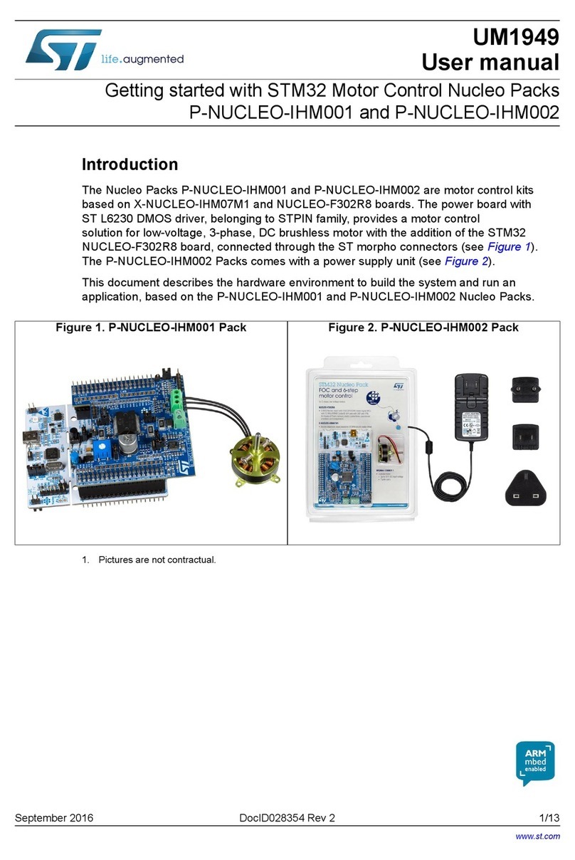
The STM32W-SK and STM32W-EXT starter and extension kits are easy to use tools for the
STM32W108xx microcontrollers. This family of microcontrollers integrates a 32-bit ARM®
Cortex™-M3 microprocessor and a 2.4 GHz, IEEE 802.15.4-compliant transceiver. The kits
demonstrate how effectively the STM32W108xx can be used in real IEEE 802.15.4
applications. They are suitable for different types of wireless network scenarios such as:
●Remote control and target networks (based on the ZigBee RF4CE protocol stack) used
for driving consumer devices such as TVs, set-top boxes, etc.
●Point to point networks (based on a Simplified MAC library) used to address a basic
IEEE 802.15.4 communication. This configuration enables customers to develop any
protocol stack of their choice.
The STM32W108xx kits provide demonstration applications and documentation which serve
as a reference for creating your own applications and re-programming the STM32W108xx
microcontroller. You can run the STM32W108xx kits in several ways (remote control/target
and point-to-point applications), using the dedicated software libraries (ZigBee RF4CE, and
Simplified MAC), as well as a third-party IDE and C compiler (IAR).
Moreover, the STM32W108xx kits provide a set of HAL APIs which allow you to use the kit
platform capabilities such as LEDs and serial communication channels (virtual COM
through USB).
In this manual, you can find information about:
●The STM32W108xx kits components
●How to install the related hardware, software and documentation trees
●How to run the preprogrammed demonstration applications.
Note: 1 The term “application board” refers to the MB851 and MB954 platforms.
2 For more information, visit the STM32W 32-bit RF microcontroller webpages at
www.st.com/stm32w
This web page provides full access to all the STM32W108xx resources (kits, software
packages and documents).
Table 1 lists the microcontrollers and evaluation tools concerned by this user manual.
Table 1. Applicable products and tools
Type Applicable products
Microcontrollers STM32W High-performance, IEEE 802.15.4 wireless systems-on-chip with
embedded Flash memory
Evaluation tools STM32W-SK and STM32W-EXT starter and extension kits
www.st.com
www.BDTIC.com/ST

Contents UM0894
2/37 Doc ID 16999 Rev 5
Contents
1 Getting started . . . . . . . . . . . . . . . . . . . . . . . . . . . . . . . . . . . . . . . . . . . . . . 6
1.1 Kit description . . . . . . . . . . . . . . . . . . . . . . . . . . . . . . . . . . . . . . . . . . . . . . . 6
1.1.1 Hardware . . . . . . . . . . . . . . . . . . . . . . . . . . . . . . . . . . . . . . . . . . . . . . . . . 6
1.2 MB850 hardware description . . . . . . . . . . . . . . . . . . . . . . . . . . . . . . . . . . . 7
1.2.1 MB850 resources . . . . . . . . . . . . . . . . . . . . . . . . . . . . . . . . . . . . . . . . . . . 7
1.2.2 MB850 connectors . . . . . . . . . . . . . . . . . . . . . . . . . . . . . . . . . . . . . . . . . . 7
1.2.3 MB850 connectors: JP1 pins . . . . . . . . . . . . . . . . . . . . . . . . . . . . . . . . . . 8
1.2.4 MB850 connectors: JP2 pins . . . . . . . . . . . . . . . . . . . . . . . . . . . . . . . . . . 8
1.2.5 MB850 jumper configuration . . . . . . . . . . . . . . . . . . . . . . . . . . . . . . . . . . 8
1.2.6 MB850 PC interface chip . . . . . . . . . . . . . . . . . . . . . . . . . . . . . . . . . . . . . 9
1.2.7 MB850 battery holder . . . . . . . . . . . . . . . . . . . . . . . . . . . . . . . . . . . . . . . 9
1.3 MB851 hardware description . . . . . . . . . . . . . . . . . . . . . . . . . . . . . . . . . . . 9
1.3.1 MB851 resources . . . . . . . . . . . . . . . . . . . . . . . . . . . . . . . . . . . . . . . . . . . 9
1.3.2 MB851 connectors . . . . . . . . . . . . . . . . . . . . . . . . . . . . . . . . . . . . . . . . . . 9
1.3.3 MB851 connectors: P1 pins . . . . . . . . . . . . . . . . . . . . . . . . . . . . . . . . . . 10
1.3.4 MB851 connectors: P4 pins . . . . . . . . . . . . . . . . . . . . . . . . . . . . . . . . . . 11
1.3.5 MB851 jumper configuration . . . . . . . . . . . . . . . . . . . . . . . . . . . . . . . . . 11
1.3.6 MB851 PC interface chip . . . . . . . . . . . . . . . . . . . . . . . . . . . . . . . . . . . . 12
1.3.7 MB851 battery holder . . . . . . . . . . . . . . . . . . . . . . . . . . . . . . . . . . . . . . 12
1.4 MB954 hardware description . . . . . . . . . . . . . . . . . . . . . . . . . . . . . . . . . . 12
1.4.1 MB954 resources . . . . . . . . . . . . . . . . . . . . . . . . . . . . . . . . . . . . . . . . . . 12
1.4.2 MB954 connectors . . . . . . . . . . . . . . . . . . . . . . . . . . . . . . . . . . . . . . . . . 13
1.4.3 MB954 connectors: P1 pins . . . . . . . . . . . . . . . . . . . . . . . . . . . . . . . . . . 13
1.4.4 MB954 connectors: P4 pins . . . . . . . . . . . . . . . . . . . . . . . . . . . . . . . . . . 14
1.4.5 MB954 jumper configuration . . . . . . . . . . . . . . . . . . . . . . . . . . . . . . . . . 14
1.4.6 MB954 PC interface chip . . . . . . . . . . . . . . . . . . . . . . . . . . . . . . . . . . . . 15
1.4.7 MB954 battery holder . . . . . . . . . . . . . . . . . . . . . . . . . . . . . . . . . . . . . . 15
1.5 Software . . . . . . . . . . . . . . . . . . . . . . . . . . . . . . . . . . . . . . . . . . . . . . . . . . 15
1.6 Documentation . . . . . . . . . . . . . . . . . . . . . . . . . . . . . . . . . . . . . . . . . . . . . 15
1.7 Software libraries and demonstration applications . . . . . . . . . . . . . . . . . . 16
1.8 Kit setup . . . . . . . . . . . . . . . . . . . . . . . . . . . . . . . . . . . . . . . . . . . . . . . . . . 16
1.8.1 Powering on the boards . . . . . . . . . . . . . . . . . . . . . . . . . . . . . . . . . . . . . 16
1.8.2 Installing drivers for USB virtual COM . . . . . . . . . . . . . . . . . . . . . . . . . . 16

www.BDTIC.com/ST

UM0894 Contents
Doc ID 16999 Rev 5 3/37
1.8.3 Setting up the application serial communication channel . . . . . . . . . . . 17
2 Running the STM32W108xx kits . . . . . . . . . . . . . . . . . . . . . . . . . . . . . . 18
2.1 Installing the STM32W108xx kit software tree . . . . . . . . . . . . . . . . . . . . . 18
2.2 Remote control and virtual TV (based on RF4CE library) . . . . . . . . . . . . 18
2.2.1 Run the remote control (RC) and virtual TV applications . . . . . . . . . . . 18
2.2.2 Use the remote control (RC) and virtual TV applications . . . . . . . . . . . . 20
2.3 Basic star network (based on Simple MAC library) . . . . . . . . . . . . . . . . . 20
2.3.1 Run preloaded sample appl. on STM32-Primer2, MB850 platforms . . . 20
2.3.2 Run the prebuilt sample planet application on the application board . . . 21
2.3.3 Set up a star network . . . . . . . . . . . . . . . . . . . . . . . . . . . . . . . . . . . . . . . 21
3 STM32W108xx kits utilities and software tools . . . . . . . . . . . . . . . . . . 23
3.1 stm32w_flasher utility . . . . . . . . . . . . . . . . . . . . . . . . . . . . . . . . . . . . . . . . 23
3.2 Network analyzer . . . . . . . . . . . . . . . . . . . . . . . . . . . . . . . . . . . . . . . . . . . 23
3.2.1 Perytons . . . . . . . . . . . . . . . . . . . . . . . . . . . . . . . . . . . . . . . . . . . . . . . . . 23
3.3 IAR Embedded Workbench® for ARM . . . . . . . . . . . . . . . . . . . . . . . . . . . 24
4 List of acronyms . . . . . . . . . . . . . . . . . . . . . . . . . . . . . . . . . . . . . . . . . . . 25
5 Available board schematics . . . . . . . . . . . . . . . . . . . . . . . . . . . . . . . . . . 26
6 Revision history . . . . . . . . . . . . . . . . . . . . . . . . . . . . . . . . . . . . . . . . . . . 36
www.BDTIC.com/ST

List of tables UM0894
4/37 Doc ID 16999 Rev 5
List of tables
Table 1. Applicable products and tools. . . . . . . . . . . . . . . . . . . . . . . . . . . . . . . . . . . . . . . . . . . . . . . . 1
Table 2. MB850 connectors . . . . . . . . . . . . . . . . . . . . . . . . . . . . . . . . . . . . . . . . . . . . . . . . . . . . . . . . 7
Table 3. MB850 connectors: JP1 pins . . . . . . . . . . . . . . . . . . . . . . . . . . . . . . . . . . . . . . . . . . . . . . . . 8
Table 4. MB850 connectors: JP2 pins . . . . . . . . . . . . . . . . . . . . . . . . . . . . . . . . . . . . . . . . . . . . . . . . 8
Table 5. MB851 resources . . . . . . . . . . . . . . . . . . . . . . . . . . . . . . . . . . . . . . . . . . . . . . . . . . . . . . . . . 9
Table 6. MB851 connectors . . . . . . . . . . . . . . . . . . . . . . . . . . . . . . . . . . . . . . . . . . . . . . . . . . . . . . . . 9
Table 7. MB851 connectors: P1 pins . . . . . . . . . . . . . . . . . . . . . . . . . . . . . . . . . . . . . . . . . . . . . . . . 10
Table 8. MB851 connectors: P4 pins . . . . . . . . . . . . . . . . . . . . . . . . . . . . . . . . . . . . . . . . . . . . . . . . 11
Table 9. MB851 jumper configuration. . . . . . . . . . . . . . . . . . . . . . . . . . . . . . . . . . . . . . . . . . . . . . . . 11
Table 10. MB851 PC Interface chip . . . . . . . . . . . . . . . . . . . . . . . . . . . . . . . . . . . . . . . . . . . . . . . . . . 12
Table 11. MB851 battery holder . . . . . . . . . . . . . . . . . . . . . . . . . . . . . . . . . . . . . . . . . . . . . . . . . . . . . 12
Table 12. MB954 resources . . . . . . . . . . . . . . . . . . . . . . . . . . . . . . . . . . . . . . . . . . . . . . . . . . . . . . . . 12
Table 13. MB954 connectors . . . . . . . . . . . . . . . . . . . . . . . . . . . . . . . . . . . . . . . . . . . . . . . . . . . . . . . 13
Table 14. MB954 connectors: P1 pins . . . . . . . . . . . . . . . . . . . . . . . . . . . . . . . . . . . . . . . . . . . . . . . . 13
Table 15. MB954 connectors: P4 pins . . . . . . . . . . . . . . . . . . . . . . . . . . . . . . . . . . . . . . . . . . . . . . . . 14
Table 16. MB954 jumper configuration. . . . . . . . . . . . . . . . . . . . . . . . . . . . . . . . . . . . . . . . . . . . . . . . 14
Table 17. MB954 PC interface chip . . . . . . . . . . . . . . . . . . . . . . . . . . . . . . . . . . . . . . . . . . . . . . . . . . 15
Table 18. MB954 battery holder . . . . . . . . . . . . . . . . . . . . . . . . . . . . . . . . . . . . . . . . . . . . . . . . . . . . . 15
Table 19. Definition of LCD screen symbols (Simple MAC sample application). . . . . . . . . . . . . . . . . 22
Table 20. List of acronyms used in the document . . . . . . . . . . . . . . . . . . . . . . . . . . . . . . . . . . . . . . . 25
Table 21. Document revision history . . . . . . . . . . . . . . . . . . . . . . . . . . . . . . . . . . . . . . . . . . . . . . . . . 36
www.BDTIC.com/ST

UM0894 List of figures
Doc ID 16999 Rev 5 5/37
List of figures
Figure 1. STM32W-SK starter kit . . . . . . . . . . . . . . . . . . . . . . . . . . . . . . . . . . . . . . . . . . . . . . . . . . . . . 6
Figure 2. MB851 application board . . . . . . . . . . . . . . . . . . . . . . . . . . . . . . . . . . . . . . . . . . . . . . . . . . . 7
Figure 3. MB954 application board with a power amplifier . . . . . . . . . . . . . . . . . . . . . . . . . . . . . . . . . 7
Figure 4. RF4CETV PC applet. . . . . . . . . . . . . . . . . . . . . . . . . . . . . . . . . . . . . . . . . . . . . . . . . . . . . . 19
Figure 5. RF4CE RC application driving the ST Virtual TV PC applet. . . . . . . . . . . . . . . . . . . . . . . . 20
Figure 6. STM32-Primer2 sun node. . . . . . . . . . . . . . . . . . . . . . . . . . . . . . . . . . . . . . . . . . . . . . . . . . 20
Figure 7. Planet device joined to the network . . . . . . . . . . . . . . . . . . . . . . . . . . . . . . . . . . . . . . . . . . 21
Figure 8. Planet sends data to the sun . . . . . . . . . . . . . . . . . . . . . . . . . . . . . . . . . . . . . . . . . . . . . . . 21
Figure 9. Sun node with 5 planets . . . . . . . . . . . . . . . . . . . . . . . . . . . . . . . . . . . . . . . . . . . . . . . . . . . 22
Figure 10. Network down . . . . . . . . . . . . . . . . . . . . . . . . . . . . . . . . . . . . . . . . . . . . . . . . . . . . . . . . . . 22
Figure 11. MB850 Rev.A . . . . . . . . . . . . . . . . . . . . . . . . . . . . . . . . . . . . . . . . . . . . . . . . . . . . . . . . . . . 26
Figure 12. MB851 module . . . . . . . . . . . . . . . . . . . . . . . . . . . . . . . . . . . . . . . . . . . . . . . . . . . . . . . . . . 27
Figure 13. MB851 Rev.A . . . . . . . . . . . . . . . . . . . . . . . . . . . . . . . . . . . . . . . . . . . . . . . . . . . . . . . . . . . 28
Figure 14. MB851 Rev.B . . . . . . . . . . . . . . . . . . . . . . . . . . . . . . . . . . . . . . . . . . . . . . . . . . . . . . . . . . . 29
Figure 15. MB851 Rev.C . . . . . . . . . . . . . . . . . . . . . . . . . . . . . . . . . . . . . . . . . . . . . . . . . . . . . . . . . . . 30
Figure 16. MB851 Rev.D . . . . . . . . . . . . . . . . . . . . . . . . . . . . . . . . . . . . . . . . . . . . . . . . . . . . . . . . . . . 31
Figure 17. MB954 module . . . . . . . . . . . . . . . . . . . . . . . . . . . . . . . . . . . . . . . . . . . . . . . . . . . . . . . . . . 32
Figure 18. MB954 Rev.A . . . . . . . . . . . . . . . . . . . . . . . . . . . . . . . . . . . . . . . . . . . . . . . . . . . . . . . . . . . 33
Figure 19. MB954 Rev.B . . . . . . . . . . . . . . . . . . . . . . . . . . . . . . . . . . . . . . . . . . . . . . . . . . . . . . . . . . . 34
Figure 20. MB954 Rev.C . . . . . . . . . . . . . . . . . . . . . . . . . . . . . . . . . . . . . . . . . . . . . . . . . . . . . . . . . . . 35
www.BDTIC.com/ST

Getting started UM0894
6/37 Doc ID 16999 Rev 5
1 Getting started
This section provides a complete description of the STM32W-SK and STM32W-EXT kit’s
hardware and software.
There are two types of STM32W108xx kit:
●The starter kit (order code: STM32W108B-SK)
●The extension kit (order code: STM32W108C-KEXT)
Note: Order code STM32W108B-KEXT is obsolete and replaced by STM32W108C-KEXT.
1.1 Kit description
1.1.1 Hardware
STM32W-SK
The STM32W108xx starter kit package contains the following hardware components:
●Two STM32W108 application boards (MB851)
●One STM32W108 extension board (MB850)
●One Raisonance STM32-Primer2 tool (STM3210E-PRIMER)
●One J-Link Lite JTAG Flash programmer and debugger
●One mini USB cable
●Four AAA batteries
Figure 1. STM32W-SK starter kit
Network Analyzer (Perytons)
J-Link Lite +
IAR compiler
MB850
extension board
+
STM32-Primer2
MB851 application board x2
www.BDTIC.com/ST

UM0894 Getting started
Doc ID 16999 Rev 5 7/37
STM32W-EXT
The extension kit package contains two STM32W108 application boards (MB851) and two
STM32W108 application boards with a power amplifier (MB954).
Note: 1 For documentation concerning the STM32-Primer2 tool, refer to the related user manual on
the http://www.stm32circle.com website.
2 For information concerning the STM32W108xx application boards, refer to the
documentation with each available software and documentation tree installer file (see
Section 1.7: Software libraries and demonstration applications).
1.2 MB850 hardware description
1.2.1 MB850 resources
None
1.2.2 MB850 connectors
The following table lists the connectors available in the MB850 board and their functions.
Figure 2. MB851 application board Figure 3. MB954 application board with a
power amplifier
Table 2. MB850 connectors
Type Label Function
Header 6H JP1 SWD debug
Header 10X2 JP2 Connector to Primer2 board
www.BDTIC.com/ST

Getting started UM0894
8/37 Doc ID 16999 Rev 5
1.2.3 MB850 connectors: JP1 pins
1.2.4 MB850 connectors: JP2 pins
1.2.5 MB850 jumper configuration
None
Table 3. MB850 connectors: JP1 pins
Pin number GPIO/ Function
1+2V8
2GND
3PC0/JRST
4SWCLK/JTCK
5 PC4/SWDIO/JTMS
6nRST
Table 4. MB850 connectors: JP2 pins
Pin number GPIO/ Function
1+2V8
2GND
3NC
4NC
5PA0
6PA1
7PA2
8PA3
9NC
10 NC
11 nRST
12 PA5
13 NC
14 PB4
15 PB3
16 PB2
17 NC
18 PB1
19 NC
20 GND
www.BDTIC.com/ST

UM0894 Getting started
Doc ID 16999 Rev 5 9/37
1.2.6 MB850 PC interface chip
None
1.2.7 MB850 battery holder
None
1.3 MB851 hardware description
1.3.1 MB851 resources
The following table lists the resources available in the MB851 board to develop applications
and their connection with STM32W108 pins.
1.3.2 MB851 connectors
The following table lists the connectors available in the MB851 board and their functions.
Table 5. MB851 resources
Type Label Part Rev A Rev B Rev C, D
STM32W108 pin
Button RST1
Button S1 PA7 PA7 PB3
I²C EEPROM U4 M24C64MW1
128 KBytes NA NA PA1, PA2
LED D1 PB6 PB6 PA5
LED D3 PB5 PB5 PA0
LED D5 Infrared LED PB4 PB4 PB4
Mems U2 LIS302 PA1, PA2 PA1, PA2 PA1, PA2
Temperature
sensor U3 STLM20 PB7 PB7 PA4
Table 6. MB851 connectors
Type Label Function
Mini USB J2 PC I/O
Header, 14-pin, dual row male P1 GPIO access
Header, 10-pin, dual row male P4 Standard JTAG debug
www.BDTIC.com/ST

Getting started UM0894
10/37 Doc ID 16999 Rev 5
1.3.3 MB851 connectors: P1 pins
Table 7. MB851 connectors: P1 pins
Pin number GPIO function
1 +VBRD
2PC5
3nRST
4PA7
5PB3
6PB4
7PA0
8PA1
9PA2
10 PA4
11 PA3
12 PA6
13 PA5
14 GND
15 PB1
16 PB2
17 JTCK
18 PC2
19 PC3
20 PC4
21 GND
22 GND
23 PB0
24 PC1
25 PC0
26 PB7
27 PB6
28 PB5
www.BDTIC.com/ST

UM0894 Getting started
Doc ID 16999 Rev 5 11/37
1.3.4 MB851 connectors: P4 pins
1.3.5 MB851 jumper configuration
The following table lists the jumpers configurations on the MB851 board.
Table 8. MB851 connectors: P4 pins
Pin number GPIO function
1 +VBRD
2 +VBRD
3PC0
4GND
5PC3
6GND
7PC4
8GND
9JTCK
10 GND
11 GND
12 GND
13 PC2
14 GND
15 nRST
16 GND
17 GND
18 GND
19 +VJTAG
20 GND
Table 9. MB851 jumper configuration
Label Configuration
JP1 Power Mems, temperature sensor and
infrared LED
P2
1-2: battery powered
2-3: reserved
3-4: USB or JTAG powered
www.BDTIC.com/ST

Getting started UM0894
12/37 Doc ID 16999 Rev 5
1.3.6 MB851 PC interface chip
The following table lists the PC interface chip available in the MB851 board to allow I/O
interface to the STM32W108.
1.3.7 MB851 battery holder
1.4 MB954 hardware description
1.4.1 MB954 resources
The following table lists the resources available in the MB954 board to develop applications
and their connection with STM32W108 pins.
Table 10. MB851 PC Interface chip
Revision Type Part
Rev. A PC I/O FTDI FT232R
Rev. B PC I/O FTDI FT232R
Rev. C, D PC I/O STM32F103TBU6
Table 11. MB851 battery holder
Type Label
2x AAA battery holder BT1
Table 12. MB954 resources
Type Label Part Rev. A Rev. B, C
GPIO GPIO
Button RST1
Button S1 PB3 PB3
I²C EEPROM U4 M24C64MW1
128 KBytes Not fitted PA2
LED PA5 PA5
LED D3 PA0 PA0
LED D5 Infrared LED PB4 PB4
Mems U2 LIS302 PA1, PA2 PA1, PA2
Temperature
sensor U3 STLM20 PA4 PA4
www.BDTIC.com/ST

UM0894 Getting started
Doc ID 16999 Rev 5 13/37
1.4.2 MB954 connectors
The following table lists the connectors available in the MB954 board and their functions.
1.4.3 MB954 connectors: P1 pins
Table 13. MB954 connectors
Type Label Function
Mini USB J2 PC I/O
Header, 14-pin, dual row male P1 GPIO access
Debug connector P4 Standard JTAG debug
Table 14. MB954 connectors: P1 pins
Name GPIO function
1 +VBRD
2PC5
3nRST
4PA7
5PB3
6PB4
7PA0
8PA1
9PA2
10 PA4
11 PA3
12 PA6
13 PA5
14 GND
15 PB1
16 PB2
17 JTCK
18 PC2
19 PC3
20 PC4
21 GND
22 GND
23 PB0
24 PC1
25 PC0
26 PB7
27 PB6
28 PB5
www.BDTIC.com/ST

Getting started UM0894
14/37 Doc ID 16999 Rev 5
1.4.4 MB954 connectors: P4 pins
1.4.5 MB954 jumper configuration
The following table lists the jumpers configurations in the MB954 board.
Table 15. MB954 connectors: P4 pins
Name GPIO function
1 +VBRD
2 +VBRD
3PC0
4GND
5PC3
6GND
7PC4
8GND
9JTCK
10 GND
11 GND
12 GND
13 PC2
14 GND
15 nRST
16 GND
17 GND
18 GND
19 +VJTAG
20 GND
Table 16. MB954 jumper configuration
Label Configuration
JP1 Power Mems, temperature sensor and infrared LED
P2
1-2: battery powered
2-3: reserved
3-4: USB or JTAG powered
www.BDTIC.com/ST

UM0894 Getting started
Doc ID 16999 Rev 5 15/37
1.4.6 MB954 PC interface chip
The following table lists the PC interface chip available in the MB954 board to allow I/O
interface to the STM32W108.
1.4.7 MB954 battery holder
1.5 Software
STM32W-SK
The starter kit package contains the following software components:
●One CD-ROM including PerytonsTM network analyzer (V3.05 or later).
●One CD-ROM including the IARTM Limited 30-days Evaluation Compiler 5.40.7 or later.
●One CD-ROM including the RaisonanceTM Development Suite for the STM32-Primer2.
STM32W-EXT
No CDs are delivered with the extension kit package.
1.6 Documentation
The starter kit package STM32W-SK contains the following documentation components:
●STM32W108 starter kit welcome letter which briefly describes the kits targets and
components.
●Raisonance STM32-Primer2 welcome letter.
The extension kit package STM32W-EXT contains an STM32W108 extension kit welcome
letter which briefly describes the kits targets and components.
Table 17. MB954 PC interface chip
Revision Type Part
Rev. A PC I/O FTDI FT232R
Rev. B, C PC I/O STM32F103TBU6
Table 18. MB954 battery holder
Type Part
2x AAA battery holder BT1
www.BDTIC.com/ST

Getting started UM0894
16/37 Doc ID 16999 Rev 5
1.7 Software libraries and demonstration applications
The following installer files are available on the STM32W 32-bit RF microcontroller
webpages at www.st.com/stm32w:
●ST ZigBee RF4CE-1.2.0.0-STM32W108: installer file which provides the STM32W108
ZigBee RF4CE software library and demonstration applications for controlling an
RF4CE compliant TV using an RF4CE compliant remote control.
●ST Simple MAC- 1.1.0.0-STM32W108: installer file which provides the STM32W108
Simple MAC software library and demonstration applications targeting point-to-point
communication scenarios based on the IEEE 802.15.4 protocol.
For a detailed description of each software and documentation tree, refer to the related
documentation (starting from the HTML index file, that comes with each installer file).
Note: Each installer file also provides a set of prebuilt binary images (applications and utilities).
Please check for the most recent installer file versions on the STM32W 32-bit RF MCUs
Internet webpages at www.st.com/stm32w.
1.8 Kit setup
1.8.1 Powering on the boards
Each application board can be powered as follows:
●Via batteries (fit 1-2 on the P2 jumper)
●Via USB or JTAG (fit 5-6 on the P2 jumper)
Note: 1 The jumper position 3-4 is reserved for internal usage.
2 To enable the application board temperature, MEMS and infrared sensors, fit jumper JP1.
The MB850 extension board is designed as an IEEE 802.15.4 application-specific
daughterboard. It must be connected to the STM32-Primer2 extension connector to be
powered through the STM32-Primer2. The MB850 should be connected with the
STM32W108 visible.
1.8.2 Installing drivers for USB virtual COM
In order to use the serial communication channel on an application board, a driver for the
FTDI USB<-> Serial converter or a Virtual COM port driver for an STM32F103xx must be
installed. The correct driver to install is based on the application board revision number.
The following application boards requires the driver FTDI USB <-> Serial converter:
●MB851 Rev A
●MB851 Rev B
●MB954 Rev A
The related drivers can be downloaded from the FTDI website at
www.ftdichip.com/Drivers/D2XX.htm.
All other application boards require the STMicroelectronics Virtual COM port driver which is
automatically installed during the installation procedure of each available RF software library
package.
www.BDTIC.com/ST

UM0894 Getting started
Doc ID 16999 Rev 5 17/37
1.8.3 Setting up the application serial communication channel
To get full access to all the available commands, some demonstration applications may
require that the application board is interfaced with the user through a serial communication
channel (virtual COM through USB). To set a serial communication channel for the
application board, follow these steps:
1. Fit the application board jumper P2 on position 5-6 (power via USB).
2. Connect a mini USB cable to the application board mini-USB connector and to a PC
USB port.
3. Right-click on My Computer, select Manage, Device Manager, and open Ports (COM
& LPT) to display the related USB COMx port.
4. Open a hyper terminal on the corresponding USB virtual COMx port with the following
configuration:
– Bit rate: 115200
– Data bits: 8
– Parity: None
– Stop bits: 1
– Flow control: None
The STM32-Primer2 and MB850 demonstration applications use the STM32-Primer2
resources (LCD, joystick with button, touch screen display) as I/O communication channels.
www.BDTIC.com/ST

Running the STM32W108xx kits UM0894
18/37 Doc ID 16999 Rev 5
2 Running the STM32W108xx kits
STM32W-SK
In the STM32W-SK starter kit, the following applications are preprogrammed:
●Two CircleOs applications preloaded in the STM32-Primer2:
– ZigBee RF4CE RC application
– Simple MAC sun sample application
●One Perytons capture firmware (application board labeled as “Analyzer”)
You can also start a packet capture session using the Perytons analyzer (see Section 3.2:
Network analyzer for more details).
STM32W-EXT
In the STM32W-EXT extension kit, all four boards are preprogrammed with SimpleMAC
planet firmware (application board labeled as "Planet").
Using these boards, you can extend the sun, planet point to point network with other four
planet nodes.
2.1 Installing the STM32W108xx kit software tree
To install the specific kit software and documentation tree, download the related installer file
from the STM32W 32-bit RF MCUs Internet web pages. Then start the installation process
on your destination folder.
2.2 Remote control and virtual TV (based on RF4CE library)
This section shows how to control a ZigBee RF4CE-compliant TV target using an RF4CE-
compliant remote control. The demonstration application is run using the STM32-Primer2
and MB850 as a remote control and a PC applet for emulating a TV on your PC.
The RF4CETV PC applet implements a virtual TV supporting the following features:
●12 channels, playing video from files
●Volume control
●Mute
●Channel change
●Play/Pause
●Pair button
●Device information
2.2.1 Run the remote control (RC) and virtual TV applications
The STM32-Primer2 tool provided with the STM32W-SK starter kit is delivered with the RC
application. This application automatically configures the connected MB850 extension board
with the related ZigBee RF4CE RC application.
The application board is automatically configured when launching the RF4CETV PC applet.
www.BDTIC.com/ST

UM0894 Running the STM32W108xx kits
Doc ID 16999 Rev 5 19/37
To run the RC and TV applications on the STM32 Primer2, MB850 and application board
platforms, the following steps are required:
1. Connect the MB850 to the extension connector of the STM32-Primer2 tool.
2. Power on your STM32-Primer2.
3. Press the joystick button to launch the Main Menu and select Applic.->RF4CE RC.
If everything is properly done, the LCD screen displays a set of RF4CE RC commands.
4. Connect the application board to the PC using a mini USB cable with P2 fitted in
position 5-6 (power from USB). A virtual COM port should appear in the Windows
Device Manager.
5. From Windows, launch the RF4CETV.exe PC applet. A PC applet GUI appears.
6. Select the serial port matching the port assigned by the Windows Device Manager. If
the firmware on the application board is not present, the application uploads the
firmware through the serial port. Wait until LED D1 is on.
7. Push the button to start pairing with the RF4CE remote control. LED D1 starts
blinking quickly when the node is ready for pairing (for 30 sec.).
8. On your STM32-Primer2, use the joystick to scroll between button pages until you find
the button . Push the button to start pairing with the application board.
If everything is properly done, a message on your STM32-Primer2 screen and in the
RF4CETV applet informs you that the pairing process has been successful.
Figure 4. RF4CETV PC applet
www.BDTIC.com/ST

Running the STM32W108xx kits UM0894
20/37 Doc ID 16999 Rev 5
2.2.2 Use the remote control (RC) and virtual TV applications
To send an RC command to the virtual TV, push the associated RC symbol on the STM32-
Primer2 touch sensing screen.
Figure 5. RF4CE RC application driving the ST Virtual TV PC applet
Note: For further information about the ST RF4CE demonstration applications, refer to the
STM32W108xx ZigBee RF4CE library user manual (UM0909).
2.3 Basic star network (based on Simple MAC library)
This section shows how to set up a star network supporting parent and child roles (called,
respectively, sun and planet).
2.3.1 Run preloaded sample appl. on STM32-Primer2, MB850 platforms
The STM32-Primer2 tool provided with the STM32W-SK starter kit is delivered with a
sample application (sun image). This application automatically configures the connected
MB850 extension board with the related sample application.
To run the sample application on the STM32-Primer2, MB850 platforms, follow these steps:
1. Connect the MB850 to the extension connector of the STM32-Primer2 tool.
2. Power on your STM32-Primer2.
3. Press the joystick button to launch the main menu and select Applic.->SM SUN.
If everything is done properly, you get an LCD screen showing a light blue box in the
center. This blue box represents the sun node (a network has been created).
Figure 6. STM32-Primer2 sun node
www.BDTIC.com/ST
Other manuals for STM32W-SK
1
This manual suits for next models
1
Table of contents
Other ST Controllers manuals
Popular Controllers manuals by other brands

Mitsubishi Electric
Mitsubishi Electric MELSEC iQ-F FX5 Programming manual

Varian
Varian Turbo-V 150 PCB instruction manual

Fiori
Fiori BATCH CONTROLLER Use and maintenance manual

Honeywell
Honeywell V4055A Product data

Synapse
Synapse DIM10-250-11 installation guide

Tivoli Audio
Tivoli Audio TivoCUE10 quick start guide

Franklin Electric
Franklin Electric Little Giant OS3 instruction sheet

Nordson
Nordson ValveMate 7100 quick start guide

Genasun
Genasun GV-4 Manual guide

Siemens
Siemens Delta Series Technical product information

Burkert
Burkert Type 3003 quick start

KURAG ELECTRONICS
KURAG ELECTRONICS PLC-24V6A instruction manual