Desa JourneyMan HD-9250 User guide

© 2004 DESA Specialty Products™ 598-1118-04
ALL METAL MOTION
SENSOR LIGHT CONTROL
Model HD-9250

-2-
598-1118-04
Contents
Introduction .................................................................................................. 3
Package Contents ..................................................................................... 4
Installation ..................................................................................................... 5
Wall Mount ............................................................................................... 5
Eave Mount ............................................................................................... 5
Crossbar Mounting Bracket..................................................................... 6
Standard Wiring ....................................................................................... 6
Controlling Non-Motion Sensing Fixtures ............................................. 7
Finish Mounting ....................................................................................... 8
Specifications ............................................................................................ 8
Test and Adjustment .................................................................................... 9
Expected Coverage .................................................................................10
Operation .................................................................................................... 12
Troubleshooting Guide.............................................................................. 13
JourneyMan® Lifetime Warranty..............................................................14

-3-
598-1118-04
Introduction
Enhanced Performance Features
☞Rugged gripping teeth and thumbscrews provide full three-dimension adjustment of sensor head.
☞Eight silicon rubber gaskets seal internal components and controls from severe environmental conditions.
☞Stainless steel screws to prevent rust and corrosion.
☞Built in 1.25 Mega Watt surge protection.
☞A.S.I.C. (Application Specific Integrated Circuit) design allows more reliable performance.
☞Range Boost option to extend range for those hard to cover areas.
☞Extremely wide angle coverage (up to 270°).
☞Easy to control other lights with your JourneyMan®fixture (up to 1000 Watts total load).
☞Expanded lens area receives more infrared light improving detection sensitivity.
☞Pulse count technology reduces false sensing from wind and rain for professional reliability.
☞Automatic photocell deactivates unit in daylight to save energy.
☞Power outage reset. Turns light off automatically if turned on by power interruption or electrical
storm.
☞Selectable light timer to set the time lights stay on after motion has been detected.
☞Sensitivity control allows adjustment of coverage range.
☞Manual override to turn lights on/off at your convenience with existing indoor wall switch.
Dear Consumer:
We would like to thank you for purchasing this JourneyMan®product. We at DESA Specialty
Products™ feel that you have purchased the most durable motion sensor available today. This
JourneyMan®product will give you a lifetime worth of operation. We are so confident with the durability
of this product that we are backing it with a Lifetime Warranty.

-4-
598-1118-04
Package Contents
•Motion Sensor Light Fixture
•Lens shield
• Manual
•Hardware Pack
1Gasket
1Hanger
1Crossbar Mounting Bracket
4Wire Nuts
2#6-32 X 3/4" Screws
(for small rectangular boxes)
2#8-32 X 3/8" Screws
(for circular or octagon boxes)
2#10-24 X 1/2" Screws
(for water tight boxes)
1M5 X 0.8 X 40 mm Screw
(fixture to mounting bracket)
1Rubber Plug
Additional Items Needed
•Phillips screwdriver
•Ladder
•2Flood lamps, 150 Watts Maximum per lamp
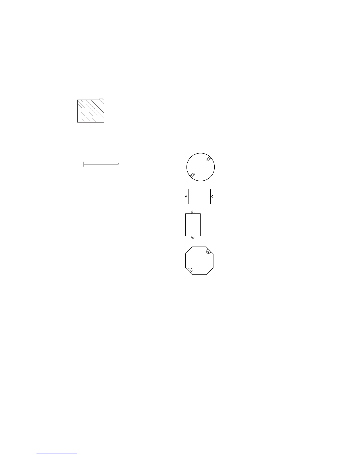
Fits All Junction Box Configurations
Circular
Horizontal rectangular
Vertical rectangular
Octagon

-5-
598-1118-04
Installation
If you want to use the Manual Override feature you will need to install the fixture on a circuit controlled
by a switch.
❒Loosen the thumbscrews holding the sensor
head and lampheads.
❒Adjust the various parts so that the fixture
looks similar to this illustration.
❒Finger tighten the thumbscrews at this time.
Wall Mount Eave Mount
❒Loosen the thumbscrews holding the sensor
head and lampheads.
❒Adjust the various parts so that the fixture
looks similar to this illustration.
❒Finger tighten the thumbscrews at this time.
CAUTION: BEFORE STARTING THE INSTALLATION, TURN THE POWER OFF AT THE
CIRCUIT BREAKER.

-6-
598-1118-04
CAUTION: If you have not already turned the
power off at the breaker or fuse, do so now.
Connect the junction box wires to the fixture wires.
Twist together and secure with wire connectors.
CAUTION: If you are not controlling additional
fixtures from your JourneyMan®fixture, DO NOT
connect the RED wire.
Standard Wiring
Black to
Black
White to
White
Mounting
Bracket
Green ground
wire to
junction box
ground wire
RED, not
used in most
applications
Gasket
Mount Fixture with Crossbar
Mounting Bracket
❒Turn power off at the fuse or circuit breaker.
❒Remove the existing light fixture (if appli-
cable).
❒Install the mounting bracket as shown using
two screws supplied in hardware pack that fit
your junction box:
Rectangular Junction Box - Use two #6-32
x 3/4" screws.
Circular or Octagonal Junction Box - Use
two #8-32 x 3/8" screws.
Watertight Junction Box - Use two #10-24
x 1/2" screws.
❒The plastic hanger can be used to hold the fix-
ture while wiring. The small end of the plastic
hanger can be threaded through the hole in the
center of the cover plate. The small end then
goes into one of the slots on the mounting
bracket.
❒Route the Light Control’s wires through the
large gasket holes.
Junction Box

-7-
598-1118-04
Controlling Non-Motion Sensing
Fixtures
❒When wiring to additional standard fixture
only: Strip the motion sensor's red wire and
connect to the standard light's black wire.
Connect all white wires together. Total fixture
ratings must not exceed 1000 Watts (8.3 A).
NOTE: All wiring between fixtures should be run
in accordance with the National Electrical
Code through conduit or another acceptable
means. Contact a qualified electrician if
there is any question as to the suitability of
the system.
❒This fixture is provided with a sensor rated
for 1000 Watts. Since the fixture is only rated
300 Watts, 700 Watts of additional load may
be controlled by this sensor.
❒When determining what a fixture is rated for,
do not simply look at the rating on the lamp in
the fixture. Look at the marking which speci-
fies the maximum lamp wattage for which the
fixture is suitable.
❒Once you have selected the fixtures to be con-
nected and determined their maximum ratings,
add these ratings up. For instance, if you have
3 fixtures rated 100 Watts, 150 Watts, and 75
Watts respectively, you have a total load of 325
Watts.
(Standard)
RED from
JourneyMan®to
BLACK from
Fixture
BLACK from
Switch to
BLACK from
JourneyMan®
Wiring to a Motion Light & Standard Fixture
WHITE from Line
to WHITE from
JourneyMan®
WHITE from Line
to WHITE from
Fixture

-8-
598-1118-04
Finish Mounting
❒Align the JourneyMan®cover plate, gasket,
and the mounting bracket hole. Secure with
M5 x 0.8 x 40 mm mounting screw supplied.
❒Push the rubber plug firmly into place.
❒If not installed on a weatherproof box, caulk
between the cover plate and mounting sur-
face with silicone weather sealant.
❒Adjust the lamp holders by loosening the lock
nuts but do not rotate the lamp holders more
than 180°from the factory setting. When
screwing in the floodlamps, do not overtighten.
To avoid water damage and
electrical shock, keep lamp
holders aimed below horizontal.
Specifications
Range . . . . . . . . . . . . . . Up to 100 feet (30.5 m) with
Range Boost On; up to 70
feet (21 m) with Range
Boost Off. (Varies with sur-
rounding temperature).
Sensing Angle . . . . . . . . Up to 270°
Fixture Load . . . . . . . . . Up to 300 Watts Maximum
Incandescent [Up to 150
Watts maximum each lamp
holder.]
Sensor Load Capacity . . Up to 1000 Watts (8.3 amps),
Incandescent
Power Requirements . . . 120 VAC, 60 Hz
Operating Modes . . . . . . TEST,AUTO,andMANUAL
OVERRIDE
Time Delay . . . . . . . . . . 1, 5, 20 minutes
Sensitivity . . . . . . . . . . . Adjustable
Rubber Plug DESA Specialty Products™ reserves the right to
discontinue products and to change specifications
at any time without incurring any obligation to in-
corporate new features in products previously sold.

-9-
598-1118-04
Test and Adjustment
NOTES: When first turned on wait about 1 1/2
minutes for the circuitry to calibrate.
Testing with Range Boost on during day-
light may result in abnormal operation.
Sensor Bottom
Do not aim the sensor at:
•Objects that change temperature rapidly, such
as heating vents and air conditioners, to help
avoid false triggering.
•Where pets or traffic may trigger the control.
•Nearby large, light-colored objects reflect-
ing light may trigger the shut-off feature. Do
not point other lights at the sensor.
❒Turn on the circuit breaker and light switch.
❒Open the control access cover (on bottom
of unit) by pulling down on the tab of the
rubber cover.
❒Turn the sensitivity control to the center of its
adjustment, RANGE BOOST to OFF and the
ON-TIME to TEST position.
MIN. MAX.
SENSITIVITY
Range Boost
OFF ON
2
0
TEST 1 5
ON TIME

-10-
598-1118-04
Adjustments Continued . . .
Aim Sensor Down
for Short Coverage
❒Loosen the thumbscrews, estimate the direction to aim the sensor and tighten
the thumbscrews just enough to hold the sensor in place.
❒Walk through the coverage area noting where you are when the lights turn
on. Loosen the thumbscrews and readjust the sensor as necessary. Tighten
the thumbscrews (finger tight) when you are satisfied with the coverage di-
rection. Keep the sensor at least 1 inch (25 mm) from lamps and keep the
controls on the bottom.
❒Adjust SENSITIVITY as needed to increase or decrease the range. Too much
sensitivity may cause false triggering.
❒Set the amount of TIME (1, 5, or 20 minutes) you want the lights to stay on
after motion is detected at night.
❒If you need to detect objects more than 70 feet (21 m) away, turn Range
Boost on. For maximum range, the sensor must be aiming straight out.
❒Replace the rubber cover to protect controls. Aim Sensor Out for
Long Coverage
Expected Coverage
The sensor is less sensitive to motion directly
towards it, most sensitive to motion across its
field of view.
When mounted 8 feet (2.4 m) from the ground, you
may expect the range shown below. If mounted much
higher the sensor may miss objects near the ground.
If mounted much lower the sensor range may be
reduced.
Sensor
Least Sensitive Most Sensitive
Motion Motion
Maximum Range
(Sensor aiming straight out)
8 ft.
(2.4 m)
70 ft. (21 m) 100 ft. (30,5 m)
(With Boost (With Boost On
Off and and Maximum
Maximum Sensitivity)
Sensitivity)

-11-
598-1118-04
If the wide angle (270°) coverage is too wide for
your application, you may need to install the lens
shield to reduce the coverage angle.
❒Decide which side of the lens you want to cover.
❒Curve the shield as shown. Slide the shield
down, under the two metal ribs of the case.
Make sure the shield slides all the way down
so the entire shield will lay directly against
the lens.
❒Slip the small protrusion behind the vertical
metal rib to hold the top of the shield in place.
Maximum
Coverage Angle
270°Approx. area
blocked by the
lens shield (if
used)
Slip behind
vertical rib Lens shield
Metal ribs
If the sensor is not kept level you may experi-
ence an apparent decrease in range because
objects may pass under the detection zone with-
out being detected.

-12-
598-1118-04
Operation
RANGE BOOST
Turn Range Boost on for addi-
tional coverage only if needed.
Off On
Range Boost
TEST 1 5 20
ON TIME
TEST
AUTO
ON TIME
TEST 1 5 20
* resets to Auto Mode at dawn.
Mode: On-Time: Works: Day Night
Test 5 Sec x x
Auto 1, 5, or 20 min. x
Manual Until Dawn* x
MANUAL MODE
... back on.
1 Second OFF
then
...
Move ON-TIME Switch
to 1, 5, or 20 minutes
Flip light switch
off for one second
then back on*
*If you get confused while switching modes,
turn the power off for one minute, then back
on. After the calibration time, the control will
be in the AUTO mode.
MANUAL MODE
AUTO
TEST
Put the ON-TIME switch on the
sensor bottom in TEST and the
Range Boost switch to Off.
Put the ON-TIME switch in the
1, 5, or 20 minute position.
Manual Mode only works at
night because daylight returns
the sensor to AUTO.
Flip the light switch off for one
second then back on to toggle
betweenAUTO and MANUAL
MODE.
Manual Mode works with the
ON-TIME switch in the 1, 5,
or 20 minute position.

-13-
598-1118-04
SYMPTOM
Lights will
not come
on.
Lights come
on in
daylight.
Lights come
on for no
apparent
reason.
SYMPTOM
Lights stay
on continu-
ously.
Lights flash
on and off.
POSSIBLE CAUSE
1. A lamp is positioned too close to
the sensor or pointed at objects
that causes the sensor to trigger.
(Aim the lamp away from the sen-
sor or objects).
2. Control is pointed at a heat source
likeanairvent,dryervent,orbrightly-
paintedheat-reflectivesurface.
(Re-
aim sensor. Turn Boost off).
1. Heat or light from the lamps may be
turning the Light Control on and off.
(Aim lamps away from the sensor.
Turn Boost off)
.
2. Reflected heat from other objects
are triggering the sensor.
(Re-aim
sensor. Turn Boost off)
.
3. Control is warming up.
(Flashing is
normalundertheseconditions.Wait
1 minute for sensor to warm up)
.
4. ControlisinTest.
(Setcontrol switch
to an ON-TIME position)
.
POSSIBLE CAUSE
1. Light switch is turned off.
2. Flood light is loose or burned out.
3. Fuse is blown or circuit breaker is
turned off.
4. Daylight turnoff is in effect.
(Re-
check after dark)
.
5. Incorrect circuit wiring, if this is a
new installation.
6. Re-aim the sensor to cover de-
sired area.
1. Control may be installed in a rela-
tively dark location.
2. Control is in Test.
(Set control
switch to an ON-TIME position)
.
1. Controlmaybesensingsmallani-
mals or automobile traffic.
(Re-
aim sensor or use lens shield)
.
2. Sensitivity is set too high.
(Reduce
sensitivity. Turn Range Boost off)
.
Troubleshooting Guide
Technical Service
Please call 1-800-858-8501 for assistance before returning product to store.
If you experience a problem, follow this guide. You may also want to visit our Web site at: www.desatech.com. If the
problem persists, call* for assistance at 1-800-858-8501, 7:30 AM to 4:30 PM CST (M-F). You may also write* to:
DESA Specialty Products™
P.O. Box 90004
Bowling Green, KY 42102-9004
ATTN: Technical Service Specialty Products
* If contacting Technical Service, please have the following information available: Model Number, Date of Purchase,
and Place of Purchase. No Service Parts Available for this Product

-14-
598-1118-04
JourneyMan®Lifetime Warranty
This is a “Limited Warranty” which gives you specific legal rights. You may also have other rights
which vary from state to state or province to province.
For as long as you (the original purchaser) own this JourneyMan®product, any malfunction caused
by factory defective parts or workmanship will be corrected at no charge to you. To obtain a refund
or a replacement, call 1-800-858-8501 for instructions.
Not Covered - Repair service, adjustment and calibration due to misuse, abuse or negligence,
light bulbs, batteries, and other expendable items are not covered by this warranty. Unauthorized
service or modification of the product or of any furnished component will void this warranty in its
entirety. This warranty does not include reimbursement for inconvenience, installation, setup time,
loss of use, unauthorized service, or return shipping charges.
This warranty covers only JourneyMan®products and is not extended to other equipment and
components that a customer uses in conjunction with our products.
THIS WARRANTY IS EXPRESSLY IN LIEU OF ALL OTHER WARRANTIES, EXPRESS OR IM-
PLIED, INCLUDINGANY WARRANTY, REPRESENTATION OR CONDITION OF MERCHANTABIL-
ITY OR THAT THE PRODUCTS ARE FIT FOR ANY PARTICULAR PURPOSE OR USE, AND SPE-
CIFICALLY IN LIEU OFALL SPECIAL, INDIRECT, INCIDENTAL, OR CONSEQUENTIAL DAMAGES.
REPAIR OR REPLACEMENT SHALL BE THE SOLE REMEDY OF THE CUSTOMER AND THERE
SHALL BE NO LIABILITY ON THE PART OF DESA FOR ANY SPECIAL, INDIRECT, INCIDEN-
TAL, OR CONSEQUENTIAL DAMAGES, INCLUDING BUT NOT LIMITED TO ANY LOSS OF
BUSINESS OR PROFITS, WHETHER OR NOT FORESEEABLE. Some states or provinces do
not allow the exclusion or limitation of incidental or consequential damages, so the above limitation
or exclusion may not apply to you. Proof of purchase is required for warranty claims.

-15-
598-1118-04
CONTROL DE LUZ YDETECTOR DE
MOVIMIENTO TODO HECHO DE METAL
Modelo HD-9250
© 2004 DESA Specialty Products™ 598-1118-04 S

-16-
598-1118-04
Indice
Introducción ............................................................................................... 17
Contenidos del Paquete ........................................................................ 18
Instalación ...................................................................................................19
Montaje en pared .................................................................................. 19
Montaje en alero ....................................................................................19
Soporte de montaje de la barra de cruce ........................................... 20
Cableado Estándar .................................................................................20
Control de los aparatos que no detectan movimiento .......................21
Fin del Montaje...................................................................................... 22
Especificaciones ..................................................................................... 22
Prueba y Ajuste .......................................................................................... 23
Cobertura Esperada .............................................................................. 24
Funcionamiento ..........................................................................................26
Guia de Investigacion de Averias ..............................................................27
Garantía de por Vida del JourneyMan®................................................... 28

-17-
598-1118-04
Introducción
Querido consumidor:
Deseamos agradecerle por haber comprado este producto JourneyMan®. Quienes trabajamos
para la Compañía DESA Specialty Products™ creemos que ha comprado el detector de movimiento
más durable que existe actualmente. Este producto JourneyMan® le ofrecerá un funcionamiento de por
vida. Tenemos tanta confianza en la durabilidad de este producto que lo respaldamos con una garantía
de por vida.
Características Mejoradas de Rendimiento
☞Los dientes fuertes de sujeción y el tornillos de mano ofrecen un ajuste completo de las tres
dimensiones de la cabeza del detector.
☞Los ocho empaques de caucho de silicona sellan los componentes y controles internos protegiéndolos
contra las condiciones ambientales severas.
☞Tornillos de acero inoxidable para evitar el enmohecimiento y la corrosión.
☞Protección incorporada de 1,25 mega vatios contra sobrecargas momentáneas.
☞El diseñoA.S.I.C. (Circuito Integrado deAplicación Específica) permite un rendimiento más confiable.
☞Opción de aumento de alcance para ampliar el alcance a aquellas áreas que son difíciles de cubrir.
☞Cobertura de ángulo extremadamente grande (hasta 270˚).
☞Fácil control de otras luces con su aparato JourneyMan® (hasta una carga total de 1000 vatios).
☞El área ampliada de la placa translúcida recibe más luz infrarroja mejorando así su sensibilidad
de detección.
☞La tecnología de cómputo de impulsos reduce una falsa detección, causada por el viento y la lluvia,
para obtener una confiabilidad profesional.
☞La fotecélula automática desactiva la unidad durante el día para ahorrar energía.
☞Restauración después de que se cortó la corriente. Apaga automáticamente las luces si se prenden
por interrupción de corriente o por una tormenta eléctrica.
☞Temporizador de luz seleccionable para fijar el tiempo que la luz se quede prendida después de
detectar movimiento.
☞El control de la sensibilidad permite el ajuste del alcance de cobertura.
☞Sobrecontrol manual para prender/apagar las luces, a su conveniencia, con el interruptor de pared ya
existente dentro de casa.

-18-
598-1118-04
Contenidos del Paquete
•Aparato de luz y detector de movimiento
•Protección de la placa translúcida
• Manual
•Paquete de ferretería
1empaquetadura
1gancho
1Soporte de montaje de la barra de cruce
4conectores de cable
2tornillos #6-32 x 3/4 pulgada.
(para cajas pequeñas rectangulares)
2tornillos #8-32 x 3/8 pulgada.
(para cajas circulares u octagonales)
2tornillos #10-24 x 1/2 pulgada.
(para cajas impermeables al agua)
1tornillos M5 x 0.8 x 40 mm.
(desde el aparato al soporte de montaje)
1Enchufe de caucho
Artículos adicionales que se
necesitan
•Destornillador Phillips
•Escalera
•2reflectores, 150 vatios máximo por lámpara
Queda bien con todas las
configuraciones de cajas de empalmes
Circular
Rectangular horizontal
Rectangular vertical
Octagonal

-19-
598-1118-04
Instalación
Si usted desea usar el sobrecontrol manual usted deberá instalar el aparato en un circuito controlado por
un interruptor.
❒Afloje los tornillos de mano que sostienen el
cabezal del detector y los cabezales de lámpara.
❒Ajuste las diferentes partes para que el
aparato se vea similar a esta ilustración.
❒Ahora ajuste los tornillos de mano sólo con
los dedos.
Montaje en pared Montaje en alero
❒Afloje los tornillos de mano que sostienen el
cabezal del detector y los cabezales de lámpara.
❒Ajuste las diferentes partes para que el aparato
se vea similar a esta ilustración.
❒Ahora ajuste los tornillos de mano sólo con
los dedos.
CUIDADO: ANTES DE COMENZAR LA INSTALACION , APAGUE LA CORRIENTE EN EL
CORTACIRCUITOS.

-20-
598-1118-04
CUIDADO: Si todavía no ha desconectado la
alimentación en el cortacircuito o fusible,
hágalo ahora.
Conecte los cables de la caja de empalmes a los
cables del aparato. Tuérzalos juntos y asegúrelos
con conectores de cable.
CUIDADO: Si no controlará aparatos adicionales
con su JourneyMan®, NO conecte el cable ROJO.
Cableado Estándar
Negro a
negro
Blanco a
blanco
Caja de
empalmes
ROJO, no usado en la
mayoría de las aplicaciones
Cable verde de a
tierra al cable de
a tierra de la caja
de empalme.
Empaquetadura
Instale el aparato con el soporte de
montaje de la barra de cruce
❒Apague la energía en el fusible o
cortacircuitos.
❒Quite el aparato de luz existente. (si es
aplicable).
❒Instale el soporte de montaje como se
demuestra usando los dos tornillos provistos
en su paquete de ferreterÌa y que es apropiado
para su caja de empalme:
Caja de Empalme Rectangular - Use dos tor-
nillos #6-32 x 3/4 pulgada.
Caja de Empalme Circular o Rectangular -
Use dos tornillos #8-32 x 3/8 pulgada.
Caja de Empalme impermeable - Use dos
tornillos #10-24 x 1/2 pulgada.
❒Se puede usar el colgador plástico para
sostener el aparato mientras se instala el
cableado. El extremo pequeño del colgador se
puede pasar por el agujero en el centro de la
placa cubertora. El extremo pequeño va luego
dentro de las ranuras de la lámina de montaje.
❒Pase todos los cables del aparato por los
agujeros grandes del empaque, como se
muestra.
Table of contents
Languages:
Other Desa Controllers manuals